Claas Torion 1177 (K55) Wheel Loaders Operator Manual EN
$50.00
- Model: Torion 1177 (K55) Wheel Loaders
- Type Of Manual: Operator Manual
- Language: EN
- Format: PDF(s)
- Size: 77.2 MB
File List:
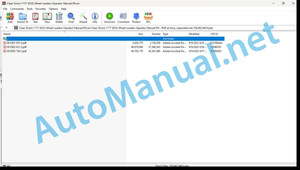
00 0301 051 0.pdf
00 0302 412 3.pdf
00 0303 738 2.pdf
00 0301 051 0.pdf:
PROFI CAM 3
Table of contents
1 Introduction
1.1 Notes on the manual
1.1.1 Validity of manual
1.1.2 Information about this Operator’s Manual
1.1.3 Symbols and notes
1.1.4 Optional equipment
1.1.5 Qualified specialist workshop
1.1.6 Maintenance information
1.1.7 Warranty notes
1.1.8 Spare parts and technical questions
1.2 Intended use
1.2.1 Intended use
1.2.2 Reasonably foreseeable misuse
2 Safety
2.1 Identifying warnings
2.1.1 Hazard signs
2.1.2 Signal word
2.2 Safety rules
2.2.1 Meaning of Operator’s Manual
2.2.2 Observing safety decals and warnings
2.2.3 Optional equipment and spare parts
3 Product description
3.1 Overview and method of operation
3.1.1 How the PROFI CAM works
3.2 Identification plates and identification number
3.2.1 Position of identification plates
3.2.2 Explanation of PROFI CAM identification plate
3.3 Information on the product
3.3.1 CE marking
4 Operating and control elements
4.1 Camera system
4.1.1 Camera system monitor
4.2 Menu structure
4.2.1 Main menu
4.2.2
4.2.3
4.2.4
4.2.5
4.2.6
5 Technical specifications
5.1 PROFI CAM
5.1.1 Monitor
5.1.2 Camera
5.1.3 Switch box
5.1.4 Degree of protection against foreign bodies and water
6 Preparing the product
6.1 Shutting down and securing the machine
6.1.1 Switching off and securing the machine
6.2 Prior to operation
6.2.1 Carry out prior to operation
6.2.2 Installing the sun protection
6.2.3 Aligning the camera
6.2.4 Connecting the camera electrics
7 Operation
7.1 Monitor
7.1.1 Switching on the monitor
7.1.2 Calling up the menu
7.1.3 Setting a menu item
7.1.4 Setting the image orientation
7.1.5 Setting automatic screen darkening
7.1.6 Image mirroring
7.1.7 Setting the trigger view
7.1.8 Setting the follow-up time for trigger view
7.1.9 Setting the display mode
7.1.10 Activating/deactivating a display mode
8 Faults and remedies
8.1 Electrical and electronic system
8.1.1 Overview of problems on PROFI CAM camera system
8.1.2 Replacing the switch box fuse
9 Maintenance
9.1 Maintenance intervals
9.1.1 Every 10 operating hours or daily
9.2 Camera system
9.2.1 Checking the camera system for dirt
9.2.2 Cleaning the camera
9.2.3 Cleaning the switch box
9.2.4 Cleaning the monitor
10 Placing out of operation and disposal
10.1 General Information
10.1.1 Putting out of operation and disposal
11 Technical terms and abbreviations
11.1 Abbreviations
11.1.1 Units
11.1.2 Abbreviations
11.1.3 Technical terms
00 0302 412 3.pdf:
TORION 1511TORION 1410TORION 1177
Table of contents
1 Introduction
1.1 General information
1.1.1 Validity of manual
1.1.2 Information about this Operator’s Manual
1.1.3 Symbols and notes
1.1.4 Optional equipment
1.1.5 Qualified specialist workshop
1.1.6 Maintenance notes
1.1.7 Notes on warranty
1.1.8 Spare parts and technical questions
1.2 Intended use
1.2.1 Intended use
1.2.2 Reasonably foreseeable misuse
2 Safety
2.1 Identifying warnings
2.1.1 Hazard signs
2.1.2 Signal word
2.2 Safety rules
2.2.1 Importance of Operator’s Manual
2.2.2 Observe the safety decals and warnings
2.2.3 Requirements for all persons working with the machine
2.2.4 Children in danger
2.2.5 Hazard areas
2.2.6 Persons riding on the machine
2.2.7 Hitching of machine to a trailer
2.2.8 Structural changes
2.2.9 Optional equipment and spare parts
2.2.10 Roll-over protective structure and falling object protective structure
2.2.11 Control of the machine while it is running
2.2.12 Operation only following proper putting into operation
2.2.13 Technical condition
2.2.14 Danger from damage to the machine
2.2.15 Respecting technical limit values
2.2.16 Keeping the safety devices functional
2.2.17 Personal protective equipment
2.2.18 Wearing suitable clothing
2.2.19 Removing dirt and loose objects
2.2.20 Field of view and viewing aids
2.2.21 Preparing the machine for road travel
2.2.22 Hazards when driving on the road and on the field
2.2.23 Parking the machine safely
2.2.24 Unsuitable operating utilities
2.2.25 Safe handling of operating and auxiliary utilities
2.2.26 Fuel is harmful to your health
2.2.27 Refrigerant is harmful to your health
2.2.28 Environmental protection and disposal
2.2.29 Keep the cab free of chemicals
2.2.30 Fire hazard
2.2.31 Potentially fatal electric shock from electric overhead lines
2.2.32 Behaviour in case of voltage flashover from overhead lines and of lightning strikes
2.2.33 Electrocution by electrical system
2.2.34 Oscillations may damage your health
2.2.35 Pressurised fluids
2.2.36 Toxic exhaust gas
2.2.37 Auxiliary heater
2.2.38 Hot surfaces
2.2.39 Accessing and leaving the machine safely
2.2.40 Working on machine only after shutting it down
2.2.41 Maintenance operations and repair work
2.2.42 Lifted loads
2.2.43 Danger from welding work
2.2.44 Checking and charging the battery
2.3 Safety marking
2.3.1 Layout of safety decals
2.3.2 Warning signs on the machine
Safety decal
Safety decal
Safety decal
Safety decal
Safety decal
Safety decal
Safety decal
Safety decal
Safety decal
3 Machine description
3.1 Overview and method of operation
3.1.1 Overview of the wheel loader
3.1.2 Overview of the work lighting and headlights
3.2 Optional equipment
3.2.1 Coolant pre-heating*
3.2.2 Auxiliary heater with engine pre-heater
3.2.3 Reversible fan drive*
3.2.4 Weighing system
3.2.5 Tool carrier with multi-coupling
3.2.6 Crane arm
3.2.7 Reversing obstacle detector
3.3 Identification plates and identification numbers
3.3.1 Position of the identification plate
3.3.2 Details provided on the identification plate
3.3.3 Identification plate for the auxiliary heater*
3.4 Information on the machine
3.4.1 Position of decals
3.4.2 Decals
Lubrication chart (1)
Fire extinguisher (2)
Sound power level (3)
Working hydraulics (4)
Working hydraulics (4)
Windscreen washer liquid (5)
Cooling system (6)
Sling point, lifting point (8)
Ground speed (9)
Lashing point (10)
Oil level (11)
Load-bearing capacity table for pallet fork operation* (13)
Emergency exit (14)
Check the fastening of wheels (15)
Dynamic steering (16)
Joystick steering (17)
Diesel fuel (18)
Urea solution (19)
Keep off! (20)
Refrigerant* (21)
Battery isolating switch (22)
4 Operating and display elements
4.1 Cab and operator’s platform
4.1.1 Operator’s platform
4.1.2 Control unit
4.1.3 Switch
4.1.4 Multifunction handle
4.1.5 Multi-lever control*
4.1.6 Ignition lock
4.1.7 Steering column switch
4.2 On-board information system
4.2.1 Warnings and fault messages
4.2.2 Display
4.2.3 Overview of symbols
4.2.4 Main menu
4.2.5 Start page
4.2.6
4.2.7
4.2.8
4.2.9
4.2.10
4.2.11
4.2.12
Operating display
Status messages
4.2.13 Display of the reversing obstacle detector*
5 Technical specifications
5.1 TORION
5.1.1 Dimensions with bucket
5.1.2 Dimensions with bucket
5.1.3 Dimensions with light material bucket
5.1.4 Dimensions with high dump bucket
5.1.5 Dimensions with pallet fork
5.1.6 Dimensions with timber grabber
5.1.7 Dimensions with bucket
5.1.8 Dimensions with bucket
5.1.9 Dimensions with light material bucket
5.1.10 Dimensions with high dump bucket
5.1.11 Dimensions with pallet fork
5.1.12 Dimensions with timber grabber
5.1.13 Dimensions with bucket
5.1.14 Dimensions with bucket
5.1.15 Dimensions with light material bucket
5.1.16 Dimensions with high dump bucket
5.1.17 Dimensions with pallet fork
5.1.18 Dimensions with timber grabber
5.1.19 Vibrations
Hand/arm vibrations
Whole-body vibrations
5.1.20 Sound pressure level and sound power level
5.1.21 Temperature of use
5.1.22 4045HLC09 diesel engine
CO2 emissons
5.1.23 4045HLC09 diesel engine
CO2 emissons
5.1.24 4045HLC07 diesel engine
CO2 emissons
5.1.25 Refuelling pump*
5.1.26 Chassis
Ground drive
Ground speed
5.1.27 Axles
Front axle
Rear axle
5.1.28 Tyres and tyre pressure
5.1.29 Tyres and tyre pressure
5.1.30 Tyres and tyre pressure
5.1.31 Snow chains* or guard chains*
5.1.32 Foam-filled tyres*
5.1.33 Brake
5.1.34 Steering
5.1.35 Lift arms
Working cycle time with permissible load capacity and Z kinematics
Working cycle time with permissible load capacity and P kinematics
5.1.36 Lift arms
Working cycle time with permissible load capacity and Z kinematics
Working cycle time with permissible load capacity and P kinematics
5.1.37 Load-bearing capacity table for telescoping crane arm
5.1.38 Tow hitch
5.1.39 Hydraulic system
5.1.40 Electric system
5.1.41 Cab
Driver’s seat
Heating, ventilation
Air conditioning system*
5.1.42 Ballast
5.1.43 Reversing obstacle detector*
5.2 Operating utilities
5.2.1 Lubricants
5.2.2 Hydraulic oil
5.2.3 Coolant
5.2.4 Fuels
5.2.5 Refrigerant
6 Machine preparation
6.1 Switching off and securing the machine
6.1.1 Switching off and securing the machine
6.1.2 Lowering the working attachment to the ground
6.1.3 Switching the battery isolating switch on and off
6.1.4 Securing the machine against rolling away
Leaving the machine when the diesel engine is switched off
Leaving the machine when the diesel engine is switched on
6.2 Accessing workplaces and maintenance spaces
6.2.1 Accessing the workplace in the cab
Standard door
Accessing the cab
Leaving the cab
Comfort safety door
Accessing the cab
Leaving the cab
6.3 Diesel engine
6.3.1 Observing the fuel specification
6.3.2 Observe urea specification
Use of the urea solution
Purity and standard of urea solution
Storage of urea solution in tanks and containers
Properties of urea solution at high and low outside temperatures
6.3.3 Selecting a permissible fuel and urea solution
6.3.4 Refuelling the machine
Refuelling fuel
Topping up urea solution
6.3.5 Refuelling the machine with the refuelling pump*
6.4 Lift arms and working attachment
6.4.1 Removing the transport safety retainer for the lift arms
6.4.2 Removing the working attachment
6.4.3 Relieving the hydraulic pressures of the lift arms
Operation with the multifunction handle
Operation with the mini joystick
Operation with the multi-lever control unit
6.4.4 Disconnecting the hydraulic lines
6.4.5 Unlocking and disconnecting the working attachment
6.4.6 Unlocking and disconnecting the working attachment with multi-coupling*
6.4.7 Installing the working attachment
6.4.8 Hitching and locking the working equipment
6.4.9 Hitching and locking the implement with multi-coupling*
6.4.10 Connecting the hydraulic lines
Connecting the hydraulic lines
6.4.11 Checking the working attachment lock
Visual inspection
Mechanical check
6.4.12 Checking the lock of the working attachment with multi-coupling*
Visual inspection
Mechanical check
6.4.13 Calibrating the working attachment
6.5 Loading the machine
6.5.1 Preparing the machine for loading
6.5.2 Loading the machine
6.5.3 Driving the machine on a loading space
6.5.4 Driving the machine from a loading space
6.5.5 Lashing down the machine
6.5.6 Articulation lock
Engaging the articulation lock
Releasing the articulation lock
6.6 Electric and electronic system
6.6.1 Setting the time and date
6.6.2 Set the system of units
6.6.3 Setting the system language
6.6.4 Resetting the daily operating hours
6.6.5 Setting the display brightness and volume
7 Operation
7.1 Driving and transportation
7.1.1 Preparing for driving operation
7.1.2 Preparing road travel
7.1.3 Carry out a function check
7.1.4 Switching the road travel switch
7.1.5 Driving
Starting off the machine
7.1.6 Driving downhill with overspeed protection
7.1.7 Transporting the load on a slope
7.1.8 Driving on sloping ground
7.1.9 Picking up material
7.1.10 Transporting and transferring material
7.1.11 Emptying the working attachment
7.1.12 Handling materials with high dump buckets
7.1.13 Loading with a clamp bucket
7.1.14 Levelling
Forward levelling
Backwards levelling
7.1.15 Removing material
Removing material from the slope
Removing material from the wall
7.1.16 Loading a transport vehicle
Transport routes
Loading process
7.1.17 Working near electric overhead lines
7.1.18 Loading large rocks
7.1.19 Reversing the machine
7.1.20 Excavating material
Excavating foundations
7.1.21 Towing the machine from the hazard area
Towing with the diesel engine running
After towing
Towing with the diesel engine switched off
After towing
7.1.22 Setting the ground drive to free circulation
7.1.23 Switching off the proportional solenoid on the travel motor
7.2 Diesel engine
7.2.1 Pre-heating the coolant in the diesel engine*
7.2.2 Operating the auxiliary heater*
Bringing the drive hydraulics and working hydraulics to operating temperature
7.2.3 Starting the diesel engine
Speed increase for improving the charging capacity
7.2.4 Switching off the diesel engine
7.2.5 Setting the automatic diesel engine shutdown*
7.2.6 Fuel consumption indicator
7.3 Chassis
7.3.1 Tachometer*
7.3.2 Selecting the travel direction switch
7.3.3 Selecting the direction of travel
7.3.4 Selecting travel ranges
7.3.5 Driving with speed limitation
7.3.6 Setting vibration dampening*
7.3.7 Switching vibration damping* on and off
7.4 Brake
7.4.1 Braking the machine
7.4.2 Applying and releasing the parking brake
7.4.3 Releasing the parking brake mechanically
7.5 Steering
7.5.1 Dynamic steering*
7.5.2 Joystick steering*
Activating joystick steering
Operating joystick steering
Deactivating joystick steering
7.5.3 Setting the reaction speed of joystick steering
7.5.4 Activating the emergency steering function
Automatic emergency steering
Activating the emergency steering function manually
7.6 Lift arms and working attachment
7.6.1 Blocking and releasing the working hydraulics
7.6.2 Moving the lift arms and working attachment
7.6.3 Moving the lift arms and the working attachment with the multi-lever control unit*
7.6.4 Activating and deactivating the float position
7.6.5 Setting the lifting height limitation
Activating lifting height limitation
Defining the work application
7.6.6 Setting the lowering depth limitation
Activating lowering depth limitation
Defining the work application
7.6.7 Setting end-of-stroke damping*
7.6.8 Setting automatic bucket return-to-dig
Automatic bucket return-to-dig via inductive sensor
Activating automatic bucket return-to-dig
Automatic bucket return-to-dig via angle sensor
Activating automatic bucket return-to-dig
Defining the work application
7.6.9 Operating a working attachment with its own hydraulic oil supply with the multi-lever control unit*
7.6.10 Setting the multi-lever control unit*
7.6.11 Calling up the setting for the working attachment
7.6.12 Change the control direction of the working attachment
7.6.13 Changing the speed of movement
7.6.14 Setting continuous operation*
7.6.15 Restoring the factory settings
7.6.16 Operating a working attachment with its own hydraulic oil supply with the mini joystick*
7.6.17 Operating the mini joystick
Controlling the hydraulic working attachment
7.6.18 Setting the mini joystick
7.6.19 Calling up the setting for the working attachment
7.6.20 Change the control direction of the working attachment
7.6.21 Changing the speed of movement
7.6.22 Setting continuous operation*
7.6.23 Restoring the factory settings
7.6.24 Setting the tilt speed
7.6.25 Operating the pallet fork*
Adjusting the fork arms on the fork carrier
Working with the pallet fork
7.6.26 Emergency operation of the lift arms
7.6.27 Activating the 3rd function* of automatic bucket return
7.6.28 Operating the crane arm*
Adjusting the crane arm
Working with the crane arm
7.7 Electric and electronic system
7.7.1 Engaging the parking position
7.7.2 Switching the lighting on and off
Switching the dipped beam on and off
Switching the main beam on and off
Switching the work lights on and off
Switching the warning beacon* on and off
7.7.3 Adjusting the illuminance of work lights*
7.7.4 Switching the reversing warning systems* on and off
7.7.5 Adjusting the rear camera
7.7.6 Electronic immobiliser*
Deactivating the electronic immobilizer
Teaching in the ignition key
Deleting an ignition key
Displaying the ignition key serial number
7.7.7 Driver identification*
Starting key: Deleting saved functions
7.7.8 Immobiliser with code entry*
7.8 Cab and operator’s platform
7.8.1 Adjusting the driver’s seat
Adjusting the mechanically suspended driver’s seat*
Adjusting the air-sprung driver’s seat with low-frequency suspension*
To set the operating mode
Adjusting the air-sprung driver’s seat with low-frequency suspension and seat climate control*
Adjusting the left and right armrest
7.8.2 Applying the seat belt
7.8.3 Adjusting the steering column
7.8.4 Adjusting the internal and external mirrors
7.8.5 Adjusting the heating and air conditioning system
Automatic mode*
Air conditioning mode*
Recirculated air mode
Defrost mode
Regulating the temperature
Adjusting the blower
Adjusting the air distribution
7.8.6 Switching the cab interior lighting on and off
7.8.7 Adjusting the sun visor
7.8.8 Opening and closing the cab window
7.8.9 Opening the emergency exit
7.8.10 Switching the rear window heating and exterior mirror heating on and off
7.8.11 Actuating the windscreen washer
7.9 Central lubrication system
7.9.1 Central lubrication system*
Lubrication procedure
Low grease reservoir level
Cycle error
7.10 Weighing system
7.10.1 Weighing position
7.10.2 Operating the weighing system
7.10.3 Keys and symbols
Operating display
Status messages
7.10.4 Acoustic signals
7.10.5 Calling up the weighing system
7.10.6 Weighing process
7.10.7 Set weighing system to zero
Selection of working attachment*
7.10.8 Weighing the bucket contents
7.10.9 Total weighing
7.10.10 Target weight weighing
Entering a target weight
Weighing process
7.10.11 Trailer weighing
7.10.12 Reweigh
7.10.13 Cancel
7.10.14 Displaying the start page during the weighing process
7.10.15 Bringing the working hydraulics up to operating temperature
7.10.16 Weighing system statistics
8 Faults and remedies
8.1 Overview
8.1.1 Overview of fault codes
8.1.2 Overview of warning symbols
Warning symbols for the SCR system
8.2 Diesel engine
8.2.1 Overview of diesel engine faults
8.3 Electric and electronic system
8.3.1 Assist-starting 24 V
Charging the batteries
8.3.2 Replacing fuses
Fuse board A4
Fuse board A4b
Fuses in the right ballast weight
8.3.3 Overview of weighing system faults
Acoustic signals
Error messages
8.3.4 Overview of reversing obstacle detector faults
8.3.5 Overview of faults on immobilizer
8.4 Central lubrication system
8.4.1 Overview of faults on the central lubrication system
9 Maintenance
9.1 Maintenance intervals
9.1.1 Maintenance
9.1.2 Every 10 operating hours or daily
9.1.3 Every 50 operating hours
9.1.4 After the first 500 operating hours
9.1.5 Every 500 operating hours
9.1.6 Every 1000 operating hours
9.1.7 Every 2 years
9.1.8 Every 2000 operating hours
9.1.9 Every 3000 operating hours
9.1.10 Every 4000 operating hours
9.1.11 Every 4500 operating hours
9.1.12 Every 6000 operating hours
9.1.13 Every 8000 operating hours
9.2 Lubrication plan
9.2.1 Grease points, grease every 10 working hours
9.2.2 Lubricate lubrication points every 50 working hours
9.2.3 Grease points, grease every 500 working hours
9.3 Preparing maintenance
9.3.1 Moving the machine to the maintenance position
Maintenance position I
Maintenance position II
9.3.2 Opening the service hatches
9.4 Diesel engine
9.4.1 Cleaning the diesel engine
9.4.2 Checking the diesel engine oil level
9.4.3 Draining condensed water from the fuel tank
9.4.4 Draining condensed water from the fuel sediment filter
9.4.5 Checking the coolant level
9.4.6 Reversing the fan
9.4.7 Cleaning the cooling system
9.4.8 Cleaning the air filter
9.4.9 Cleaning the air filter element
9.4.10 Replacing the air filter safety cartridge
9.4.11 Regenerating the diesel particulate filter
Setting regeneration mode
Starting regeneration automatically
Suppressing regeneration
Starting regeneration manually
9.5 Chassis
9.5.1 Checking the wheels, tyres and the tyre pressure
9.5.2 Checking the tyre pressure
9.5.3 Checking the tightening torque of wheel nuts
9.6 Brake
9.6.1 Checking the function and effect of the service brake
9.6.2 Checking the function and effect of the parking brake
9.7 Steering
9.7.1 Checking the steering system function
9.8 Lift arms and working attachment
9.8.1 Checking the function of the tool carrier
9.8.2 Replacing the teeth or undercut blade
Replacing the teeth
Changing the undercut blade
9.9 Hydraulic system
9.9.1 Checking the hydraulic oil level
Topping up hydraulic oil
9.9.2 Checking the hydraulic hoses
Marking of hydraulic hoses
9.10 Electric and electronic system
9.10.1 Checking the lights and horn
9.11 Cab and operator’s platform
9.11.1 Cleaning the cab
Cleaning inside the cab
Cleaning the front windscreen
9.11.2 Cleaning or replacing the cab air filter
9.11.3 Checking the condition and function of the seat belt
9.11.4 Topping up windscreen washer
9.11.5 Checking the function of the windscreen washer system
9.11.6 Cleaning and maintaining the cab seals
9.11.7 Checking the heater and air conditioning system
9.12 Central lubrication system
9.12.1 Filling the central lubrication system* lubricant reservoir
9.12.2 Checking the tightness and function of the central lubrication system*
9.13 Assembled parts/Machine housing
9.13.1 Checking the fire extinguishers
9.13.2 Checking the proper condition of the machine
9.13.3 Removing loose parts and pollution from the machine
9.13.4 Cleaning the machine
Prior to cleaning
Cleaning
After cleaning
9.13.5 Cleaning and maintaining the seals of the service hatches
9.13.6 Storing the machine
10 Putting out of operation and disposal
10.1 General information
10.1.1 Removal from service and disposal
11 EC declaration of conformity
11.1 TORION
11.1.1 EC declaration of conformity (sample)
00 0303 738 2.pdf:
TORION 1511TORION 1410TORION 1177
Table of contents
1 Introduction
1.1 General information
1.1.1 Validity of manual
1.1.2 Information about this Operator’s Manual
1.1.3 Symbols and notes
1.1.4 Optional equipment
1.1.5 Qualified specialist workshop
1.1.6 Maintenance notes
1.1.7 Notes on warranty
1.1.8 Spare parts and technical questions
1.2 Intended use
1.2.1 Intended use
1.2.2 Reasonably foreseeable misuse
2 Safety
2.1 Identifying warnings
2.1.1 Hazard signs
2.1.2 Signal word
2.2 Safety rules
2.2.1 Importance of Operator’s Manual
2.2.2 Observing safety decals and warnings
2.2.3 Requirements for all persons working with the machine
2.2.4 Children in danger
2.2.5 Hazard areas
2.2.6 Persons riding on the machine
2.2.7 Hitching of machine to a trailer
2.2.8 Structural alterations
2.2.9 Optional equipment and spare parts
2.2.10 Roll-over protective structure and falling object protective structure
2.2.11 Control of the machine while it is running
2.2.12 Operation only following proper putting into operation
2.2.13 Technical condition
2.2.14 Danger from damage to the machine
2.2.15 Respecting technical limit values
2.2.16 Keeping safety devices functional
2.2.17 Personal protective equipment
2.2.18 Wearing suitable clothing
2.2.19 Removing dirt and loose objects
2.2.20 Field of view and viewing aids
2.2.21 Preparing the machine for road travel
2.2.22 Hazards when driving on the road and on the field
2.2.23 Parking the machine safely
2.2.24 Unsuitable operating utilities
2.2.25 Safe handling of operating and auxiliary utilities
2.2.26 Fuel is harmful to your health
2.2.27 Refrigerant is harmful to your health
2.2.28 Environmental protection and disposal
2.2.29 Keeping the cab free of chemicals
2.2.30 Avoiding fires
2.2.31 Potentially fatal electric shock from electric overhead lines
2.2.32 Behaviour in case of voltage flashover from overhead lines and of lightning strikes
2.2.33 Electrocution by electrical system
2.2.34 Oscillations may damage your health
2.2.35 Pressurised fluids
2.2.36 Toxic exhaust gas
2.2.37 Auxiliary heater
2.2.38 Hot surfaces
2.2.39 Accessing and leaving the machine safely
2.2.40 Working on machine only after shutting it down
2.2.41 Maintenance operations and repair work
2.2.42 Lifted loads
2.2.43 Danger from welding work
2.2.44 Checking and charging the battery
2.3 Safety marking
2.3.1 Layout of safety decals
2.3.2 Warning signs on the machine
Safety decal
Safety decal
Safety decal
Safety decal
Safety decal
Safety decal
3 Machine description
3.1 Overview and method of operation
3.1.1 Overview of the wheel loader
3.1.2 Overview of the work lighting and headlights
3.2 Optional equipment
3.2.1 Coolant pre-heating*
3.2.2 Auxiliary heater* with engine pre-heater
3.2.3 Jump starting auxiliary unit*
3.2.4 Reversible fan drive*
3.2.5 Weighing system*
3.2.6 Tool carrier with multi-coupling
3.2.7 Crane arm*
3.2.8 Reversing obstacle detector*
3.3 Identification plates and identification numbers
3.3.1 Position of the identification plate
3.3.2 Details provided on the identification plate
3.3.3 Identification plate for the auxiliary heater*
3.4 Information on the machine
3.4.1 Position of decals
3.4.2 Decals
Lubrication chart (1)
Fire extinguisher (2)
Sound power level (3)
Working hydraulics (4)
Working hydraulics (4)
Windscreen washer liquid (5)
Cooling system (6)
Coolant (7)
Sling point, lifting point (8)
Ground speed (9)
Lashing point (10)
Oil level (11)
Hydraulic oil (12)
Load-bearing capacity table for pallet fork operation* (13)
Emergency exit (14)
Dynamic steering* (15)
Joystick steering* (16)
Safety belt (17)
Diesel fuel (18)
Urea solution (19)
Keep off! (20)
Refrigerant* (21)
Battery isolating switch (22)
4 Operating and display elements
4.1 Cab and operator’s platform
4.1.1 Operator’s platform
4.1.2 Control unit
4.1.3 Switch
4.1.4 Multifunction handle
4.1.5 Joystick steering*
4.1.6 Multi-lever control*
4.1.7 Ignition lock
4.1.8 Steering column switch
4.2 On-board information system
4.2.1 Display
4.2.2 Overview of symbols
4.2.3 Main menu
4.2.4
Daily operating hours counter
Fuel consumption and urea consumption
Current fuel consumption and urea consumption
Trip recorder*
Tyre pressure and tyre air temperature*
Visualisation of equipment position
4.2.5
Fault codes
Warning tone
4.2.6
4.2.7
4.2.8
John Deere Repair Technical Manual PDF
John Deere Repair Technical Manual PDF
John Deere DF Series 150 and 250 Transmissions (ANALOG) Component Technical Manual CTM147 05JUN98
John Deere Repair Technical Manual PDF
John Deere Diesel Engines PowerTech 4.5L and 6.8L – Motor Base Technical Manual 07MAY08 Portuguese
John Deere Repair Technical Manual PDF
John Deere Repair Technical Manual PDF
John Deere Repair Technical Manual PDF
John Deere Repair Technical Manual PDF
John Deere Parts Catalog PDF
John Deere Tractors 7500 Parts Catalog CPCQ26568 30 Jan 02 Portuguese
John Deere Repair Technical Manual PDF


