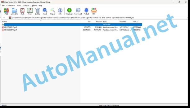
Claas Torion 2014 (K63) Wheel Loaders Operator Manual EN
$50.00
- Model: Torion 2014 (K63) Wheel Loaders
- Type Of Manual: Operator Manual
- Language: EN
- Format: PDF(s)
- Size: 42.3 MB
File List:
00 0301 051 0.pdf
00 0305 387 0.pdf
00 0301 051 0.pdf:
PROFI CAM 3
Table of contents
1 Introduction
1.1 Notes on the manual
1.1.1 Validity of manual
1.1.2 Information about this Operator’s Manual
1.1.3 Symbols and notes
1.1.4 Optional equipment
1.1.5 Qualified specialist workshop
1.1.6 Maintenance information
1.1.7 Warranty notes
1.1.8 Spare parts and technical questions
1.2 Intended use
1.2.1 Intended use
1.2.2 Reasonably foreseeable misuse
2 Safety
2.1 Identifying warnings
2.1.1 Hazard signs
2.1.2 Signal word
2.2 Safety rules
2.2.1 Meaning of Operator’s Manual
2.2.2 Observing safety decals and warnings
2.2.3 Optional equipment and spare parts
3 Product description
3.1 Overview and method of operation
3.1.1 How the PROFI CAM works
3.2 Identification plates and identification number
3.2.1 Position of identification plates
3.2.2 Explanation of PROFI CAM identification plate
3.3 Information on the product
3.3.1 CE marking
4 Operating and control elements
4.1 Camera system
4.1.1 Camera system monitor
4.2 Menu structure
4.2.1 Main menu
4.2.2
4.2.3
4.2.4
4.2.5
4.2.6
5 Technical specifications
5.1 PROFI CAM
5.1.1 Monitor
5.1.2 Camera
5.1.3 Switch box
5.1.4 Degree of protection against foreign bodies and water
6 Preparing the product
6.1 Shutting down and securing the machine
6.1.1 Switching off and securing the machine
6.2 Prior to operation
6.2.1 Carry out prior to operation
6.2.2 Installing the sun protection
6.2.3 Aligning the camera
6.2.4 Connecting the camera electrics
7 Operation
7.1 Monitor
7.1.1 Switching on the monitor
7.1.2 Calling up the menu
7.1.3 Setting a menu item
7.1.4 Setting the image orientation
7.1.5 Setting automatic screen darkening
7.1.6 Image mirroring
7.1.7 Setting the trigger view
7.1.8 Setting the follow-up time for trigger view
7.1.9 Setting the display mode
7.1.10 Activating/deactivating a display mode
8 Faults and remedies
8.1 Electrical and electronic system
8.1.1 Overview of problems on PROFI CAM camera system
8.1.2 Replacing the switch box fuse
9 Maintenance
9.1 Maintenance intervals
9.1.1 Every 10 operating hours or daily
9.2 Camera system
9.2.1 Checking the camera system for dirt
9.2.2 Cleaning the camera
9.2.3 Cleaning the switch box
9.2.4 Cleaning the monitor
10 Placing out of operation and disposal
10.1 General Information
10.1.1 Putting out of operation and disposal
11 Technical terms and abbreviations
11.1 Abbreviations
11.1.1 Units
11.1.2 Abbreviations
11.1.3 Technical terms
00 0305 387 0.pdf:
TORION 2014TORION 1913
Table of contents
1 Introduction
1.1 General information
1.1.1 Validity of manual
1.1.2 Information about this Operator’s Manual
1.1.3 Symbols and notes
1.1.4 Optional equipment
1.1.5 Qualified specialist workshop
1.1.6 Maintenance notes
1.1.7 Notes on warranty
1.1.8 Spare parts and technical questions
1.2 Intended use
1.2.1 Intended use
1.2.2 Reasonably foreseeable misuse
2 Safety
2.1 Identifying warnings
2.1.1 Hazard signs
2.1.2 Signal word
2.2 Safety rules
2.2.1 Importance of Operator’s Manual
2.2.2 Observing safety decals and warnings
2.2.3 Requirements for all persons working with the machine
2.2.4 Children in danger
2.2.5 Hazard areas
2.2.6 Persons riding on the machine
2.2.7 Hitching the machine to the working attachment
2.2.8 Hitching of machine to a trailer
2.2.9 Structural alterations
2.2.10 Optional equipment and spare parts
2.2.11 Roll-over protective structure and falling object protective structure
2.2.12 Control of the machine while it is running
2.2.13 Operation only following proper putting into operation
2.2.14 Technical condition
2.2.15 Danger from damage to the machine
2.2.16 Respecting technical limit values
2.2.17 Keeping safety devices functional
2.2.18 Personal protective equipment
2.2.19 Wearing suitable clothing
2.2.20 Removing dirt and loose objects
2.2.21 Field of view and viewing aids
2.2.22 Preparing the machine for road travel
2.2.23 Hazards when driving on the road and on the field
2.2.24 Parking the machine safely
2.2.25 Towing or salvaging the machine
2.2.26 Unsuitable operating utilities
2.2.27 Safe handling of operating and auxiliary utilities
2.2.28 Fuel is harmful to your health
2.2.29 Refrigerant is harmful to your health
2.2.30 Environmental protection and disposal
2.2.31 Keeping the cab free of chemicals
2.2.32 Avoiding fires
2.2.33 Potentially fatal electric shock from electric overhead lines
2.2.34 Behaviour in case of voltage flashover from overhead lines and of lightning strikes
2.2.35 Electrocution by electrical system
2.2.36 Oscillations may damage your health
2.2.37 Pressurised fluids
2.2.38 Toxic exhaust gas
2.2.39 Auxiliary heater
2.2.40 Hot surfaces
2.2.41 Accessing and leaving the machine safely
2.2.42 Working on machine only after shutting it down
2.2.43 Maintenance operations and repair work
2.2.44 Lifted loads
2.2.45 Danger from welding work
2.2.46 Checking and charging the battery
2.2.47 Auxiliary heater
2.3 Safety marking
2.3.1 Layout of safety decals
2.3.2 Warning signs on the machine
Safety decal
Safety decal
Safety decal
Safety decal
3 Machine description
3.1 Overview and method of operation
3.1.1 Overview of the wheel loader
3.1.2 Overview of the work lighting and headlights
3.2 Optional equipment
3.2.1 Coolant pre-heating*
3.2.2 Auxiliary heater* with engine pre-heater
3.2.3 Jump starting auxiliary unit*
3.2.4 Reversible fan drive*
3.2.5 Weighing system*
3.2.6 Tool carrier with multi-coupler*
3.2.7 Crane arm*
3.2.8 Reversing obstacle detector*
3.3 Identification plates and identification numbers
3.3.1 Position of the identification plate
3.3.2 Details provided on the identification plate
3.3.3 Identification plate for the auxiliary heater*
3.3.4 Identification plate of bucket with load hook*
3.4 Information on the machine
3.4.1 Position of decals
3.4.2 Decals
Windscreen washer liquid (1)
Lubrication chart (2)
Fire extinguisher (3)
Sound power level (4)
Working hydraulics (5)
Working hydraulics (5)
Cooling system (7)
Hydraulic oil level (8)
Coolant (9)
Refrigerant* (10)
Sling point, lifting point (11)
Lashing point (12)
Ground speed (13)
Hydraulic oil (14)
Emergency exit (15)
Load-bearing capacity table for pallet fork operation* (16)
Dynamic steering* (17)
Joystick steering* (18)
Safety belt (19)
Diesel fuel (20)
Urea solution (21)
4 Operating and display elements
4.1 Cab and operator’s platform
4.1.1 Operator’s platform
4.1.2 Control unit
4.1.3 Switches and keys
4.1.4 Multifunction handle
4.1.5 Joystick steering*
4.1.6 Multi-lever control*
4.1.7 Ignition lock
4.1.8 Steering column switch
4.2 On-board information system
4.2.1 Display
4.2.2 Overview of symbols
4.2.3 Main menu
4.2.4
Daily operating hours counter
Fuel consumption and urea consumption
Current fuel consumption and urea consumption
Trip recorder*
Tyre pressure and tyre air temperature*
Visualisation of equipment position
4.2.5
Fault codes
Warning tone
4.2.6
4.2.7
4.2.8


