Claas Torion 537 Sinus (K51) Wheel Loaders Repair Manual ES
$100.00
- Model: Torion 537 Sinus (K51) Wheel Loaders
- Type Of Manual: Repair Manual
- Language: ES
- Format: PDF(s)
- Size: 49.1 MB
File List:
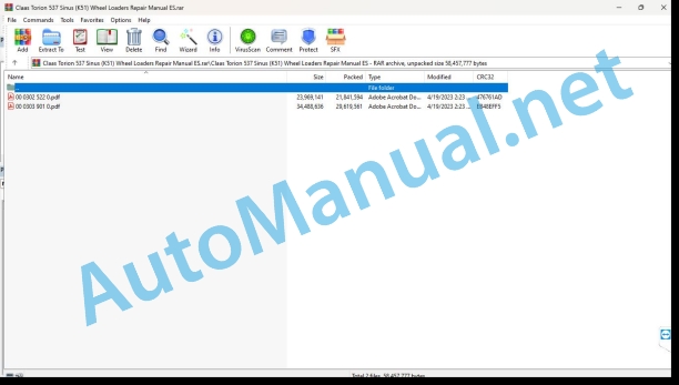
00 0302 522 0.pdf
00 0303 901 0.pdf
00 0302 522 0.pdf:
YANMAR 4TNV98CYANMAR 4TNV98CT
Introduction
General information
Manual validity
Using the manual
Texts and figures
Division with construction group structure
Search and find
Direction signs
Abbreviations
Technicalities
General repair instructions
Technical instructions
Indications for correct repair
Self-locking screws
Liquid screw insurance
Steel roller chains
connecting link
Tapered ring joints
Disassembly
Mounting
Head key joints
Disassembly
Mounting
Bearings with tension ring
Disassembly
Mounting
Bearings with tensioner sleeve
Disassembly
Mounting
Tension bushing
Disassemble
Disassembly version A
Disassembly version B
Tension bushing version A
Tension bushing version B
Safety rings
Screw connections with adjustment ring
Screw connections with non-sealed adjusting ring
Screw connections with sealing cone
Hydraulic hoses
Laying of hoses
Joint surface work
Replacement parts
Tightening torques
Tightening torques for standard screws/nuts (YANMAR)
Tightening torques for normal metric threads
Tightening torques for metric fine threads
Tightening torques for hydraulic threads and air conditioning threads with sealing cone and O-ring DIN 3865
Tightening torques for hydraulic threads with adjusting ring DIN 3861
Tightening torques for SDS form B and E hydraulic threaded fittings
Tightening torques for hydraulic rotary screw connections
Tightening torques for hollow screws DIN 7643
Tightening torques for SDE form H hydraulic threaded fittings, with adjustable direction
Tightening torques for brake hose bolting
Tightening torques for helical thread clamps
Tightening torques for hose clamps with round bolt
CCN Explanation
CCN (CLAAS Component Number)
General indications
Electrical regulations
Hydraulic regulations
CCN (CLAAS Component Number)
Security
Foreword
Symbols explanation
General indications
Requirements for personnel
Prescriptions to avoid accidents with personal injury and damage to the environment
Prescriptions to avoid health & environmental damage
Limitation of liability for spare parts and accessories
Tips on how to avoid engine damage and premature wear
Emergency driving program for engines with electronic control device
Information regarding work on the Common Rail system
AdBlue®/DEF Handling
Engine check
Assembly instructions
01 Engine
0102 Complete component
Engine characteristic data
Engine characteristic data
Engine Description
engine components
Technical instructions
Technical instructions
Technical instructions
turn the engine
0110 Engine casing
Technical istructions
Preparation for work
Disassemble
Faceplate and gear box
Technical instructions
Preparation for work
Disassemble
Control box coverage
Technical instructions
Preparation for work
Disassemble
0115 Engine propulsion
Piston and connecting rod
Technical instructions
Preparation for work
special tool
Disassemble
Find out
Check, hone and bore cylinder block
Crankshaft
Technical instructions
Preparation for work
Disassemble
Drive pinions
Technical instructions
Disassemble
0120 Cylinder head / valves / distributor wheel
Valve Coverage
Technical instructions
Disassemble
Technical instructions
Disassemble
Technical instructions
Disassemble
Technical instructions
Preparation for work
special tool
Disassemble
Check the valves
Check and adjust valve clearance
Camshaft
Technical instructions
Preparation for work
Disassemble
Technical instructions
Disassemble
Find out
0125 Fuel/injection system
Technical instructions
Preparation for work
Disassemble
Injector
Technical instructions
Preparation for work
Disassemble
high pressure pump
Technical instructions
Preparation for work
Disassemble
0130 Lubricating oil system
Oil pump
Technical instructions
Disassemble
Clean/check
0135 Cooling system
Cooling agent
Technical instructions
Fill out
Coolant pump
Technical instructions
Preparation for work
Disassemble
0140 Exhaust gas system
exhaust gas elbow
Technical instructions
Assembly instructions
Exhaust gas turbocharger
Technical instructions
Preparation for work
Disassemble
0145 Air suction
Suction elbow
Technical instructions
Assembly instructions
Technical instructions
Disassemble
0150 Engine coupled parts
Starting motor
Technical instructions
Disassemble
Clean and check
Check the protrusion of the bevel pinion
Generator
Technical instructions
Disassemble
Technical instructions
Disassemble
John Deere Repair Technical Manual PDF
John Deere Repair Technical Manual PDF
John Deere Repair Technical Manual PDF
John Deere Repair Technical Manual PDF
John Deere 16, 18, 20 and 24HP Onan Engines Component Technical Manual CTM2 (19APR90)
John Deere Parts Catalog PDF
John Deere Tractors 6300, 6500, and 6600 Parts Catalog CQ26564 (29SET05) Portuguese
John Deere Repair Technical Manual PDF
John Deere Application List Component Technical Manual CTM106819 24AUG20
John Deere Repair Technical Manual PDF
John Deere Repair Technical Manual PDF
John Deere Parts Catalog PDF
John Deere Tractors 7500 Parts Catalog CPCQ26568 30 Jan 02 Portuguese


