Claas Trion 750-710 (L55) Combines Operator Manual FR
$50.00
- Model: Trion 750-710 (L55) Combines
- Type Of Manual: Operator Manual
- Language: FR
- Format: PDF(s)
- Size: 105 MB
File List:
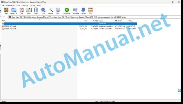
00 0303 987 4.pdf
00 0305 038 0.pdf
00 0305 038 0.pdf:
L55 MONTANAL54 MONTANAL53 MONTANA
Contents
1 Introduction
1.1 Notes regarding the instructions
1.1.1 Validity of the notice
2 Security
2.1 Safety marking on the machine
2.1.1 Power group warning pictogram
3 Description of the machine
3.1 Overview and mode of operation
3.1.1 MONTANA Overview
3.2 Nameplates and identification numbers
3.2.1 Drive axle nameplate
4 Control and display elements
4.1 Cabin and driving position
4.1.1 MONTANA control panel
4.2 CEBIS
4.2.1 Main menu item
4.2.2 Main menu item
5 Technical characteristics
5.1 L55 / L54 / L53 MONTANA
5.1.1 Machine dimensions
5.1.2 Machine dimensions
5.1.3 Dimensions of the hopper discharge tube in working position
5.1.4 Weight
Machine weight
Weight of the option
5.1.5 Sound pressure level and vibrations
5.1.6 Cummins L9 diesel engine
5.1.7 Cummins B6.7 diesel engine
5.1.8 Undercarriage
5.1.9 Tire pressure
5.1.10 Reference values for pulses per 100 m
5.1.11 Drive axle track gauge overview
5.1.12 Overview of steering axle track width
5.1.13 Lane width table 01
5.1.14 Lane width table 02
5.1.15 Lane width table 03
5.1.16 Lane width table 04
5.1.17 Lane width table 05
5.1.18 Lane width table 06
5.1.19 Brakes
5.2 Operating consumables
5.2.1 Lubricants
5.2.2 Hydraulic oils
6 Preparing the machine
6.1 Stop and immobilize the machine
6.1.1 Stop and immobilize the machine
6.2 Prepare the machine for travel
6.2.1 Prepare for road travel
6.2.2 Prepare to move into the field
6.3 Front tool
6.3.1 Adjusting the cutting angle with CEBIS
Set the cutting angle in the menu
Adjust the cutting angle in the favorites management menu
6.3.2 Manually adjust the cutting angle
6.3.3 Connecting and disconnecting the cutting angle automation
6.3.4 Activate cut e automation
6.4 Chassis
6.4.1 Place the machine on jack stands
6.4.2 Dismantling and installing the wheels
Remove the wheels
Install the wheels
6.4.3 Remove the transport swing stops from the steering axle
7.1 Driving the machine
7.1.1 Operating the machine
Move the machine forward
Brake the machine
Stop the machine
Move the machine in reverse
7.1.2 Bring the machine to the road travel position
7.1.3 Tow the machine out of the risk area
7.2 Tilt compensation
7.2.1 Secondary display area
7.2.2 Select the MONTANA axle regulation mode
Select axle regulation mode from the menu
Select axle regulation mode on secondary display area
7.2.3 Controlling MONTANA functions
7.2.4 Connecting and disconnecting the MONTANA control
7.2.5 Connecting and disconnecting MONTANA automatic mode
Connect the automatic mode of the MONTANA
Disconnect automatic mode from MONTANA
7.2.6 Connecting and disconnecting the MONTANA hand control
7.3 Chassis
7.3.1 Shift the gear electro-hydraulically
CEBIS display
7.4 Brake
7.4.1 Coupling and uncoupling the brake pedals
8 Faults and solutions
8.1 Slope compensation
8.1.1 Overview of MONTANA Automatic mode faults
8.2 Chassis
8.2.1 Overview of undercarriage failures
8.3 Transmission, clutch and cardan shaft
8.3.1 Mechanically shift the gearbox to neutral position
8.4 Brake
8.4.1 Mechanically release the parking brake
Put back into service
8.5 Power group
8.5.1 Overview of faults on the power unit
Learn Front Implement Height
9 Maintenance
9.1 Overview of maintenance frequencies
9.1.1 Before the start of the harvest
9.1.2 Every 10 operating hours or every day
9.1.3 Every 50 operating hours
9.1.4 Every 100 operating hours
9.1.5 Every 250 operating hours
9.1.6 Every 500 operating hours
9.1.7 Every 1000 operating hours
9.2 Lubrication plan
9.2.1 Lubricate the lubrication points
9.3 Chassis
9.3.1 Learn the front axle
9.3.2 Check the travel position on the road
9.3.3 Lubricate the pivot rings of the wheel connecting rods in accordance with the lubrication instructions
9.3.4 Check the oil level of the drive axle gearbox
9.3.5 Replacing the drive axle gearbox oil
Change the oil
Fill with oil
9.3.6 Check the oil level of the axle support of the drive axle
9.3.7 Replacing the oil in the axle support of the drive axle
Change the oil
Fill with oil
9.3.8 Check the oil level of the drive axle wheel connecting rods
9.3.9 Replacing the oil in the drive axle wheel connecting rods
Change the oil
Fill with oil
9.4 Brake
9.4.1 Checking the air bleeding of the brake cylinders
9.5 Power group
9.5.1 Check the basic cutting angle setting
9.5.2 Check the basic setting of the transverse position
9.5.3 Bleed the air from the hydraulic cylinders for transverse regulation of the front implement
9.6 Assembly parts and bodywork
9.6.1 Cleaning the machine
John Deere Repair Technical Manual PDF
John Deere Repair Technical Manual PDF
John Deere Diesel Engines PowerTech 4.5L and 6.8L – Motor Base Technical Manual 07MAY08 Portuguese
John Deere Parts Catalog PDF
John Deere Tractors 6300, 6500, and 6600 Parts Catalog CQ26564 (29SET05) Portuguese
John Deere Repair Technical Manual PDF
John Deere Repair Technical Manual PDF
John Deere Repair Technical Manual PDF
John Deere Parts Catalog PDF
John Deere Harvesters 8500 and 8700 Parts Catalog CPCQ24910 Spanish
John Deere Repair Technical Manual PDF
John Deere Repair Technical Manual PDF


