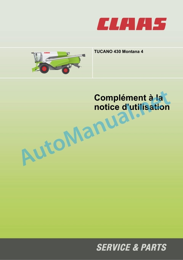
Claas Tucano 430 Montana 4 (831) Combines Operator Manual FR
$50.00
- Model: Tucano 430 Montana 4 (831) Combines
- Type Of Manual: Operator Manual
- Language: FR
- Format: PDF(s)
- Size: 52.6 MB
File List:
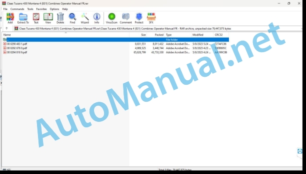
00 0290 483 1.pdf
00 0292 676 0.pdf
00 0294 818 9.pdf
00 0290 483 1.pdf:
Contents
1 Introduction
1.1 General advice
1.1.1 Validity of the notice
2 Overview
2.1 Assembled parts / Machine casing
2.1.1 Overview of the machine from the front and left
2.1.2 Overview of the rear and right side of the machine
2.1.3 Access to the driving position and maintenance points
3 Security
3.1 General advice
3.1.1 General safety instructions
3.1.2 Use in accordance with instructions
3.1.3 Clearly non-compliant use
3.1.4 Operation / use of Montana 4 slope compensation
3.1.5 Learn the Montana 4 end stops
3.1.6 Place the safety support in the supply channel
3.1.7 Remove the safety support from the supply channel
3.1.8 Install the safety supports on the variable height chassis
3.1.9 Remove the safety support from the variable height chassis
3.1.10 Lifting the machine using jacks
3.1.11 Load the machine and secure it
3.1.12 Decommissioning and disposal
3.2 Warning pictograms
3.2.1 Cabin / driving position
3.2.2 Chassis
3.2.3 Power group
3.2.4 Deposit of harvested product / deposition of straw
3.3 Safety sticker
3.3.1 Chassis safety supports with variable height
4 Technical characteristics
4.1 TUCANO 430 Montana 4 – Type 831
4.1.1 General advice
4.1.2 Motor
4.1.3 Chassis
4.1.4 Chassis tire pressure
4.1.5 Chassis, track
4.1.6 Brake
4.1.7 Management
4.1.8 Electrical/electronic system
4.1.9 Cabin / driving position
4.1.10 Power supply organs
4.1.11 Threshing bodies
4.1.12 Separation
4.1.13 Cleaning
4.1.14 Grain recovery
4.1.15 Grain recovery, dimensions
4.1.16 Dimensions of assembly parts / machine casing
4.1.17 Weight of assembly parts / machine casing
5 Before first commissioning
5.1 General advice
5.1.1 General warnings Before initial commissioning
5.1.2 Checklist for initial commissioning
5.2 Hydraulics
5.2.1 Check / fill the pressure accumulator (5008) for CLAAS AUTO CONTOUR II
6 Overview of control elements
6.1 General advice
6.1.1 General warnings Before initial commissioning
6.2 Cabin / driving position
6.2.1 Control console
6.2.2 Control panel Montana 4 control
6.2.3 Montana 4 command
6.3 Assembled parts / Machine casing
6.3.1 Access scale
7 Before each commissioning
7.1 General advice
7.1.1 General warnings Before initial commissioning
7.1.2 Checklist for daily start-up
9 Road driving and transport
9.1 General advice
9.1.1 General safety instructions Travel and transport
9.1.2 Preparing for driving on the road
9.1.3 Preparing for driving in the field
9.2 Axle frame
9.2.1 Advancement lever
9.2.2 Checking the functions of the Montana 4
9.2.3 Bring the machine to neutral position
9.2.4 Connect/disconnect Montana 4 automatic operation
9.2.5 Connect the Montana 4 hand control
9.2.6 CLAAS 4-Trac system
9.2.7 Connecting the CLAAS 4-Trac system
9.2.8 Disconnecting the CLAAS 4-Trac system
9.2.9 Towing the machine
9.3 Brake
9.3.1 Foot brake
9.3.2 Parking the machine
10 Setting for work
10.1 General advice
10.1.1 General work warning advice
10.2 Power unit
10.2.1 Adjust the feed fingers
13 Incidents and remedy
13.1 General advice
13.1.1 General warning tips Fault and solution
13.2 Axle frame
13.2.1 Adjust the rear axle linkage
13.2.2 Adjust the drive axle linkage
14 Maintenance
14.1 General advice
14.1.1 General warning advice Maintenance
14.2 Maintenance table
14.2.1 Maintenance frequencies
14.3 Lubricant table
14.3.1 Lubricants
14.4 Axle frame
14.4.1 Drive axle gearbox, clean surrounding area
14.4.2 Check the gearbox oil level
14.4.3 Drain the gearbox oil
14.4.4 Filling the gearbox with oil
14.4.5 Checking the oil level in the drive axle gearbox
14.4.6 Change the oil from the drive axle gearbox
14.4.7 Filling the drive axle gearbox
14.5 Brake
14.5.1 Adjusting the foot brake
14.5.2 Checking the brake pads / brake shoes
14.5.3 Replacing brake pads / brake shoes
14.6 Drive belts / drive chains
14.6.1 General safety advice
14.6.2 Left drive diagram TUCANO 430 Montana 4
14.6.3 Right side drive diagram TUCANO 430 Montana 4
14.6.4 Remove the belt (R1)
14.6.5 Install the belt (R1)
14.6.6 Belt adjustment (R1)
14.6.7 Remove the chain (K30)
14.6.8 Install the chain (K30)
14.6.9 Adjust the chain (K30)
14.6.10 Remove the chain (K60)
14.6.11 Install the chain (K60)
14.6.12 Adjust the chain (K60)
14.7 Hydraulics
14.7.1 Check the hydraulic system oil level
14.7.2 Replace hydraulic system oil/oil filter/air filter
14.7.3 Clean the hydraulic tank filling grid
14.8 Cabin / driving position
14.8.1 Cleaning the cabin windows
14.9 Power supply unit
14.9.1 Adjusting the feed chains
14.9.2 Adjusting the swivel frame
15 Lubrication plan
15.1 General advice
15.1.1 General warning tips lubrication scheme
15.2 Lubrication points
15.2.1 Fats
15.2.2 Lubrication intervals
15.2.3 Lubrication points – 10 o’clock left side
15.2.4 Lubrication points – 10 o’clock right side
15.2.5 Lubrication points – 100 h left side
15.2.6 Lubrication points – 100 h right side
Alphabetical index
00 0292 676 0.pdf:
LEXION 770 – 620TUCANO 470 – 320
Contents
1 About this user manual
1.1 General information
1.1.1 Validity of the notice
1.1.2 Symbols and instructions
2 Controls and displays
2.1 Cabin / Driving position
2.1.1 CEBIS control panel
2.2 CEBIS display
2.2.1 CEBIS general advice
2.2.2 Overview of the displacement indicator
2.2.3 Overview of the displacement indicator
2.2.4 Overview of the harvest indicator
2.2.5 CRUISE PILOT crop indicator overview
2.2.6 CEBIS direct menu overview
2.2.7 Respect CEBIS error code information
Respect type of error code information
Respect the structure of error code information
Classify error code information
View alarm history
View active alarms
2.2.8 Message box symbols
2.2.9 CEBIS direct menu
2.2.10 HOTKEY direct menu
2.2.11 Quick access menu
2.2.12 Main menu
2.2.13 Front tool menu
2.2.14 Driving menu
2.2.15 AUTO PILOT menu
2.2.16 Machine settings menu
2.2.17 Harvested product settings menu
2.2.18 Counter Menu
2.2.19 Maintenance menu
2.2.20 CEBIS menu
John Deere Repair Technical Manual PDF
John Deere Diesel Engines POWERTECH 2.9 L Component Technical Manual CTM126 Spanish
John Deere Repair Technical Manual PDF
John Deere Repair Technical Manual PDF
John Deere Repair Technical Manual PDF
John Deere Repair Technical Manual PDF
John Deere Repair Technical Manual PDF
John Deere PowerTech M 10.5 L and 12.5 L Diesel Engines COMPONENT TECHNICAL MANUAL CTM100 10MAY11
John Deere Parts Catalog PDF
John Deere Tractors 6300, 6500, and 6600 Parts Catalog CQ26564 (29SET05) Portuguese
John Deere Repair Technical Manual PDF


