Claas Variant 260 Rc (732) Baler Operator Manual ES
$50.00
- Model: Variant 260 Rc (732) Baler
- Type Of Manual: Operator Manual
- Language: ES
- Format: PDF(s)
- Size: 10.4 MB
File List:
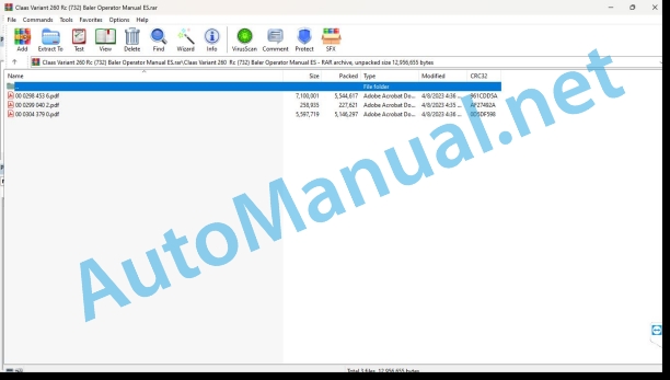
00 0298 453 6.pdf
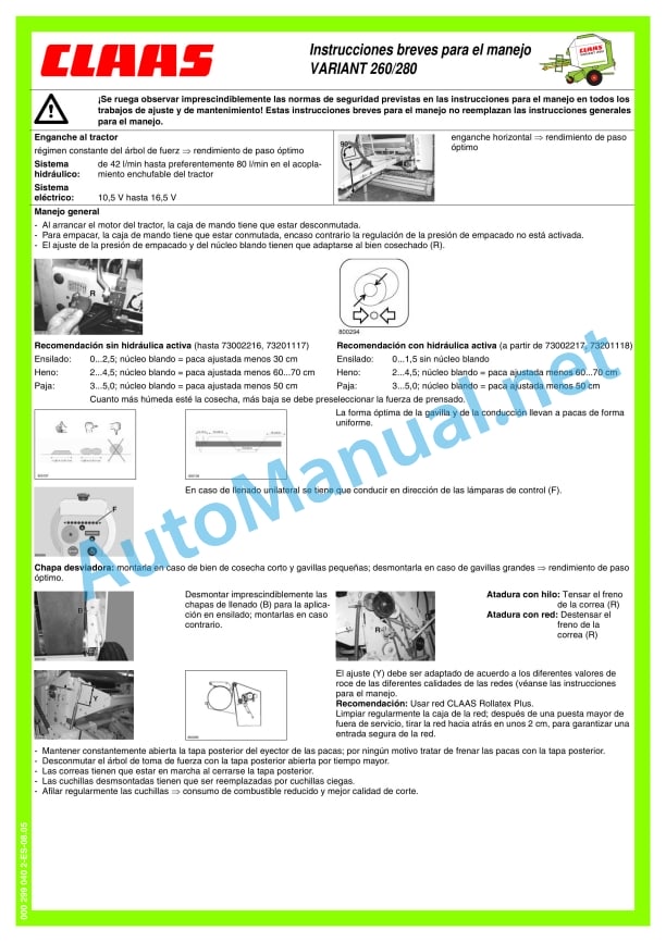
00 0299 040 2.pdf
00 0304 379 0.pdf
00 0298 453 6.pdf:
Introduction
Introduction
General indications
Road Traffic
Observe especially
Type indicator plate
Machine number
For security
For security
Warning and indication signs
Proper use
General safety and accident prevention requirements
Trailed machines
Service with PTO shaft
Hydraulic system
Maintenance
Machine working noises, information “D”
wheel chock
Fire extinguisher (Optional depending on country)
Main gear protective cover
Safety stickers with warning symbols
Technical characteristics
CLAAS Variant_x0011_260/280 / Variant_x0011_260/280_x0011_RC
Admission bodies
cutting device
Compaction of the pressed good
Tying mechanism
rolling wheels
Hydraulic system
Tractor hydraulic system required
Hydraulic pressure
Electric system
CLAAS Variant 260/280 /iant 260/280 RC
ensions of the round bale baler
CLAAS Variant 260/280 / Variant 260/280 RC
Safety devices
Cutting screws
Overload clutch
Configuration and way of working
Machine overview
Force transmission
Cutting coupling and free-running articulated shaft
Cam clutch articulated shaft
collecting drum
cutting device
Blind blade support (option)
pressing chamber
Tying the bales
bale ejector
Storage of round bales
Rotor Disengage Clutch
Rotor reverse turning device, manual
yarn drawer
Fire extinguisher (Optional depending on country)
Active hydraulics
Automatic chain lubrication
Address indication (option)
control box
Before commissioning
Check and observe before first start-up
Hook up the baler
Install the drive shaft on the machine side
Transmission shaft with tightening cone closure
Assemble the drive shaft with clamping cone lock
Stop support
Before unhitching the round baler
After attaching the round baler
Hook on the traction pendulum
Grease the traction eye
Mount the transmission shaft on the tractor side (by coupling with a traction pendulum)
Check the meshing of the drive shaft halves:
Reduce drive shaft
Secure the drive shaft protection tubes against simultaneous rotation
Hitch in the hitch mouth
Install the drive shaft on the tractor side
Attachment to the labeled pivot
Splice the pipes
handling box
Power supply
Translation lighting
Splice the hydraulic oil hoses
Back cover opening speed
Before transportation
Arrange the press
Collected
Pickup height adjustment
Adjust the working height of the pickup (pickup without support wheels)
Pickup with training wheels
Support wheels
Cutting device (VARIANT 260/280 RC)
blind blade
Assembling and disassembling the blades
Insert the blades into the blade holder
Fit the blade
Bale compaction
Pressing pressure regulation
Adjust the diameter of the bale
Adjust the diameter of the soft core
Net binding
Put the network
Regulate the number of network wraps
Tying with thread
Thread the thread
Regulate the number of thread wraps
Adjust the twine wraps on the outer edges of the bale
Tie with three threads
Prepare the eyelet for the thread
Introduce the three wires
Press adjustment for extreme silage cases
Removing the belt guides
Assembling the belt guides
Round bale press with twine and net tying
Switch to thread tying
Drive for tying with thread
Put the V-belt brake on
Switch to net tethering
Adjust the drive for tying with net
Release the V-belt brake
Silage pressing
Mount the blind knife holder (option) on VARIANT ROTO_x0011_CUT
Commissioning the round baler
Filling the pressing chamber
Indication of the direction of travel
Automatic binding
Tether delay
delay function
Thread Tying: Delay Adjustment
Net Tying: Delay Adjustment
Tying and ejecting the bales.
Deposit the bales
Ejecting bales without the bale ejector
bale counter
Round baler with net tying
Baler for round bales with twine and net tying
Round baler with twine tying
Manual overregulation of automatic fastening
Activate the binding process early
Slow down the binding process
Cutting device (ROTO CUT)
Turn the blades inward
Rotate the blades outward
Adjust the volume of the acoustic warning signal
Blockages in the round bale baler
Cam clutch articulated shaft
Rotor reverse turning device (VARIANT_x0011_260/280 / 260/280_x0011_RC)
Fault, reason or solution
Tying with thread
Net binding
After service
Uncouple the baler
wheel chocks
Stop support
control box
Hydraulic oil hoses and electrical connection cables
Transmission tree
Support wheels
Dirt cleaning
Maintenance
Important maintenance instructions
General maintenance instructions
Maintenance and lubrication tables
Maintenance tables
Lubricant table
Cutting screw, main drive
Cutting screw, collector drive
angular gear
Retension drive chains
Tension the collector drive chain
Tension the drive chain of the transverse conveyor thread
Adjust compression springs for pressure roller
Adjust the clamping device for the network meter
Adjust disc brakes
Tension the tension spring for the chain drive (belts and rotor)
Tension the tension spring for the chain drive on the rear cover
Adjust tension springs for clamping arm
Adjust the tension springs for the lower clamping arm
Tension the tension spring of the net roll braking bracket
Adjust spring cylinder for freewheel drive
Adjust the bale ejector tension springs
Adjust linkage to bale ejector end switch
Drive brake on twine tie
Adjust compression springs on disengagement clutches
Adjust the compression springs on the slip coupling (ratchet wheel) (attachment…
Adjust the thread tensioners
Inductive sensor settings
Inductive sensor “maximum ball diameter”
Inductive “door closed” sensor
Hydraulic oil filter (machines with filter installation)
Automatic chain lubrication
Adjust the Linatex guide plate
Fire extinguisher (option)
flat strap
Release the flat belt
Check flat belts
Repair flat belts
Lay the straps flat
Adjust the belt travel
Adjust the lower roller scraper
Check the seat of the wheel nuts
Check the wheel hub bearing clearance
Adjust bearing clearance
Proposals for preparing for winter
Lubrication plan
Lubricants and information
Reference word index
Reference word index
John Deere Repair Technical Manual PDF
John Deere Repair Technical Manual PDF
John Deere Repair Technical Manual PDF
John Deere POWERTECH E 4.5 and 6.8 L Diesel Engines TECHNICAL MANUAL 25JAN08
John Deere Repair Technical Manual PDF
John Deere DF Series 150 and 250 Transmissions (ANALOG) Component Technical Manual CTM147 05JUN98
John Deere Repair Technical Manual PDF
John Deere Repair Technical Manual PDF
John Deere PowerTech M 10.5 L and 12.5 L Diesel Engines COMPONENT TECHNICAL MANUAL CTM100 10MAY11
John Deere Repair Technical Manual PDF
John Deere Application List Component Technical Manual CTM106819 24AUG20
John Deere Repair Technical Manual PDF


