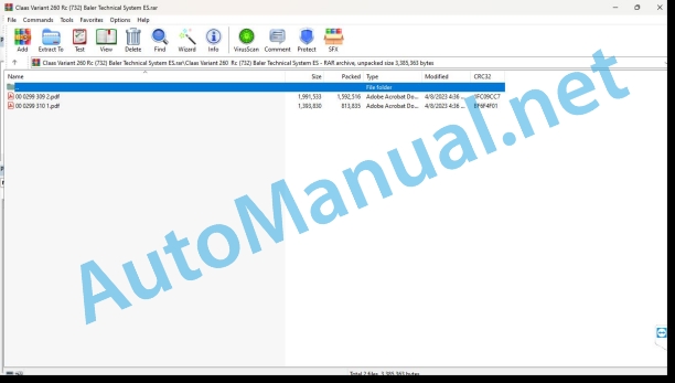
Claas Variant 260 Rc (732) Baler Technical System ES
$150.00
- Model: Variant 260 Rc (732) Baler
- Type Of Manual: Technical System
- Language: ES
- Format: PDF(s)
- Size: 2.3 MB
File List:
00 0299 309 2.pdf
00 0299 310 1.pdf
00 0299 309 2.pdf:
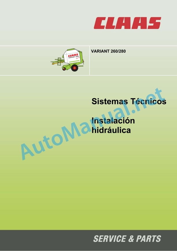
Technical Systems – VARIANT 260/280 hydraulic installation
Hydraulic installation index
Chapter 1 Connection diagram of the global hydraulic system
1.1 Connection diagram – without active hydraulic system
1.2 Connection diagram – with active hydraulic system, with built-in pressure maintenance valve (754) to machine no. …
1.3 Connection diagram – with active hydraulic system, without built-in pressure maintenance valve (754) from machine no. …
1.4 Wiring diagram – with active hydraulic system, main valve block 039 866.0 from machine no. 7300 3039 (V280), 7320 1875 (V260)
Chapter 2 Function
2.1 Function – without active hydraulics
2.2 Function – with active hydraulic system, with built-in pressure maintenance valve (754) up to machine no. …
2.3 Function – with active hydraulic system, without built-in pressure maintenance valve (754) from machine no.
2.4 Functiowactive hydraulic system, main valve block 039 866.0 from machine no. 7300 3039 (V280), 7320 1875 (V260)
Chapter 3 Valve Components
3.1 Main valve block – without active hydraulics
3.2 Pressing chamber shut-off valve (service) – without active hydraulics
3.3 Closing block (734)
3.4 Pressure limiting valve (754), pressing pressure increase solenoid valve (Y50) – without active hydraulic system
3.5 Flow regulator (755, 756)
3.6 Clutch rotor switch
3.7 Electromagnetic valve, ROTO CUT blade holder on/off. (Y54/Y55)
3.7.1 Electromagnetic valve, blade holder ROTO CUT on/off. (Y54/Y55) from machine no. 7300 2827
3.8 Main valve block – with active hydraulic system
3.8.1 Main valve block – with active hydraulics (from machine no. 7300 3039 V280, 7320 1875 V260)
Alphabetical index
0299 309.2
00 0299 310 1.pdf:
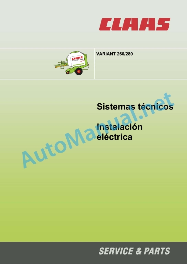
Electrical installation Variant 260/280
Assembly of the connection diagram
VARIANT 260/280 central electrical system
Module pin assignmenA) ModA19 Variant 260/280 without active hydraulic system (compare with the occupancy of modules B and C)
B) Module A19 Variant 260/280 with active hydraulic system (compare with the occupancy of modules A and C)
C) Module A19 Variant 260/280 with active hydraulic system (compare with the occupancy of modules A and B)
Module A67 – Linen tied module (RIO)
Fixing fuses and relays in the connection diagrams
01a – 26b
01a – Power supply to the main voltage system
05a – Terminal
06a – CAN-Bus, module voltage supply
06f – CAN-Bus, module power supply – with linen bundling
07a – Rotocut
10a – Pressing pressure regulation – without active hydraulic system
10b – Pressing pressure regulation – with active hydraulic system / with oil pressure switch Z17
10c – Pressing pressure regulation – with active hydraulic system / with oil pressure switch Z17 and tailgate closed sensor B135
11a – Activation of tying
11f – Activation of tying – tying linen
26a – Machine control – without active hydraulic system
26b – Machine control – with active hydraulic system / with oil pressure switch Z17 and maximum bale size sensor B137
cable trunk
Cable trunk A
Cable trunk B
Alphabetical index
0299 310.1
John Deere Repair Technical Manual PDF
John Deere Repair Technical Manual PDF
John Deere Application List Component Technical Manual CTM106819 24AUG20
John Deere Repair Technical Manual PDF
John Deere 18-Speed PST Repair Manual Component Technical Manual CTM168 10DEC07
John Deere Repair Technical Manual PDF
John Deere Repair Technical Manual PDF
John Deere Diesel Engines POWERTECH 2.9 L Component Technical Manual CTM126 Spanish
John Deere Repair Technical Manual PDF
John Deere 16, 18, 20 and 24HP Onan Engines Component Technical Manual CTM2 (19APR90)
John Deere Parts Catalog PDF
John Deere Harvesters 8500 and 8700 Parts Catalog CPCQ24910 Spanish
John Deere Repair Technical Manual PDF
John Deere Repair Technical Manual PDF
John Deere POWERTECH E 4.5 and 6.8 L Diesel Engines TECHNICAL MANUAL 25JAN08
John Deere Repair Technical Manual PDF


