Claas Variant 280 Rc (730) Balers Operator Manual EN
$50.00
- Model: Variant 280 Rc (730) Balers
- Type Of Manual: Operator Manual
- Language: EN
- Format: PDF(s)
- Size: 52.3 MB
File List:
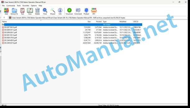
00 0297 943 6.pdf
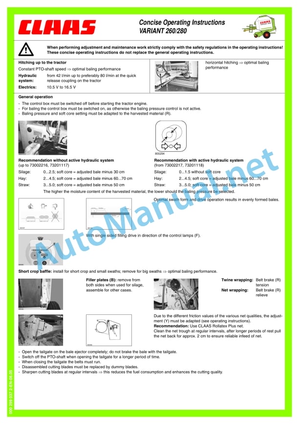
00 0299 037 2.pdf
00 0299 439 1.pdf
00 0301 051 0.pdf
00 0304 379 0.pdf
00 2348 408 0.pdf
00 2348 427 0.pdf
00 0297 943 6.pdf:
Introduction
Introduction
Contents
Contents
General notes
Road traffic
Important
Identification plate
Machine-number
Concerning safety
Concerning safety
Marking of warning and danger notes
Intended use
General safety and accident prevention _x0004_regulations
Hitched machines
Power take-off operation
Hydraulic system
Maintenance
Working noise of machines, Information D
Wheel chock
Fire extinguisher (country option)
Protection hood for main transmission
Safety stickers with warning symbol
Technical data
CLAAS Variant 260/280 / Variant 260/280 RC
Intake elements
Cutting device
Compression of bale material
Wrapping facility
Hydraulics
Required tractor hydraulics
Hydraulic pressure
Variant 260/280 / Variant 260/280 RC
Dimensions of the round baler
CLAAS Variant 260/280 / Variant 260/280 RC
Safety installations
Shearing screws
Overload clutch
Design and working principle
Machine overview
Power transmission
Shearing coupling and freewheeling propeller shaft
Cam clutch – propeller shaft
Cutting unit
Blanking knife holder (optional)
Baling chamber
Wrapping the bales
Bale ejector
Storage of round bales
Rotor switch-off clutch
Rotor reversing facility, manually
Twine boxes
Fire extinguisher (country option)
Active hydraulic system
Automatic chain lubrication
Direction indicator (optional)
Control box
Before starting operation
Check and observe the following before operating the machine
Hitching up the baler
Connecting the universal drive shaft to the baler
Propeller shaft with clamping taper lock
Installing propeller shaft with CC-lock
Parking support
Before hitching the round baler
After hitching the round baler
Hitching to the trailer coupling ring
Greasing the towing eye
Fitting the universal drive shaft to the tractor (for trailer coupling)
Checking the overlap of the universal drive shaft halves:
Shortening the universal drive shaft
Preventing the universal drive shaft guards from rotating with the drive shaft
Hitching to the towing hitch
Fitting the universal drive shaft to the tractor
Attaching to the ball head
Connecting the cables
Control box
Power supply
Travel lights
Connecting the hydraulic hoses
Tailgate opening speed
Before transport
Setting up the baler
Collecting
Height adjustment of pick-up
Adjusting the pick-up working height (Pick-up without supporting wheels)
Pick-up with support wheels
Support wheels
Cutting device (VARIANT 260/280_x0011_RC)
Blank knives
Installing and removing knives
Placing the knives into the dummy knife holder
Locking the knives
Pressing bales
Pressing pressure adjustment
Adjusting the bale diameter
Adjusting the soft core diameter
Wrapping
Net wrapping
Inserting the net
Adjusting the number of net windings
Twine wrapping
Threading the wrapping twine
Adjusting the number of twine windings
Adjusting the twine windings at the outer edges of the bale
Tying with three threads
Preparing the twine eyelet
Threading the three threads
Baler adjustment under severe silage conditions
Disassembly of belt guides
Installation of belt guides
Round baler with twine and net wrapping
Changing to twine wrapping
Adjusting the drive for twine wrapping
Applying the V-belt brake
Changing to net wrapping
Adjusting the drive for net wrapping
Releasing the V-belt brake
Pressing of silage
Installing the blank knife holder (optional) on VARIANT ROTO_x0011_CUT
Operation
Starting operation of the round baler
Filling the baling chamber
Travel direction indicator
Automatic wrapping
Tying delay
Delay function
Twine wrapping: Setting the delay
Net wrapping: Setting the delay
Wrapping and ejecting the bales
Laying down the bales
Ejecting bales without bale ejector
Bale counter
Round baler with net wrapping
Round baler with twine and net wrapping
Round baler with twine wrapping
Manual overload of the automatic wrapping
Triggering early wrapping
Delaying the wrapping process:
Cutting device (ROTO CUT)
Swashing the knives in
Swashing the knives out
Adjusting the volume of the audible warning signal
Blockage of the round baler
Cam clutch – propshaft
Rotor reversing facility (VARIANT_x0011_260/280_x0011_/_x0011_260/280_x0011_RC)
Fault, cause or remedy
Twine wrapping
Net wrapping
After use
Unhitching the baler
Wheel chocks
Parking support
Control box
Hydraulic hoses and electrical wiring
Propeller shaft
Gauge wheels
Cleaning of dirt
Maintenance
Important notes on maintenance
General notes on maintenance
Maintenance and lubricant charts
Maintenance table
Lubricant chart
Shearing bolt main drive
Shearing bolt pick-up drive
Angular gear
Tightening the drive chains
Tightening the pick-up drive chain
Tensioning the drive chain for the feed auger
Adjusting the pressure springs for the pressing roller
Adjusting the clamping device for the net knife
Adjusting the disc brake
Tightening the tension springs for the chain drive (belts and rotor)
Tightening the tension spring for the chain drive in the tailgate
Adjusting the tension springs for top tensioning arm
Adjusting the tension springs for bottom tensioning arm
Tightening the tension spring for the net roll braking bow
Adjusting the spring cylinder for freewheeling drive
Adjusting the tension springs of the bale ejector
Adjusting the linkage to the limit switch of the bale ejector
Drive brake for twine wrapping
Adjusting the pressure springs on the shut-off coupling
Adjusting the pressure springs on the friction clutch (ratchet wheel) (Net wrapping)
Adjusting the twine tensioner
Settings of the inductive sensors
Inductive sensor maximum ball diameter
Inductive sensor closed door
Hydraulic oil filter (Machines with filter system)
Automatic chain lubrication
Adjusting the Linatex guide plate
Fire extinguisher (optional)
Flat belts
Relieving the flat belts
Checking the flat belts
Repairing the flat belt
Installing the flat belt
Belt alignment
Adjusting the scraper, bottom roller
Check tight fit of wheel nuts
Checking wheel hub backlash
Adjusting the backlash
Proposals for winter storage
Lubrication plan
Lubricants and notes
Glossary
Glossary
pdf:
Notice de montage et d’utilisation
Kit lin – lin court and Kit Lin trs court
Introduction
Introduction
Consignes de scurit
Important
Characterization of indications sur les dangers
Consignes gnrales de scurit et de prvention des accidents
Stationnement de la machine
Utilization conforme la destination
Installation notice
Kit lin et lin court
Introduction
Lot de pices (0843 001.0)
Reduction of the number of belts
Dtente des courroies
Coupe des courroies
Ajustage de la longueur des corroies
Agrafage des courroies
Prparation du pick-up
Dmontage du tasseur
Dmontage du carter de protection du pick-up
Montage de la roue chain Kit lin
Dmontage des vis de recentrage
Remontage du carter du pick-up
Dmontage des dents du pick-up
Prparation dtectur de proximit
Graisseur
Montage du kit lin
Fixation du cadre prmont sur la presse
Montage du ski sur le cadre
Fixation du crochet sur la machine
Preparation of the Lin court kit
Variant 260
Perage de la chambre de pressage
Prmontage du kit lin court
Variant 280
Perage de la chambre de pressage
Prmontage du kit lin court
Guides-ficelle et couteau
Montage des guides-ficelle Lin
Montage du knife Lin
Dmontage du couteau d’origine
Montage du knife Lin
lectrique
Montage de l’interrupteur
Prparation de la tle
Fixation de l’interrupteur
Configuration du module pour le lin
Verification of information
Fixation du module lin sur le support
Montage du support sur la presse
Montage du faisce lectrique
Fixing the cable on thetting the proximity Introduction
Lot de pices (0843 592.0)
Prparation du kit lin trs court
Variant 260
Perage de la chambre de pressage
Prmontage du kit lin trs court
Variant 280
Perage de la chambre de pressage
Prmontage du kit lin trs court
Notice d’utilisation
Introduction
Principle and function
Vitesse de la prise de force
Pressage
Sens de pressage
Pressure de pressage
Liage des tiges de lin
Principle
Vitesse davancement et rapport de nappe
Avant utilization
Adjustment of the frame before the kit lin
Hauteur de la roue centrale
Hauteur des guides-fourrage
Hauteur du ski
Adjustment of the press
Nombre de tours de ficelle
Guides-ficelle Lin
Mise en place de la ficelle
Pre Diamtre de balls
pierreux
Rcolte sur terrain pierreux
Utilization pour le pressage du lin court
Generalities
Preparation of the pressing chamber
Montage des glissires sur la paroi – Variant 260
Montage des glissires sur la paroi – Variant 280
Mise en place de la tle lin court
Fixation de la tle lin court
Adjustment of the slide mobile
Rcolte sur terrain non pierreux
Rcolte sur terrain pierreux
Utilization pour le pressing du lin trs court
Generalities
Preparation of the pressing chamber
Montage des glissires sur la paroi – Variant 260
Montage des glissires sur la paroi – Variant 280
Mise en place de la tle lin trs court
Fixation de la tle lin trs court
Adjustment of the slide mobile
Rcolte sur terrain non pierreux
Rcolte sur terUse of the press for other harvests
y and operating instructions
Set linen – short line and set very short line
Introduction
Introduction
Safety instructions
The important information
Description of warning signs
General instructions on safety techniques and accident prevention
Car parking
Use as intended
Assembly instruction
Set for linen and short linen
Introduction
Lot of parts (0843 001.0)
Reducing the number of drive belts
Belt slack
Trimming belts
Belt length adjustment
Belt fastening
Preparing the baler
Dismantling the rammer
Dismantling the baler protection casing
Assembly of stars from the Len set
Dismantling of centering screws
Installation of the baler crankcase
Dismantling fingers with the baler
Preparing the on-board baler
Pre-assembly of the Len set
Installing wheelson a frame
Installation of feed guides on the frame
Setting the proximity detector
Lubrication hole
Assembling the Len set
Fastening the assembled frame to the press
Installing skis on a shoulder
Fixing the grip on the car
Preparation of the set Short linen
Variant 260
Perforating press camera
Pre-assembly of the Short Linen set
Variant 280
Perforating press camera
Pre-assembly of the Short Linen set
String guide and knife
Installation of the guide string of the Len set
Installation of the Len knife
Dismantling the standard blade
Installation of the Len knife
Electronics
Installation of the circuit breaker
Preparation sheet
Mounting the circuit breaker
Cleaning module setting
Check information
Fixation of the Len module on a support
Press support installation
Installation of electrical wiring
Fixing the cable to ng
Setting detector approximations
Hood installation
Assembly instruction
Set very short li592.0)
Preparation of the set Very short linen
Variant 260
Perforating press camera
Pre-assembly of the set Very Short Linen
Variant 280
Perforating press camera
Pre-assembly of the set Very Short Linen
Operating instructions
Introduction
Principle and operation
Power take-off speed
Pressing
Making presses
Pressure presses
Bundle of stems
A principle
Speed advances and layer coefficient
Preparation for use
Adjusting the front frame of the Len kit
Center wheel height
Height of feed guides
Ski height
Press setup
Number of windings
Guide cords Flax
Seasoning strings
Pressure presses
Bundle diameter
Use for pressing flax
Baler picker
Harvesting of non-rocky soil
Harvesting stony soil
Use for pressing short flaxf the press camera
Installation of guides on the wall – Variant 260
Installation of guides on the wall – Variant 280
Installation of welded sheet Short linen
Fixation of welded sheet Short flax
Adjustment of the movable guide
Harvesting of non-rocky soil
Harvesting stony soil
Use for pressing short flax
General information
Preparation of the press camera
Installation of guides on the wall – Variant 260
Installation of guides on the wall – Variant 280
Installation of welded sheet Very short linen
Fixation of welded sheet Very short linen
Adjustment of the movable guide
Harvesting of non-rocky soil
Harvesting stony soil
Using a press for harvesting other crops
Baler picker
Connection
Press camera
ctric current
Technical service
Lubrication hole
00 0301 051 0.pdf:
PROFI CAM 3
Table of contents
1 Introduction
1.1.1 Validity of manual
1.1.2 Information about this Operator’s Manual
1.1.3 Symbols and notes
1.1.4 Optional equipment
1.1.5 Qualified specialist workshop
1.1.6 Maintenance information
1.1.7 Warranty notes
1.1.8 Spare parts and technical questions
1.2 Intended use
1.2.1 Intended use
1.2.2 Reasonably foreseeable misuse
2 Safety
2.1 Identifying warnings
2.1.1 Hazard signs
2.1.2 Signal word
2.2 Safety rules
2.2.1 Meaning of Operator’s Manual
2.2.2 Observing safety decals and warnings
2.2.3 Optional equipment and spare parts
3 Product description
3.1 Overview and method of operation
3.1.1 How the PROFI CAM works
3.2 Identification plates and identification number
3.2.1 Position of identification plates
3.2.2 Explanation of PROFI CAM identification plate
3.3 Information on the product
3.3.1 CE marking
4 Operating and control elements
4.1 Camera system
4.1.1 Camera system monitor
4.2 Menu structure
4.2.1 Main menu
4.2.2
4.2.3
4.2.4
4.2.5
4.2.6
5 Technical specifications
5.1 PROFI CAM
5.1.1 Monitor
5.1.2 Camera
5.1.3 Switch box
5.1.4 Degree of protection against foreign bodies and water
6 Preparing the product
6.1 Shutting down and securing the machine
6.1.1 Switching off and securing the machine
6.2 Prior to operation
6.2.1 Carry out prior to operation
6.2.2 Installing the sun protection
6.2.3 Aligning the camera
6.2.4 Connecting the camera electrics
7 Operation
7.1 Monitor
7.1.1 Switching on the monitor
7.1.2 Calling up the menu
7.1.3 Setting a menu item
7.1.4 Setting the image orientation
7.1.5 Setting automatic screen darkening
7.1.6 Image mirroring
7.1.7 Setting the trigger view
7.1.8 Setting the follow-up time for trigger view
7.1.9 Setting the display mode
7.1.10 Activating/deactivating a display mode
8 Faults and remedies
8.1 Electrical and electronic system
8.1.1 Overview of problems on PROFI CAM camera system
8.1.2 Replacing the switch box fuse
9 Maintenance
9.1 Maintenance intervals
9.1.1 Every 10 operating hours or daily
9.2 Camera system
9.2.1 Checking the camera system for dirt
9.2.2 Cleaning the camera
9.2.3 Cleaning the switch box
9.2.4 Cleaning the monitor
10 Placing out of operation and disposal
10.1 General Information
10.1.1 Putting out of operation and disposal
11 Technical terms and abbreviations
11.1 Abbreviations
11.1.1 Units
11.1.2 Abbreviations
11.1.3 Technical terms
00 2348 408 0.pdf:
CEMIS 100
Table of contents
1 Introduction
1.1 General information
1.1.1 Validity of the manual
1.1.2 Information about this Operator’s Manual
1.1.3 Symbols and notes
1.2 Intended use
1.2.1 Intended use
1.2.2 Reasonably foreseeable misuse
2 Safety
2.1 Safety rules
2.1.1 General safety and accident prevention regulations
2.1.2 Interaction between terminal and machine or tractor
2.1.3 Electrocution by electrical system
3 Product description
3.1 Overview and method of operation
3.1.1 Overview of CEMIS 100
3.1.2 Function principle of CEMIS 100
3.2 Identification plates and identification numbers
3.2.1 Spare parts and technical questions
3.2.2 Identification plate of CEMIS 100
4 Operating and display elements
4.1 CEMIS 100
4.1.1 User interface for LINER
4.1.2 User interface for ROLLANT
4.1.3 User interface for UNIWRAP
5 Technical specifications
5.1 CEMIS 100
5.1.1 Specification
6 Operation
6.1 CEMIS 100
6.1.1 Operating the CEMIS 100
6.1.2 Switching CEMIS 100 on
6.1.3 Switching CEMIS 100 off
7 Maintenance
7.1 CEMIS 100
7.1.1 Daily
8 Putting out of operation and disposal
8.1 General information
8.1.1 Removal from service and disposal
9 Technical terms and abbreviations
9.1 Terms and explanations
9.1.1 Technical words
9.1.2 Abbreviations
00 2348 427 0.pdf:
CEMIS 700
Table of contents
1 Introduction
1.1 General information
1.1.1 Validity of the manual
1.1.2 Information about this Operator’s Manual
1.1.3 Symbols and notes
1.2 Intended use
1.2.1 Intended use
1.2.2 Reasonably foreseeable misuse
2 Safety
2.1 Safety rules
2.1.1 General safety and accident prevention regulations
2.1.2 Interaction between terminal and machine or tractor
2.1.3 Electrocution by electrical system
3 Product description
3.1 Overview and method of operation
3.1.1 Overview of CEMIS 700
3.1.2 Function principle of CEMIS 700
3.2 Identification plates and identification numbers
3.2.1 Spare parts and technical questions
3.2.2 Identification plate of CEMIS 700
4 Information on the product
4.1 Software version
5 Operating and display elements
5.1 CEMIS 700
5.1.1 User interface
5.1.2 Terminal program
6 Technical specifications
6.1 CEMIS 700
6.1.1 Specification
7 Operation
7.1 CEMIS 700
7.1.1 Operating the CEMIS 700
7.1.2 Switching CEMIS 700 on
7.1.3 Switching CEMIS 700 off
7.2 Terminal settings
7.2.1 Making settings
Making settings with the rotary button
Making settings with the touch function
7.2.2 Setting the screen lighting
Daytime mode
Nighttime mode
Activating automatic key lighting
7.2.3 Setting the time and date
7.2.4 Displaying diagnosis information
On-board power supply voltage display
Display of CLAAS ISOBUS ECU address and name
7.2.5 Setting the language and display formats
Setting the language
Setting display formats
7.2.6 Setting the volume
7.2.7 Deleting an ISOBUS implement
8 Maintenance
8.1 Maintenance
8.1.1 Daily
9 Putting out of operation and disposal
9.1 General information
9.1.1 Removal from service and disposal
10 Technical terms and abbreviations
10.1 Terms and explanations
10.1.1 Technical words
10.1.2 Abbreviations
John Deere Repair Technical Manual PDF
John Deere Diesel Engines POWERTECH 2.9 L Component Technical Manual CTM126 Spanish
John Deere Repair Technical Manual PDF
John Deere Transmission Control Unit Component Technical Manual CTM157 15JUL05
John Deere Repair Technical Manual PDF
John Deere Repair Technical Manual PDF
John Deere Parts Catalog PDF
John Deere Harvesters 8500 and 8700 Parts Catalog CPCQ24910 Spanish
John Deere Repair Technical Manual PDF
John Deere Repair Technical Manual PDF
John Deere Repair Technical Manual PDF
John Deere Repair Technical Manual PDF
John Deere PowerTech M 10.5 L and 12.5 L Diesel Engines COMPONENT TECHNICAL MANUAL CTM100 10MAY11

