Claas Variant 350 (770) Balers Assembly Instruction EN
$50.00
- Model: Variant 350 (770) Balers
- Type Of Manual: Assembly Instruction
- Language: EN
- Format: PDF(s)
- Size: 97.6 MB
File List:
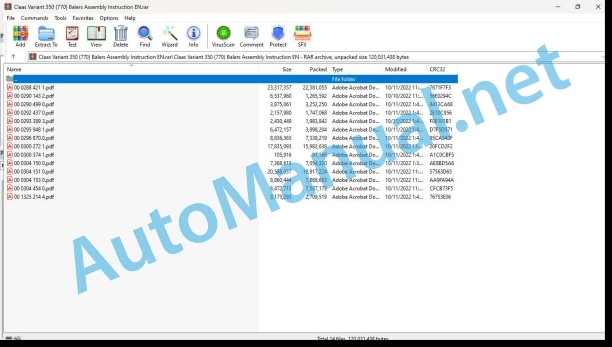
00 0288 421 1.pdf
00 0290 143 2.pdf
00 0290 499 0.pdf
00 0292 437 0.pdf
00 0293 389 3.pdf
00 0295 948 1.pdf
00 0296 870.0.pdf
00 0300 272 1.pdf
00 0300 374 1.pdf
00 0304 150 0.pdf
00 0304 151 0.pdf
00 0304 153 0.pdf
00 0304 454 0.pdf
00 1325 214 4.pdf
00 0288 421 1.pdf:
Assembly instructions
Table of contents
1 To this manual
1.1 General information
1.1.1 General points
1.1.2 Machines that can be equipped
2 Safety
2.1 General information
2.1.1 General points
2.1.2 Use in accordance with the original specifications
2.2 Safety instructions
2.2.1 Definition of hazard information
2.2.2 General safety and accident prevention advice
2.2.3 Parking the machine
3 Bill of material
3.1 Parts kit
3.1.1 Tying feed plate VARIANT
Kit 00 1349 390 3
4 Mounting
4.1 Introduction
4.1.1 General points
4.1.2 Securing the baler
4.1.3 Tightening torques
4.2 Machine preparation
4.2.1 Preparing the machine
Removing the tying feed lips
4.3 Fitting the kit
4.3.1 Fitting the guide plate stop
Assembly <1>
Checking the hydraulic block support
Drilling the support
Fitting the stop
Assembly <2>
Checking the hydraulic block
Fitting the stop
Assembly <3>
Checking the hydraulic block support
Fitting the stop
4.3.2 Fitting the guide plate
Checking the flat section
Adjusting the position of the spring
Drilling the flat section
Fit the guide plate
Adjusting the guide plate position
4.3.3 Fitting the protective tube
Modifying the protective tube
Finishes
Fit the protective tube
4.3.4 Testing the machine
Adjusting the guide plate position
00 0290 499 0.pdf:
1 Introduction
1.1 General information
1.2 Equipped machines
2 Security signs
2.1 Important
2.1.1 General information
2.1.2 Utilization compliant with the destination
2.2 Safety notices
2.2.1 Characterization of the indications on the dangers
2.2.2 General signs for safety and prevention of accidents
2.2.3 Stationing the machine
3 Lots of pieces
3.1 Rouleau kit N_x001E_ 5 – 4 courroies – 00 0857 297 0
3.2 Rouleau kit N_x001E_ 5 – 5 courroies – 00 0857 298 0
4 Assembly instructions
4.1 Introduction
4.1.1 General information
4.2 Dpose du rouleau N 5
4.2.1 Press security
4.2.2 Preparation of the press
4.2.3 Dpose du rouleau N 5
4.3 Reassembly of the machine
4.3.1 Remontage rouleau N_x001E_ 5
4.3.2 Remontage de l’entranement
4.3.3 Function tests
5 Grass plan
5.1 Graissage de la presse
5.2 Greasing points
5.2.1 Greases and oils of lubrication
5.2.2 Greasing intervals
5.3 Graissage manual de la presse
5.3.1 Ct left – every 10 hours
5.3.2 Ct droit – toutes les 10 h
1 Einleitung
1.1 Allgemeines
1.2 Auszurstende Maschinen
2 Sicherhriften
2.1 Wichtig
2.1.1 Allgemein Sicherheitsvorschriften
2.2.1 Kennzeichnung der Gefahrenhinweise
2.2.2 Allgemeine Vorschriften zur Sicherheit und Unfallverhtung
2.2.3 Parking of the Machine
3 Stckliste
3.1 Set fr Walze Nr. 5 – 4 Bands – 00 0857 297 0
3.2 Set fr Walze Nr. 5 – 5 Bands – 00 0857 298 0
4 Anbauanleitung
4.1 Einleitung
4.1.1 Allgemeines
4.2 Ausbau der Walze Nr. 5
4.2.1 Sichern der Presse
4.2.2 Vorbereiten der Presse
4.2.3 Ausbau der Walze Nr. 5
4.3 Assembly of the machine
4.3.1 Walze Nr. 5 wieder einbauen
4.3.2 Zusammenbau des Antriebs
4.3.3 Funktionstest
5 Schmierplan
5.1 Schmierung der Presse
5.2 Schmierpunkte
5.2.1 Schmierfette and Schmierle
5.2.2 Schmier interval
5.3 Manuelle Schmierung der Presse
5.3.1 Linke Seite – at 10 am
5.3.2 Right Page – at 10 am
1 Introduction
1.1 General points
1.2 Machines that can be fitted
2 Safety advice
2.1 Impor 2.1.1 General points
2.1.2 Use in accordance with original specificatioons
2.2.1 Definition of hazard information
2.2.2 General safety and accident prevention advice
2.2.3 Parking the car
3 Parts kit
3.1 Roller kit no. 5 – 4 belts – 00 0857 297 0
3.2 Roller kit no. 5 – 5 belts – 00 0857 298 0
4 Assembly instructions
4.1 Introduction
4.1.1 General points
4.2 Removing roller no. 5
4.2.1 Securing the baler
4.2.2 Preparing the baler
4.2.3 Removing roller no. 5
4.3 Reassembling the machine
4.3.1 Refitting roller no. 5
4.3.2 Refitting the drive
4.3.3 Operating tests
5 Lubrication plan
5.1 Greasing the baler
5.2 Lubrication points
5.2.1 Lubricating oils and grease
5.2.2 Lubrication intervals
5.3 Manual lubrication of the baler
5.3.1 Left-hand side – every 10 hours
5.3.2 Right-hand side – every 10 hours
1. Introduction
1.1 General information
1.2 Machines to be equipped
2 Safety instructions
2.1 Important
2.1.1 General information
2.1.2 Intended use
2.2 Safety instructions
2.2.1 Characterization of hazard statements
2.2.2 General safety and accident prevention instructions
2.2.3 Parking of the machine
3 Lot of pieces
3.1 Roller kit N_x001E_ 5 – 4 belts – 00 0857 297 0
3.2 Roller kit N_x001E_ 5 – 5 belts – 00 0857 298 0
4 Assembly instructions
4.1 Introduction
4.1.1 General information
4.2 Removing the roller N_x001E_ 5
4.2.1 Securing the press
4.2.2 Preparation of the press
4.2.3 Removing the N_x001E_ 5 roller
4.3 Reassembly of the machine
4.3.1 Reassembling roller N_x001E_ 5
4.3.2 Reassembly of the transmission
4.3.3 Operational test
5 Lubrication plan
5.1 Lubrication of the press
5.2 Lubrication points
5.2.1 Greases and lubricating oils
5.2.2 Lubrication intervals
5.3 Manual lubrication of the press
5.3.1 Left side – every 10 hours
5.3.2 Right side – every 10 hours
1 Introduction
1.1 General information
1.2 Applicable machines
2 Safety regulations
2.1 Important
2.1.1 General information
2.1.2 Use in accordance with the application
2.2 Safety regulations
2.2.1 Symbols applicable to the safety indications
2.2.2 General safety and accident prevention regulations
2.2.3 Fijacin de la mquina
3 Lots of piezas
3.1 Roller kit n._x001E_ 5 – 4 correas – 00 0857 297 0
3.2 Roller kit n._x001E_ 5 – 5 correas – 00 0857 298 0
4 Assembly manual
4.1 Introduction
4.1.1 General information
4.2 Disassembly of the rod n._x001E_ 5
4.2.1 Fijacin de la prensa
4.2.2 Preparation of the packing
4.2.3 Disassemble the rod n._x001E_ 5
4.3 Return to assembling the machine
4.3.1 Turn to fit the rod n._x001E_ 5
4.3.2 Assembly of the gear
4.3.3 Operational procedure
5 Plan de engrase
5.1 Engaging the empacadora
5.2 Entry points
5.2.1 Greases and lubricating oils
5.2.2 Engaging intervals
5.3 Manually insert the mixer
5.3.1 Left alone, every 10 hours
5.3.2 Right side, e 10 hours
1.2 g 2.2
3.1 g0 – VARIANT 370 – VARIANT 380: 0843 730.2
3.2 Pressen mit 4 Riemen
3.2.1 VARIANT 360 – VARIANT 365: 0843 745.2
3.2.2 VARIANT 380 – VARIANT 385: 0843 746.2
4 Assembly of new Riemens
4.1 Ben?tigtes Material
4.1.1 Materials, materials and materials
4.1.2 Unterlagen
4.2 Press comments
4.2.1 Press information
4.2.2 Die entspannen
4.2.3 Abnehmen des besch?digten Riemens
4.3 Protection of new Riemens
4.3.1 Positioning of the sockets in Riemen – VARIANT 260/280/350/370/360/380 – Pressen mit 5 Riemen
4.3.2 Positioning of the sockets in Riemen – VARIANT 360/365/380/385 – Pressen mit 4 Riemen
4.3.3 Einstzen eines neuen Riemens
4.3.4 Festivals of Riemens
4.3.5 Reinstatement of the exposed flange
4.3.6 Vorkleben
4.3.7 Kleben
4.3.8 Trocknungszeit
4.4 Press releases
4.4.1 Austausch eines Riemens
4.4.2 Austausch von 2 oder mehr Riemen
1 Introduction
1.1 General points
1.2 Machines that can be fitted
2 Safety advice
2.1 Important
2.1.1 General points
2.1.2 Use in accordance with original specifications
2.2 Safety instructions
2.2.1 Definition of hazard information
2.2.2 General safety and accident prevention advice
2.2.3 Parking the machine
3 Parts kit
3.1 5 belt balers
3.1.1 VARIANT 260 – VARIANT 350 – VARIANT 360: 0843 732.2
3.1.2 VARIANT 280 – VARIANT 370 – VARIANT 380: 0843 730.2
3.2 4 belt balers
3.2.1 VARIANT 360 – VARIANT 365: 0843 745.2
3.2.2 VARIANT 380 – VARIANT 385: 0843 746.2
4 Fitting a new belt
4.1 Equipment necessary
4.1.1 Safety, cleaning and bonding materials
4.1.2 Support equipment
4.2 Preparing the baler
4.2.1 Securing the baler
4.2.2 Loosening the belts
4.2.3 Removing the damaged belt
4.3 Fitting the new belt
4.3.1 Positioning the bonded belts – VARIANT 260 / 280 / 350 / 370 / 360 / 380 – Balers fitted with 5 belts
4.3.2 Positioning bonded belts – VARIANT 360 / 365 / 380 / 385 – Balers fitted with 4 belts
4.3.3 Fitting a new belt
4.3.4 Affixing the belt
4.3.5 Cleaning the surfaces to be bonded
4.3.6 Pre-bonding
4.3.7 Bonding
4.3.8 Curing time
4.4 Returning the baler to use
4.4.1 Changing a belt
4.4.2 Replacing 2 belts or more
1 Introduction
1.1 General
1.2 Machines to be equipped
2 Safety instructions
2.1 Important
2.1.1 General
2.1.2 Use as intended
2.2 Safety instructions
2.2.1 Characterization of hazard indications
2.2.2 General safety and accident prevention instructions
2.2.3 Parking the machine
3 Lot of parts
3.1 5-belt presses
3.1.1 VARIANT 260 – VARIANT 350 – VARIANT 360: 0843 732.2
3.1.2 VARIANT 280 – VARIANT 370 – VARIANT 380: 0843 730.2
3.2 4-belt presses
3.2.1 VARIANT 360 – VARIANT 365: 0843 745.2
3.2.2 VARIANT 380 – VARIANT 385: 0843 746.2
4 Fitting a new belt
4.1 Necessary equipment
4.1.1 Safety equipment, cleaning and bonding
4.1.2 Support material
4.2 Press preparation
4.2.1 Securing the press
4.2.2 Belt relaxation
4.2.3 Removing the damaged belt
4.3 Assembling the new belt
4.3.1 Positioning of glued belts – VARIANT 260 / 280 / 350 / 370 / 360 / 380 – Presses equipped with 5 belts
4.3.2 Positioning the glued belts – VARIANT 360 / 365 / 380 / 385 – Presses equipped with 4 belts
4.3.3 Inserting a new belt
4.3.4 Attaching the belt
4.3.5 Cleaning the surfaces to be glued
4.3.6 Pre-gluing
4.3.7 Gluing
4.3.8 Drying time
4.4 Returning the press to service
4.4.1 Changing a belt
4.4.2 Changing 2 or more belts
1 Introduction
1.1 General information
1.2 Applicable machines
2 Safety standards
2.1 Important
2.1.1 General information
2.1.2 Use in accordance with the application
2.2 Safety standards
2.2.1 Symbols applicable to battery indications
2.2.2 General safety and accident prevention standards
2.2.3 Fitting the machine
3 Lots of pieces
3.1 Empacadoras de 5 correas
3.1.1 VARIANT 260 – VARIANT 350 – VARIANT 360: 0843732.2
3.1.2 VARIANT 280 – VARIANT 370 – VARIANT 380: 0843730.2
3.2 Empacadoras de 4 correas
3.2.1 VARIANT 360 – VARIANT 365: 0843745.2
3.2.2 VARIANT 380 – VARIANT 385: 0843746.2
4 Adjustment of a new belt
4.1 Necessary materials
4.1.1 Safety, cleaning and packaging materials
4.1.2 Material of ayuda
4.2 Preparing the package
4.2.1 Connection of the device
4.2.2 Loading of correas
4.2.3 Removing the damaged belt
4.3 Climbing the new belt
4.3.1 Positioning of the pegged correas – VARIANT 260/280/350/370/360/380 – Packed with 5 correas
4.3.2 Positioning the pegged correas – VARIANT 360/365/380/385 – Packed with 4 correas
4.3.3 Introduction of a new correa
4.3.4 Attachment of the correa
4.3.5 Cleaning the coating surfaces
4.3.6 Pre-encolado
4.3.7 Encolado
4.3.8 Dry time
4.4 Start of the machine
4.4.1 Substitution of a correa
4.4.2 Substitution of 2 or more correas
00 0295 948 1.pdf:
VARIANT 350VARIANT 370/370POWERVARIANT 360/360RC/365RCVARIANT 380/380RC/385RC
Inhaltsverzeichnis
Table of contents
Table of materials
Cast of the content
Spis tresci
1 Zu dieser Anleitung
1.1 Allgemeine Hinweise
1.1.1 Allgemeines
1.1.2 Auszurstende Maschinen
2 Sicherheit
2.1 Allgemeine Hinweise
2.1.1 Allgemeines
2.1.2 Benutzung gem Zweckbestimmung
2.2 Sicherheitsvorschriften
2.2.1 Kennzeichnung der Gefahrenhinweise
2.2.2 Allgemeine Vorschrifrheit und Unfallverhtung
2.2.3 Parken der Maschine
3 Stckliste
3.1 Teilesatz
3.1.1 Rollenniederhalter
Teilesatz 00 0844 901 1
4.1 Maschine vorbereiten
4.1.1 Sichern der Presse
4.1.2 Sicheres Arbeiten
4.1.3 Ausbau des Kurzstrohprallblechs (wenn vorhanden)
4.1.4 Ausbau des Schutzrohres und des Niederhalters
4.2 Satz anbauen
4.2.1 Anzugsdrehmomente
4.2.2 Vorbereitung des Rollenniederhalters
4.2.3 Einbau des Rollenniederhalters
4.2.4 Checking the upper Anschlge
4.2.7 Sicherheitsaufkleber
4.2.8 Einstellung des Rollenniederhalters
1 To this manual
1.1 General Information
1.1.1 General points
1.1.2 Machines that can be equipped
2 Safety
2.1 General Information
2.1.1 General points
2.1.2 Use in accordance with the original specifications
2.2 Safety instructions
2.2.1 Definition of hazard information
2.2.2 General safety and accident ption advice
2.2.3 Parking the machine
3 Bill of material
3.1 Parts kit
3.1.1 Roller crop press
Kit 00 0844 901 1
4 Mounting
4.1 Machine preparation
4.1.1 Securing the baler
4.1.2 Working safely
4.1.3 Removing the short crop baffle plate (depending on equipment)
4.1.4 Removing the guard and the crop guard
4.2 Fitting the kit
4.2.1 Tightening torques
4.2.2 Preparing the roller crop press
4.2.3 Fitting the roller crop press
4.2.4 Fitting the upper stops
4.2.5 Moving the shock absorb pads
4.2.6 Attaching the retaining chains
4.2.7 Safety sticker
4.2.8 Adjusting the roller crop press
1 About this notice
1.1 General information
1.1.1 Generalities
1.1.2 Machines by equipment
2 Security
2.1 General information
2.1.1 Generalities
2.1.2 Use according to the destination
2.2 Security instructions
2.2.1 Characterization of indications on dangers
2.2.2 General safety and accident prevention instructions
2.2.3 Machine stationing
3 Nomenclature
3.1 Lot of parts
3.1.1 Rouleau abaisseur
Kit 00 0844 901 1
4 Montage
4.1 Preparation of the machine
4.1.1 Press security
4.1.2 Security worker
4.1.3 Disposal of the court’s tle paille (selon quipement)
4.1.4 Disposal of warranty and security
4.2 Pose of the kit
4.2.1 Couples of suede
4.2.2 Preparation of the abaisseur roller
4.2.3 Pose du rouleau abaisseur
4.2.4 Pose des butes suprieures
4.2.5 Decalage of the amortisseur pads
4.2.6 Fixing the retaining chains
4.2.7 Security autocollant
4.2.8 Rglagebout this manual
1.1 General data
1.1.1 General information
1.1.2 Machines to equip
2 Security
2.1 General data
2.1.1 General information
2.1.2 Use according to the application
2.2 Safety regulations
2.2.1 Symbols applicable to danger indications
2.2.2 General safety and accident prevention rules
2.2.3 Fixing the machine
3 Nomenclature
3.1 Lot of parts
3.1.1 er roller
Kit 00 0844 901 1
4 Assembly
4.1 Machine preparation
4.1.1 Baler protection
4.1.2 Work in safe conditions
4.1.3 Disassembly of the short straw plate (depending on equipment)
4.1.4 Disassembly of the protection tube and the compactor
4.2 Kit placement
4.2.1 Tightening torques
4.2.2 Preparation of the reduction roller
4.2.3 Assembly of the reduction roller
4.2.4 Assembly of the upper stops
4.2.5 Misalignment of the shock absorber plugs
4.2.6 Fixing the retaining chains
4.2.7 Safety sticker
4.2.8 Adjustment of the reduction roller
1 Information on this manual
1.1 General information
1.1.1 General information
1.1.2 Equipment machine
2 Sicurezza
2.1 General information
2.1.1 Generalita
2.1.2 Use according to destination
2.2 Safety requirements
2.2.1 Characteristics of the indications relative to the pericoli
2.2.2 General safety and incident prevention instructions
2.2.3 Machine station
3 Nomenclature
3.1 Lotto di pezzi
3.1.1 Roll compensator
Kit 00 0844 901 1
4 Montaggio
4.1 Preparation of the machine
4.1.1 Messa in security of the pressa
4.1.2 Lavorare in security
4.1.3 Smontage of the short paglia lamiera (a seconda dell’equipaggiamento)
4.1.4 Removal of the protection tube and pettine
4.2 Assembly of the kit
4.2.1 Serraggio copy
4.2.2 Preparation of the roller compensator
4.2.3 Mounting the compensator to roller
4.2.4 Montaggio dei finecorsa superiori
4.2.5 Storage of memory pads
4.2.6 Fixing catene di trattenuta
4.2.7 Safety adhesive
4.2.8 Adjustment of the compensator to roller
1 Informacje dotyczce tej instrukcji
1.1 Wskazwki oglne
1.1.1 Ogolne information
1.1.2 Maszyny dostosowane do montau zestawu
2 Bezpieczestwo
2.1 Wskazwki oglne
2.1.1 Ogolne information
2.1.2 Uytkowanie zgodnie z przeznaczeniem
2.2 Zalecenia dotyczce bezpieczestwa
2.2.1 Charakterystyka oznacze wskazujcych na zagroenia
2.2ecenia dotyczce bezpieczestwa i zapobiegania wypadkom
2.2.3 Parkowanie maszyny
3 Wykaz elementw
3.1 Zestaw czci
3.1.1 Waek obniajcy
Zestaw 00 0844 901 1
4 Doczanie
4.1 Przygotowanie maszyny
4.1.1 Zabezpieczenie prasy
4.1.2 Zasady bezpiecznej pracy
4.1.3 Demonta blachy uderzeniowej do krtkiego material (zalenie od wyposaenia)
4.1.4 Demonta osony zabezpieczajcej i zgniatacza
4.2 Monta zestawu
4.2.1 Momenty dokrcaniach
4.2.6 Mocowanie acuchw przytrzymujcych
4.2.7 Naklejka bezpieczestwa
4.2.8 Regulacja waka obniajcego
1 this this instruction
1.1 General use
1.1.2 Disabled machines
2 Blessedness
2.1 General use
2.1.1 Overview
2.1.2 Ispolzovanie >?0A=>AB8
2.2.2 Instructions for uselessness and non-useful use
2.2.3 Machine storage
3 Nomenclature
3.1 Complete details
3.1.1 Setting the value
Complete 00 0844 901 1
4 Ustanovka
4.1 Power the machine
4.1.1 _x001F_@82545=85 ?@5AA-?>41>@I8:0 2 157>?5=85 A>AB>O=85
4.1.2 !>1;N45=85 B5E=8:8 bezopassnosti
4.1.3 Disassembly of the panels of the short sections only (in their completeness i)
4.1.4 Disassembly of pre- and C?;>B=8B5;O
4.2 Installation of the complex
4.2.F5?59
4.2.7 Nails without trebovaniami
4.2.8 53C;8@>2:0 ?>=860NI53> 20;:0
00 0296 870.0.pdf:
VARIANT 350VARIANT 360/365VARIANT 370/370 POWERVARIANT 380/385
Table of contents
1 To this manual
1.1 General Information
1.1.1 General points
1.1.2 Machines that can be equipped
2 Safety
2.1 General Information
2.1.1 General points
2.1.2 Use in accordance with the original specifications
2.2 Safety instructions
2.2.1 Definition of hazard information
2.2.2 General safety and accident prevention advice
2.2.3 Parking the machine
3 Bill of material
3.1 Parts kit
3.1.1 Kit 00 0868 304 0 – Continuous lubrication
3.1.2 Kit 00 0868 305 0 – Continuous lubrication
4 Mounting
4.1 Machine preparation
4.1.1 Securing the baler
4.1.2 Removing the lubrication pump – Machine with 3-litre tank
Removing the lubrication pump
4.1.3 Removing the lubrication pump – Machine with 6-litre tank
Removing the lubrication pump
4.1.ng the rotor chain tensioning lever
4.2 Fitting the kit
4.2.1 Fitting continuous lubrication kits
Fitting the pump
Adjusting the position of the pump
Fitting the lever equipped
Replacing the brush support bracket
Fitting the preassembled tank and the wiring harness
Pipe preparation
Commissioning
Adjusting the pump flow rate
Setting:
00 0300 272 1.pdf:
VARIANT 480 / 485 / 380 / 385 / RCVARIANT 460 / 465 / 360 / 365 / RCVARIANT 470VARIANT 450
Table of contents
1 To this manual
1.1 General information
1.1.1 General points
1.1.2 Machines that can be equipped
2 Safety
2.1 General information
2.1.1 General points
2.1.2 Use in accordance with the original specifications
2.2 Safety instructions
2.2.1 Definition of hazard information
2.2.2 General safety and accident prevention advice
2.2.3 Parking the machine
3 Bill of material
3.1 Parts kit
3.1.1 Composition of the standard twine tying kit 00 0844 906 2
4 Mounting
4.1 Introduction
4.1.1 Securing the baler
4.1.2 Tightening torques
4.2 Machine preparation
4.2.1 Front part
4.3 Fitting the kit
4.3.1 Fitting the guide plates
4.3.2 Fitting the rollers
4.3.3 Fitting the tying system
4.3.4 Fitting the tying drive
4.3.5 Fitting the tying clutch
4.3.6 Fitting the belt and belt brake
4.3.7 Fitting the twine brake
4.3.8 Twine box equipment
4.3.9 Fitting stickers
4.3.10 Electrical connections
4.3.11 Net box
4.3.12 Activation and start up
00 0304 454 0.pdf:
Assembly instructions
Assembly instructions
Notice the installation
Assembly instructions
Istruzioni di montaggio
More information
Instrukcja montau
Manual de assembly
Assembly instructions
Assembly installation
Mounting advice
Assembly auction
Asennusohje
Paigaldusjuhend
Montas instrukcija
Montavimo instruk?si utas?tod
Upute za montazu
John Deere Repair Technical Manual PDF
John Deere Repair Technical Manual PDF
John Deere Repair Technical Manual PDF
John Deere DF Series 150 and 250 Transmissions (ANALOG) Component Technical Manual CTM147 05JUN98
John Deere Repair Technical Manual PDF
John Deere Parts Catalog PDF
John Deere Tractors 6300, 6500, and 6600 Parts Catalog CQ26564 (29SET05) Portuguese
John Deere Parts Catalog PDF
John Deere Harvesters 8500 and 8700 Parts Catalog CPCQ24910 Spanish
John Deere Repair Technical Manual PDF
John Deere PowerTech M 10.5 L and 12.5 L Diesel Engines COMPONENT TECHNICAL MANUAL CTM100 10MAY11
John Deere Repair Technical Manual PDF
John Deere Transmission Control Unit Component Technical Manual CTM157 15JUL05
John Deere Repair Technical Manual PDF
John Deere 16, 18, 20 and 24HP Onan Engines Component Technical Manual CTM2 (19APR90)

