Claas Wps-Husk Silage-Gem Forage Harvesters Operator Manual EN
$50.00
- Model: Wps-Husk Silage-Gem Forage Harvesters
- Type Of Manual: Operator Manual
- Language: EN
- Format: PDF(s)
- Size: 56.9 MB
File List:
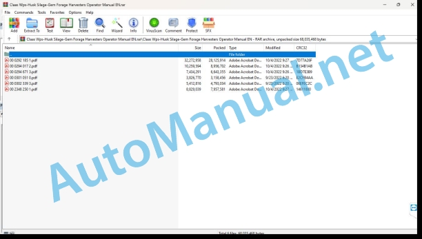
00 0292 185 1.pdf
00 0294 017 2.pdf
00 0294 671 3.pdf
00 0301 051 0.pdf
00 0302 339 3.pdf
00 2348 250 1.pdf
00 0292 185 1.pdf:
DIRECT DISC 610 (Subtype 0310)DIRECT DISC 520 (Subtype 0515)
Table of contents
1 Introduction
1.1 Notes on the manual
1.1.1 Validity of the manual
1.1.2 Information about this Operator’s Manual
1.1.3 Symbols and notices
1.1.4 Optional equipment
1.1.5 Qualified specialist workshop
1.1.6 Notes on maintenance
1.1.7 Notes on warranty
1.1.8 Spare parts and technical questions
1.2 Intended use
1.2.1 Intended use
1.2.2 Reasonably foreseeable misuse
2 Safety
2.1 Identifying warnings
2.1.1 Hazard signs
2.1.2 Signal word
2.2 Safety rules
2.2.1 Importance of Operator’s Manual
2.2.2 Observing safety decals and warnings
2.2.3 Requirements for all persons working with the machine
2.2.4 Children in danger
2.2.5 Hazard areas
2.2.6 Standing between the machine and the front attachment
2.2.7 Hitching of machine with front attachment or transport trailer
2.2.8 Danger of injury from rotating shafts
2.2.9 Structural changes
2.2.10 Optional equipment and spare parts
2.2.11 Control of the machine while it is running
2.2.12 Only use once properly put into operation
2.2.13 Technical condition
2.2.14 Danger due to damage to the machine
2.2.15 Complying with technical limit values
2.2.16 Danger from machine parts running on
2.2.17 Keeping protective equipment functional
2.2.18 Personal protective equipment
2.2.19 Wearing suitable clothing
2.2.20 Removing dirt and loose objects
2.2.21 Preparing the machine for road travel
2.2.22 Hazards when driving on the road and on the field
2.2.23 Parking the machine securely
2.2.24 Unsuitable operating materials
2.2.25 Safe handling of operating and auxiliary materials
2.2.26 Environmental protection and disposal
2.2.27 Fire hazard
2.2.28 Electrocution from electrical system
2.2.29 Liquids under pressure
2.2.30 Hot surfaces
2.2.31 Only carry out work on the machine when it is shut down
2.2.32 Maintenance operations and repair work
2.2.33 Lifted machine parts and loads
2.2.34 Danger from welding work
2.3 Safety marking
2.3.1 Layout of safety decals
2.3.2 Safety decals on the machine
3 Machine description
3.1 Overview and method of operation
3.1.1 Machine overview
3.1.2 Overview of the gearbox
3.1.3 Overview of the cutting disc direction of rotation
3.1.4 Function of machine
3.2 Optional equipment
3.2.1 Hydraulic paddle roller adjustment*
3.2.2 Transport heads*
3.2.3 High-cut skids*
3.2.4 Wear skids*
3.2.5 Wheel chocks
3.2.6 Support brackets*
3.3 Identification plates and identification number
3.3.1 Machine identification plate
3.4 Information on the machine
3.4.1 Stickers on the machine
4 Operating and control elements
4.1 Fitting frame
4.1.1 Locking device
5 Technical specifications
5.1 DIRECT DISC 610
5.1.1 Approved machines
5.1.2 Dimensions
5.1.3 Weight
5.1.4 Version
5.1.5 Lubricants
5.2 DIRECT DISC 520
5.2.1 Approved machines
5.2.2 Dimensions
5.2.3 Weight
5.2.4 Version
5.2.5 Lubricants
6 Machine preparation
6.1 Switching off and securing the machine
6.1.1 Switching off and securing machine
6.1.2 Secure the front attachment when raised
6.2 Accessing workplaces and maintenance places
6.2.1 Opening and closing maintenance flaps
Opening left and right maintenance flaps
Closing left and right maintenance flaps
Opening centre maintenance flap
Closing centre maintenance flap
6.2.2 Opening and closing bonnet
Opening bonnet
Closing bonnet
6.3 Adapting the forage harvester
6.3.1 Fitting the mower head starting clutch hydraulic connection*
6.3.2 Adjust the front attachment CEBIS
6.4 Assembling the front attachment
6.4.1 Overview of shipping package
6.4.2 Mounting cutterbar skids
6.5 Mounting front attachment
6.5.1 Opening the locking device
6.5.2 Lubricating clutch flange
6.5.3 Fitting the front attachment
6.5.4 Closing the locking device
6.5.5 Attaching front attachment using support shoes
6.5.6 Attaching front attachment with support shoes*
6.5.7 Connecting the hydraulic hose lines
6.5.8 Connecting the power supply
6.5.9 Unlocking the pendulum frame
6.6 Adjusting the front attachment
6.6.1 Adjusting the locking device
6.6.2 Adjusting the locking linkage
6.6.3 Check claw coupling
6.6.4 Adjusting the dog clutch
6.7 Removing front attachment
6.7.1 Removing the front attachment using support shoes
6.7.2 Removing the front attachment with support shoes*
6.7.3 Locking the pendulum frame
6.7.4 Disconnecting the power supply
6.7.5 Disconnecting the hydraulic hoses
6.7.6 Opening the locking device
6.7.7 Unhitching front attachment
6.8 Prepare road travel
6.8.1 Placing the front attachment on the transport trailer
6.9 Preparing fieldwork
6.9.1 Lifting the front attachment off the transport trailer
6.10 Loading the front attachment
6.10.1 Raising the front attachment
7 Operation
7.1 Driving on the road
7.1.1 Driving on public roads
7.2 Fieldwork settings
7.2.1 Adjusting the cutting height
7.2.2 Mower head inclination adjustment
Required parts
Removing wear skids
Removing cutterbar skid
Removing left mower head
Removing right mower head
Setting mower head steeper
Setting mower head flatter
Wheel chocks fitting position
Installing mower head
Install cutterbar skids
Installing wear skids
Adjusting protective strips
7.2.3 Paddle roller adjustment
7.2.4 Adjusting stroke limit
7.2.5 Adjusting the length of cut
7.3 Fieldwork
7.3.1 Using the front attachment
7.3.2 Switching on the front attachment
7.3.3 Raising and lowering the front attachment
7.3.4 Switching on and off the cutting height control
7.3.5 Raising and lowering paddle roller
7.3.6 Reversing the front attachment
7.3.7 Switching off the front attachment
7.3.8 Observe the following during field work
7.3.9 Mowing methods
7.3.10 Instructions for mowing
7.3.11 Difficult conditions of use
7.3.12 Recommendation for environmental protection
8 Faults and remedies
8.1 Overview of problems
8.1.1 Overview of problems on the machine
8.2 Electrical and electronic system
8.2.1 Adjusting the speed sensor
9 Maintenance
9.1 Service interval overview
9.1.1 Before the harvest
9.1.2 After the first 50 operating hours
9.1.3 Every 8 operating hours
9.1.4 Every 50 operating hours
9.1.5 Every 250 operating hours
9.1.6 Every 500 operating hours or annually
9.1.7 After the harvest
9.2 Gearbox
9.2.1 Checking the gearbox for leaks
9.2.2 Checking the oil level in the main gearbox
9.2.3 Change the oil in the main gearbox
9.2.4 Checking the oil level in the transfer gearbox
9.2.5 Changing the oil in the transfer gearbox
9.2.6 Checking the angle drive oil level
9.2.7 Changing the angle drive oil
9.2.8 Checking the oil level in the spur gearbox
9.2.9 Changing the spur gearbox oil
9.3 Clutch
9.3.1 Checking the overload clutch
9.3.2 Checking the friction clutch
9.3.3 Venting the friction clutch
9.4 Universal drive shaft
9.4.1 Servicing the universal drive shafts
Universal drive shafts overview
Removing/fitting universal drive shaft guard
9.5 Drives
9.5.1 Checking the drive chain
9.5.2 Checking the paddle roller drive chain
9.5.3 Checking intake auger spring tension
9.6 Hydraulic system
9.6.1 Checking the hydraulic hoses
9.7 Mower unit
9.7.1 Checking the oil level in the mower heads
Checking the oil level in the left mower head
Checking the oil level in the right mower head
9.7.2 Changing the mower head oil
Draining the oil in the left mower head
Topping up the oil in the left mower head
Draining the oil in the right mower head
Topping up the oil in the right mower head
9.7.3 Checking the oil level in the mower heads
Checking mower head oil levels
9.7.4 Changing the mower head oil
Draining mower head oil
Topping up mower head oil
9.7.5 Check the mower knives
9.7.6 Replacing the mower knives
9.7.7 Check the cutting discs
9.7.8 Checking the mower knife holder
9.7.9 Replacing the cutting discs
9.7.10 Checking transport drums
9.7.11 Replacing feed cylinders
9.7.12 Adjusting the anti-wrap guard
9.8 Assembly parts and bodywork
9.8.1 Clean the machine
9.8.2 Preserve the machine
9.8.3 Checking the fittings
9.9 Lubrication plan
9.9.1 Lubricate lubrication points every 50 operating hours
9.9.2 Lubricate lubrication points every 250 operating hours
10 Placing out of operation and disposal
10.1 General information
10.1.1 Placing out of operation and disposal
11 EC declaration of conformity
11.1 DIRECT DISC 610
11.1.1 EC Declaration of Conformity
11.2 DIRECT DISC 520
11.2.1 EC Declaration of Conformity
12 Technical terms and abbreviations
12.1 Terms and explanations
12.1.1 Technical terms
12.1.2 Abbreviations
00 0294 017 2.pdf:
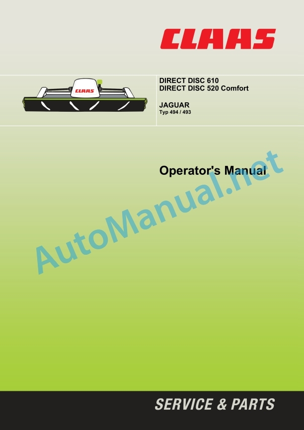
1 Introduction
Introduction
Validity
2 Contents
3 Preface
Of special importance
Identification plate
Transport on public roads
Safety device for driving on public roads
4 Safety rules
IIntended use
Reasonable foreseeable misuse
Identification of warnings and hazard signs
General safety and accident prevention regulations
Decommissioning and disposal
Safety decals with pictorials
Safety support
5 Specifications
DIRECT DISC 610
DIRECT DISC 520 Comfort
6 Assembly
Loading and unloading the front attachment
Fitting the front attachment for the first time
Front attachment
Installing cutterbar skids
Attaching / removing prop stands
Using the front attachment
Adjusting the front attachment
Operating the front attachment on the JAGUAR Type 494
Operation of the front attachment on the JAGUAR Type 493
Adjustments on forage harvester
Additional weights
JAGUAR Type 493
Boosted drive feeder unit
Shipping package installation kit JAGUAR Type 493 (D03/0090)
Installing the 3-groove belt drive
Additional damping
Setting the drop rate (JAGUAR Type 493 only)
JAGUAR Type 494
Boosted drive feeder unit
Shipping package installation kit JAGUAR Type 494 (D03/0090)
CEBIS settings
Front attachment menu
7 Prior to operation
Check and observe the following before putting into operation
Fitting front attachment
Proceed as follows to fit the front attachment:
Opening the lock
Greasing the coupling flange
Hitching up the front attachment
Closing the lock
Connecting hydraulics
Connecting electric system
Checking the setting of the coupling flange to the quick-fit coupling
Setting the paddle roller
Hydraulic adjustment of the paddle roller (additional equipment)
Adjusting cutterbar skids
Setting mower head inclination
Required parts
Setting the mower head to a steeper angle
Setting inclination of mower head to a smaller angle
Setting the safety bars
Working and transport position
Transport position
Working position
Removing and storing the front attachment
8 Operation
Operation
Precondition
Multifunction handle
Raising and lowering the front attachment
Operating front attachment
Instructions for mowing
Difficult application conditions
Adjusting cutting height
Locking / unlocking the pendulum frame
Adjusting length of cut
Length and height of cut range
Additional equipment
Hydraulic adjustment of the paddle rollers (R03/0100)
Laser pilot (R03/0090, DIRECT DISC 520 Comfort only)
Feed hats (D03/0080)
Additional damping (R05/0060, JAGUAR Type 493 only)
3-groove belt drive (D03/0090)
Speed sensor
9 Maintenance
Important maintenance instructions
Hydraulic system
Lubrication
Safety devices
Drive systems
Intake auger gearbox (A)
Angle drive – mower drive / feeder unit drive (B)
Angle drive – mower drive (C)
Angle drive – mower drive (D)
Breather valve
Mower head
Oil level check
Oil change
Filling capacity:
Clutches
Clutches (E, G)
Torque setting
Friction clutch (E) mower drive
Overload clutch (G) feeder units
Free wheel (F) mower drive
Venting the friction clutch
Lubricating the drive chain
Tensioning steel roller chains
Tensioning drive chain
Tensioning drive chain with clamping bracket
Tensioning drive chain with chain tensioner
Tensioning V-belts
Checking V-belts
Spring adjustment
Spring tension of intakauger
Pendulum frame – adjusting the float springs
Universal drive shafts
Servicg the universal drive shaft
General information on universal drive shafts
Dismantling / fitting universal drive shaft guards
Guard cup, initial gearbox
Guard, universal drive shaft – mower drive / initial gearbox
Universal drive shafts with clamping screws
Mounting lever
Locking the cutting discs
Mower blades
Mower blade box
Checking the mower blades
Quick-change system for mower blades
Checking the mower blade bracket (mower blade quick-change system)
Replacing screwed mower blades
Mower blade fixing (bolted version)
Cutting discs
Checking the cutting discs
Replacing cutting discs
Feed drums
Checking the feed drums
Replacing feed drums
Feed drum cap
Removing / fitting wear bars
Electric system
Setting the speed sensor
Aligning the toothed lock washer
Adjusting spacing speed sensor – toothed lock washer (DIRECT DISC 520 Comfort only)
Hydraulic system
Anti-wrap guard
Setting the anti-wrap guard
Panelling
Side panelling
Top side panelling
Adjusting the lock
Adjusting interlocking bars
Screw connections
Fasteners
Cleaning and care
Winter storage
Lubricants chart
DIRECT DISC 520 Comfort
DIRECT DISC 610
Lubrication points
Malfunctions
10 Lubrication Chart
Safety rules
Lubricants
Lubrication
00 0294 671 3.pdf:
DIRECT DISC transport trailer
Table of contents
Introduction
Notes on the manual
Validity of the manual
Information about this Operator’s Manual
Symbols and notes
Qualified specialist workshop
Notes on maintenance
Notes on warranty
Spare parts and technical questions
Intended use
Intended use
Reasonably foreseeable misuse
Identifying warnings
Hazard signs
Signal word
Safety rules
Meaning of Operator’s Manual
Observing safety decals and warnings
Requirements for all persons working with the machine
Hazard areas
Coupling of machine with front attachment or transport trailer
Structural changes
Optional equipment and spare parts
Technical condition
Keeping the safety devices functional
Personal protective equipment
Wearing suitable clothing
Removing dirt and loose objects
Parking the transport trailer safely
Unsuitable operating materials
Safe handling of operating and auxiliary materials
Environmental protection and disposal
Fire hazard
Maintenance operations and repair work
Safety marking
Layout of safety decals
Safety decals on the transport trailer
Official licence plate
Machine description
Overview and method of operation
Overview of transport trailer
Function of transport trailer
Identification plates and identification numbers
Transport trailer identification plate
Automatic overrun brakes identification plate
Information on the machine
Decal on transport trailer
Operating and display elements
Controls
Retainers
Technical specifications
Transport trailer
Dimensions
Tyres and tyre pressure
Operating utilities
Lubricants
Machine preparation
Unhitching and securing the transport trailer
Unhitching and securing the transport trailer
Assembling the transport trailer
Fitting the orientation aid
Installing the retainers
Fitting the lighting cable
Installing the contact-breaking cable
Adapting the transport trailer
Adapting the retainer to the front attachment
Checking the position of supports
Hitching the transport trailer
Hitching the drawbar
Connecting the lighting
Connecting the contact-breaking cable
Removing the wheel chocks
Releasing the parking brake
Unhitching the transport trailer
Applying the parking brake
Positioning the wheel chock at the wheel
Separating the contact-breaking cable
Disconnecting the lighting
Unhitching the drawbar
Loading the transport trailer
Lifting the transport trailer
Operation
Driving on the road
Driving on public roads
Loading the transport trailer
Placing the front attachment on the transport trailer
Unloading the transport trailer
Lifting the front attachment off the transport trailer
Faults and remedies
Overview of problems
Problems with the transport trailer
Changing the wheel
Maintenance
Service interval overview
Before the harvest
After the first 10 operating hours
After the first 50 operating hours
Every 50 operating hours
Every 250 operating hours
After the harvest
Checking the tyre air pressure
Retightening the wheel nuts
Checking the wheel hub bearing play
Adjusting the wheel hub bearing play
Carrying out a functional check of the brake system
Carrying out a visual inspection of the brake
Checking the adjustment of the wheel brake
Checking the parking brake adjustment
Electrical and electronic system
Checking the lighting
Checking the frame mounting
Assembly parts and bodywork
Checking the wheel chocks
Cleaning the transport trailer
Preserving the transport trailer
Check the fittings
Lubrication plan
Lubricating grease points every 250 operating hours
Putting out of operation and disposal
General information
Removal from service and disposal
EC declaration of conformity
Transport trailer
EC Declaration of Conformity
Technical terms and abbreviations
Terms and explanations
Abbreviations
00 0301 051 0.pdf:
PROFI CAM 3
Table of contents
1 Introduction
1.1 Notes on the manual
1.1.1 Validity of manual
1.1.2 Information about this Operator’s Manual
1.1.3 Symbols and notes
1.1.4 Optional equipment
1.1.5 Qualified specialist workshop
1.1.6 Maintenance information
1.1.7 Warranty notes
1.1.8 Spare parts and technical questions
1.2 Intended use
1.2.1 Intended use
1.2.2 Reasonably foreseeable misuse
2 Safety
2.1 Identifying warnings
2.1.1 Hazard signs
2.1.2 Signal word
2.2 Safety rules
2.2.1 Meaning of Operator’s Manual
2.2.2 Observing safety decals and warnings
2.2.3 Optional equipment and spare parts
3 Product description
3.1 Overview and method of operation
3.1.1 How the PROFI CAM works
3.2 Identification plates and identification number
3.2.1 Position of identification plates
3.2.2 Explanation of PROFI CAM identification plate
3.3 Information on the product
3.3.1 CE marking
4 Operating and control elements
4.1 Camera system
4.1.1 Camera system monitor
4.2 Menu structure
4.2.1 Main menu
4.2.2
4.2.3
4.2.4
4.2.5
4.2.6
5 Technical specifications
5.1 PROFI CAM
5.1.1 Monitor
5.1.2 Camera
5.1.3 Switch box
5.1.4 Degree of protection against foreign bodies and water
6 Preparing the product
6.1 Shutting down and securing the machine
6.1.1 Switching off and securing the machine
6.2 Prior to operation
6.2.1 Carry out prior to operation
6.2.2 Installing the sun protection
6.2.3 Aligning the camera
6.2.4 Connecting the camera electrics
7 Operation
7.1 Monitor
7.1.1 Switching on the monitor
7.1.2 Calling up the menu
7.1.3 Setting a menu item
7.1.4 Setting the image orientation
7.1.5 Setting automatic screen darkening
7.1.6 Image mirroring
7.1.7 Setting the trigger view
7.1.8 Setting the follow-up time for trigger view
7.1.9 Setting the display mode
7.1.10 Activating/deactivating a display mode
8 Faults and remedies
8.1 Electrical and electronic system
8.1.1 Overview of problems on PROFI CAM camera system
8.1.2 Replacing the switch box fuse
9 Maintenance
9.1 Maintenance intervals
9.1.1 Every 10 operating hours or daily
9.2 Camera system
9.2.1 Checking the camera system for dirt
9.2.2 Cleaning the camera
9.2.3 Cleaning the switch box
9.2.4 Cleaning the monitor
10 Placing out of operation and disposal
10.1 General Information
10.1.1 Putting out of operation and disposal
11 Technical terms and abbreviations
11.1 Abbreviations
11.1.1 Units
11.1.2 Abbreviations
11.1.3 Technical terms
00 0302 339 3.pdf:
JAGUAR 990 / 980 / 970 / 960 / 950 / 940 / 930JAGUAR 880 / 870 / 860 / 850 / 840 / 830JAGUAR 990 / 960 TERRA TRAC
Table of contents
1 Introduction
1.1 General information
1.1.1 Validity of manual
1.1.2 Information about this Operator’s Manual
1.1.3 Symbols and notes
1.1.4 Maintenance notes
1.1.5 Notes on warranty
1.1.6 Spare parts and technical questions
1.2 Identification plates and identification numbers
1.2.1 Identification plate of adapter
2 Safety
2.1 Identifying warnings
2.1.1 Hazard signs
2.1.2 Signal word
2.2 Safety rules
2.2.1 Importance of Operator’s Manual
2.2.2 Observing safety decals and warnings
2.2.3 Requirements made on all persons working with the product
2.2.4 Coupling the machine to the front attachment
2.2.5 Danger of injury on the universal drive shaft
2.2.6 Structural alterations
2.2.7 Technical condition
2.2.8 Unsuitable operating utilities
2.2.9 Environmental protection and disposal
2.2.10 Pressurised fluids
2.3 Safety marking
2.3.1 Structure of safety decals
2.3.2 Safety decals on the adapter
3 Operating and display elements
3.1 Cab and operator’s platform
3.1.1 Controls on B-column
4 Technical specifications
4.1 Adapter
4.1.1 Compatible machines
4.1.2 Dimensions
4.1.3 Weight
4.1.4 Lubricants
5 Operation
5.1 Adapter
5.1.1 Using the adapter
5.1.2 Removing the stripper bars
5.1.3 Adjusting the feed roller speed
5.1.4 Adjusting the cutting height potentiometer
5.1.5 Adjusting the dog clutch
5.1.6 Mounting the adapter
5.1.7 Removing the adapter
6 Maintenance
6.1 Maintenance interval overview
6.1.1 Every 10 operating hours or daily
6.1.2 Every 100 operating hours
6.1.3 Every 500 operating hours or annually
6.2 Lubrication plan
6.2.1 Grease the grease points every 10 operating hours
6.2.2 Grease points, grease every 100 working hours
6.3 Transmission, clutch and driveshaft
6.3.1 Checking the drive gearbox oil level
6.3.2 Changing the drive gearbox oil
Draining the oil
Topping up oil
6.3.3 Checking the output gearbox oil level
6.3.4 Changing the oil of output gearboxes
Draining the oil
Topping up oil
6.3.5 Checking the chain tension
00 2348 250 1.pdf:
DIRECT DISC transport trailer
Table of contents
1 Introduction
1.1 Notes on the manual
1.1.1 Validity of the manual
1.1.2 Information about this Operator’s Manual
1.1.3 Symbols and notes
1.1.4 Qualified specialist workshop
1.1.5 Maintenance notes
1.1.6 Notes on warranty
1.1.7 Spare parts and technical questions
1.2 Intended use
1.2.1 Intended use
1.2.2 Reasonably foreseeable misuse
2 Safety
2.1 Identifying warnings
2.1.1 Hazard signs
2.1.2 Signal word
2.2 Safety rules
2.2.1 Importance of Operator’s Manual
2.2.2 Observing safety decals and warnings
2.2.3 Requirements for all persons working with the machine
2.2.4 Hazard areas
2.2.5 Fitting a front attachment or hitching a transport trailer to the machine
2.2.6 Structural alterations
2.2.7 Optional equipment and spare parts
2.2.8 Technical condition
2.2.9 Keeping safety devices functional
2.2.10 Personal protective equipment
2.2.11 Wearing suitable clothing
2.2.12 Removing dirt and loose objects
2.2.13 Parking the transport trailer safely
2.2.14 Unsuitable operating utilities
2.2.15 Safe handling of operating and auxiliary utilities
2.2.16 Environmental protection and disposal
2.2.17 Avoiding fires
2.2.18 Maintenance operations and repair work
2.3 Safety marking
2.3.1 Structure of safety decals
2.3.2 Safety decals on the transport trailer
2.3.3 Official licence plate
3 Machine description
3.1 Overview and method of operation
3.1.1 Overview of transport trailer
3.1.2 Function of transport trailer
3.2 Identification plates and identification numbers
3.2.1 Transport trailer identification plate
3.2.2 Identification plate of the axles
3.2.3 Automatic overrun brakes identification plate
3.3 Information on the machine
3.3.1 Decal on transport trailer
4 Operating and display elements
4.1 Controls
4.1.1 Retainers
5 Technical specifications
5.1 Transport trailer
5.1.1 Dimensions
5.1.2 Weight
5.1.3 Tyres and tyre pressure
5.2 Operating utilities
5.2.1 Lubricants
6 Machine preparation
6.1 Unhitching and securing the transport trailer
6.1.1 Unhitching and securing the transport trailer
6.2 Assembling the transport trailer
6.2.1 Fitting the orientation aid
6.2.2 Installing the retainers
6.2.3 Fitting the lighting cable
6.2.4 Fitting the chain with the padlock
6.3 Adapting the transport trailer
6.3.1 Adapting the retainer to the front attachment
6.3.2 Checking the position of supports
6.4 Hitching the transport trailer
6.4.1 Removing the chain with the padlock
6.4.2 Hitching the drawbar
6.4.3 Connecting the lighting
6.4.4 Connecting the contact-breaking cable
6.4.5 Removing the wheel chocks
6.4.6 Releasing the parking brake
6.5 Unhitching the transport trailer
6.5.1 Applying the parking brake
6.5.2 Positioning the wheel chock at the wheel
6.5.3 Separating the contact-breaking cable
6.5.4 Disconnecting the lighting
6.5.5 Unhitching the drawbar
6.5.6 Fitting the chain with the padlock
6.6 Prepare road travel
6.6.1 Performing checks prior to road travel
6.7 Loading the transport trailer
6.7.1 Lifting the transport trailer
7 Operation
7.1 Driving on the road
7.1.1 Driving on public roads
7.2 Loading the transport trailer
7.2.1 Placing the front attachment on the transport trailer
7.3 Unloading the transport trailer
7.3.1 Lifting the front attachment off the transport trailer
8 Faults and remedies
8.1 Overview of problems
8.1.1 Problems with the transport trailer
8.2 Chassis
8.2.1 Changing the wheel
9 Maintenance
9.1 Maintenance interval overview
9.1.1 Before the harvest
9.1.2 After the first 10 operating hours
9.1.3 After the first 50 operating hours
9.1.4 Every 50 operating hours
9.1.5 Every 250 operating hours
9.1.6 After the harvest
9.1.7 Every 2 years
9.2 Chassis
9.2.1 Checking the tyre air pressure
9.2.2 Retightening the wheel nuts
9.2.3 Checking the wheel hub bearing play
9.2.4 Adjusting the wheel hub bearing play
9.3 Brake
9.3.1 Carrying out a functional check of the brake system
9.3.2 Carrying out a visual inspection of the brake
9.3.3 Checking the parking brake adjustment
9.4 Electric and electronic system
9.4.1 Checking the lighting
9.5 Frame
9.5.1 Checking the frame mounting
9.6 Assembly parts and machine body
9.6.1 Checking the wheel chocks
9.6.2 Cleaning the transport trailer
9.6.3 Preserving the transport trailer
9.6.4 Check the fittings
9.7 Lubrication plan
9.7.1 Lubricating grease points every 250 operating hours
10 Putting out of operation and disposal
10.1 General information
10.1.1 Removal from service and disposal
11 EC declaration of conformity
11.1 Transport trailer
11.1.1 UK declaration of conformity
11.1.2 EC Declaration of Conformity
12 Technical terms and abbreviations
12.1 Terms and explanations
12.1.1 Abbreviations
John Deere Repair Technical Manual PDF
John Deere Repair Technical Manual PDF
John Deere Repair Technical Manual PDF
John Deere Diesel Engines POWERTECH 2.9 L Component Technical Manual CTM126 Spanish
John Deere Repair Technical Manual PDF
John Deere Repair Technical Manual PDF
John Deere Transmission Control Unit Component Technical Manual CTM157 15JUL05
John Deere Repair Technical Manual PDF
John Deere Repair Technical Manual PDF
John Deere PowerTech M 10.5 L and 12.5 L Diesel Engines COMPONENT TECHNICAL MANUAL CTM100 10MAY11
John Deere Repair Technical Manual PDF
John Deere Repair Technical Manual PDF
John Deere Repair Technical Manual PDF

