Claas Xerion 5000-4000 (783) Tractors Technical System EN
$150.00
- Model: Xerion 5000-4000 (783) Tractors
- Type Of Manual: Technical System
- Language: EN
- Format: PDF(s)
- Size: 236 MB
File List:
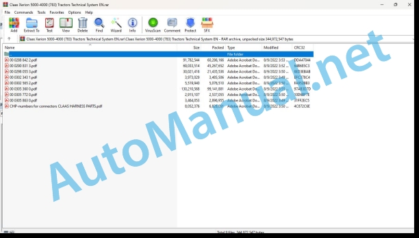
00 0288 842 2.pdf
00 0290 831 3.pdf
00 0298 055 3.pdf
00 0302 343 1.pdf
00 0302 565 2.pdf
00 0305 360 0.pdf
00 0305 772 0.pdf
00 0305 863 0.pdf
CHP-numbers for connectors CLAAS HARNESS PARTS.pdf
00 0288 842 2.pdf:
XERION 5000 TRAC / TRAC VCXERION 4500 TRAC / TRAC VCXERION 4000 TRAC / TRAC VCXERION 4000 SADDLE TRAC
Table of contents
Introduction
Safety rules
Safety and hazard information
Validity of manual
Overview
CCN explanation
CCN (CLAAS Component Number)
Electric system standard
Overview
Hydraulic system standard
Overview
CCN (CLAAS Component Number)
01 Engine
0135 Cooling system
Engine cooling (fan control and fan reversing)
Measured value tables
Description of function
Fan drive
0150 Engine attachment parts
Starting the diesel engine / 12 Volt and 24 Volt power supply
Description of function
0155 Engine control
Diesel engine monitoring / speed adjustment
0165 Exhaust gas aftertreatment
Exhaust gas treatment
0197 Test/Measurement/Setting
Testing/measuring the fan drive
Measuring the hydraulic fan drive
Return line
Supply line
02 Gearbox / Clutch / Universal drive shaft
0238 Gearbox control
Limp Home
Measured values table
Description of function
0242 Differential
Locking the differentials – ECCOM 4.5
Designation
Measured values table
Description of function
Interaxle differential – sectional drawing
Cross differential – sectional drawing
Locking the differentials – ECCOM 5.0
Measured values table
Description of function
Cross differential – sectional drawing
03 Chassis
0310 Axle
Lift axle
Measured values table
Description of function
Connector pin assignment (B497)
Connector pin assignment (B567)
0325 Driven steering axle, front
Axle 1 (floating axle) lubrication and cooling
Measured values table
Description of function
0330 Driven steering axle, rear
Axle 2 (rigid axle) lubrication and cooling
Measured values table
Description of function
0335 Ground drive
Drive management
Measured values table
Description of function
0365 Tyre pressure control system
Tyre pressure control system
Measured values table
Description of function
0397 Test/Measurement/Setting
Testing/measuring the axle
Axle temperature monitoring
Lubrication pressure monitoring
Checking the lubrication circuit if the lubrication pressure is too low
04 Brake
0405 Service brake
Service brake
Measured values table
Description of function
Service brake hydraulic circuit diagram
Charging the brake accumulator
Description of function
Testing and measurements
Checking the max. brake pressure
0415 Parking brake
Parking brake
Description of function
0420 Trailer air brake
Compressed-air trailer brake system
Key to diagram
Measured values table
Description of function
0425 Trailer hydraulic brake
Hydraulic trailer brake system
Key to diagram
Description of function
05 Steering
0505 Steering
Basic machine steering system
Measured values table
Description of function
Cab in centre position – floating axle steered by Orbitrol steering unit
Key to diagram
Description of function
Cab in rear position – Orbitrol-steered rigid axle
Key to diagram
Description of function
Cab in centre position – Electronic steering (steer by wire)
Key to diagram
Description of function
Emergency steering
Key to diagram
Description of function
0510 Automatic steering
GPS steering system – basic machine with S7/S10 terminal
Measured values table
Measured values table
Description of function
Cab position logics table
GPS steering system – EGNOS/eDif with S7/S10 terminal
Description of function
GPS steering system – Omnistar HP with S7/S10 terminal
Description of function
GPS steering system – RTK with S7/S10 terminal
Description of function
GPS PILOT with RTK
GPS steering system – RTK NET with S7/S10 terminal
Description of function
GPS steering system – BASELINE HD with S7/S10 terminal
Description of function
0597 Testing / measuring / adjusting
Testing/measuring the steering hydraulics
Measuring the pump pressure
Value table
Setting at the volume flow controller (7072)
Testing the orbitrol pressure
Value table
Testing the emergency steering
Value table
Measured values table: oil temperature approx. 50 °C, pressure values in bar
06 Lift device
0605 Rear power lift
Rear power lift – general control / operation
Measured values table
Description of function
Rear power lift control valve module sectional drawing (A115)
Swivel power lift
Measured values tabe
Description of function
0610 Front power lift
Position control / pitching dampening / operation – front power lift
Measured values table
Description of function
08 Drives
0802 Rear PTO
Function of the rear PTO shaft
Description of function
Connector pin assignment B016
Measured values table
Circuit diagram showing rear PTO shaft off – S114 in the centre position
Key to diagram
Description of function
Circuit diagram showing rear PTO shaft ON – via S114
Key to diagram
Description of function
Circuit diagram showing rear PTO shaft running – relays K019 and K020 in self-holding mode
Key to diagram
Description of function
Circuit diagram showing rear PTO shaft EMERGENCY OFF – via U046
Key to diagram
Description of function
Circuit diagram showing rear PTO shaft OFF – VBM reset via S114
Key to diagram
Description of function
Circuit diagram showing rear PTO shaft externally ON – via U048
Key to diagram
Description of function
0809 Hydraulic drive
Auxiliary power take-off – ECCOM 4.5 power hydraulics
Measured values table
Description of function
Additional PTO – Power hydraulics (SaddleTrac)
Measured values table
Description of function
09 Hydraulic system
0910 Pumps
Working hydraulics pump
Steering hydraulics pump
Key to diagram
Emergency steering pump
Key to diagram
Description of function
Cooler pump
Key to diagram
0920 Valves
Steering valve block
Key to diagram
Constant-pressure filter block
Key to diagram
Floating axle lock valve block
Key to diagram
Cab valve block
Key to diagram
Brake pedal valve block
Key to diagram
Three-point braces valve block
Key to diagram
Rear control valves
Key to diagram
Front control valves
Key to diagram
Control valves, general
Key to diagram
Description of function
Description of function
Sectional drawing of control valve
Rear configuration plug (XDTC.1)
Front configuration plug (XDTC.2)
0925 Hydraulic Motors
Cooler motor / reversing valve
Key to diagram
0980 Hydraulic circuit diagram
Overall hydraulics circuit diagram
Overall hydraulic system
Key to diagram
Modules and valve blocks
ECCOM 4.5 transmission hydraulics circuit diagram
ECCOM 4.5 transmission hydraulics
Key to diagram
ECCOM 4.5 transmission hydraulics circuit diagram with heat exchanger
ECCOM 4.5 transmission hydraulics with heat exchanger
Key to diagram
ECCOM 5.0 transmission hydraulics circuit diagram – with rear PTO shaft
ECCOM 5.0 transmission hydraulics with rear PTO shaft
Key to diagram
ECCOM 5.0 transmission hydraulics circuit diagram without rear PTO shaft
ECCOM 5.0 transmission hydraulics without rear PTO shaft
Key to diagram
Rear working hydraulics circuit diagram
Rear working hydraulics without swinging power lift
Key to diagram
Modules and valve blocks
Rear working hydraulics with swinging power lift circuit diagram
Rear working hydraulics with swinging power lift
Key to diagram
Modules and valve blocks
Front working hydraulics circuit diagram
Front working hydraulics
Key to diagram
Modules and valve blocks
Power hydraulics circuit diagram
Power hydraulics
Key to diagram
Lift axle circuit diagram
Lift axle
Key to diagram
Circuit diagram of steering hydraulics with auxiliary steering cylinder
Steering hydraulics with auxiliary steering cylinder
Key to diagram
Valve blocks
Steering hydraulics circuit diagram
Steering hydraulics
Key to diagram
Valve blocks
Fan control circuit diagram
Fan control
Key to diagram
Valve blocks
Hydraulics cooling system circuit diagram
Cooling system
Key to diagram
Valve blocks
Floating axle lock hydraulic system circuit diagram
Lock floating axle
Key to diagram
Valve blocks
Three-point braces hydraulic system circuit diagram
Three-point braces
Key to diagram
Valve blocks
Power hydraulics hydraulic system circuit diagram
Power hydraulics – Trac and Saddle Trac
Key to diagram
Axle lubrication hydraulic system circuit diagram
Axle lubrication
Key to diagram
Trailer brake system circuit diagram
Trailer brake system
Key to diagram
Compressed-air system hydraulic system circuit diagram
Compressed-air system
Key to diagram
Tyre pressure control system compressed air diagram
Tyre pressure control system
Key to diagram
0997 Inspecting / Measuring / Setting
Testing/measuring the floating axle lock
Floating axle lock pressure measurement
Value table
Testing/measuring the working hydraulics
Working hydraulics pressure test
Value table
Value table
Working hydraulics flow rate measurement
Value table
Testing/measuring the auxiliary working hydraulics
Auxiliary working hydraulics pressure test
Value table
Value table
Auxiliary working hydraulics flow rate measurement
Value table
10 Electrical / Electronic equipment
1010 Central electrics
Basic central electrical system
Basic central electrical system (connector)
Roof central electrical system
Signal distribution
1012 Modules / sensors
Overview of modules
Module A004 – DGPS modem (BASELINE HD)
Key to diagram
Key to diagram
Module A004 – DGPS modem (RTK)
Key to diagram
Key to diagram
Module A006 – Automatic air conditioner (ACM)
Key to diagram
Module A007 – Cab fan (CFC)
Assignment
Module A009 – AUTOPILOT (ATP)
Key to diagram
Module A015 – Electronic engine control (ECM) – MTU
Assignment
Module A017 – Engine adaptation (ADM) – Daimler (OM 470, 471, 473LA)
Key to diagram
Module pin assignment
Module A032 – Reduction catalyst (SCR) – Daimler (OM 470, 471, 473LA)
Key to diagram
Module pin assignment
Module A055 – Electro-hydraulic steering 1/2 (ESM)
Key to diagram
Module A055 – Electro-hydraulic steering 2/2 (ESM)
Key to diagram
Module A056 – VDC 1/2 (VDC)
Key to diagram
Module A056 – VDC 2/2 (VDC)
Key to diagram
Module A057 – Transmission control 1/2 (TCU)
Key to diagram
Module A057 – Transmission control 2/2 (TCU)
Key to diagram
Module A058 – Power lift control (EHC)
Key to diagram
Module A060 – Hydraulic control unit (HYD)
Module A064 – Teleservice
Key to diagram
Key to diagram
Module A065 – GPS pilot terminal S7
Key to diagram
Key to diagram
Module A069 – Vehicle base module (VBM)
Module A070 – Power hydraulics (PHM)
Key to diagram
Module A075 – Operating panel (OPM)
Key to diagram
Module A078 – Rear slewing power lift module (SPR)
Key to diagram
Module A085 – Tyre pressure control (TPC)
Module A099 – Advanced control module (ACU)
Module A104 – Worklights (WLP)
Key to diagram
Module A107 – ISO tractor ECU module (ITE)
Module A131 – Cab suspension module (CSP)
Key to diagram
Key to diagram
Module A161 – Advanced control unit 2 (ACU II)
Key to diagram
Module A167 – Position control unit (PCU)
Key to diagram
Module A190 – GPS pilot terminal (ISO) S10
Key to diagram
Key to diagram
1035 Operation / Multifunction control lever
T signal function
Measured values table
Description of function
1080 Electronic circuit diagram
CLAAS Circuit Viewer
Electric circuit diagrams of machine (SCM)
SCM 56 – Earth supply for the central electrical system (roof)
Key to diagram
SCM 60 – Earth supply for the central electrical system (basic)
Key to diagram
SCM 65 – Main power supply
Key to diagram
SCM 70 – Ignition, starting the diesel engine
Key to diagram
SCM 75 – Power supply for modules – Basic equipment I
Key to diagram
SCM 76 – Power supply for modules – Basic equipment II
Key to diagram
SCM 80 – Power supply for modules – Hydraulics I
Key to diagram
SCM 81 – Power supply for modules – Hydraulics II
Key to diagram
SCM 85 – Power supply for modules – Engine
Key to diagram
SCM 90 – Power supply for modules – Variants
Key to diagram
SCM 95 – T signal
SCM 100 – CAN 0 (vehicle CAN) – 1/2
Key to diagram
SCM 101 – CAN 0 (vehicle CAN) – 2/2
SCM 105 – CAN 1 (J1939 CAN)
Key to diagram
SCM 110 – CAN 3 (steering CAN)
SCM 115a – CAN 4 (hydraulics CAN) – with rear power lift
SCM 115b – CAN 4 (hydraulics CAN) – without rear power lift
SCM 120 – CAN 4 (hydraulics CAN) – 2/2
Key to diagram
SCM 125 – CAN 5 (ISO CAN)
Key to diagram
SCM 130 – CAN 7 (config. CAN)
Key to diagram
SCM 135 – CAN 8 (OEM engine CAN)
Key to diagram
SCM 140 – Diesel engine monitoring/fan speed adjustment
Key to diagram
SCM 145 – Urea injection
Key to diagram
SCM 150 – Machine monitoring
Key to diagram
SCM 155 – Road travel circuit
Key to diagram
SCM 160 – Brake system
Key to diagram
SCM 165 – Main lighting circuit, side light, back-up light
Key to diagram
SCM 170 – Full beam, drive light changeover I
Key to diagram
SCM 171 – Dipped beam, drive light changeover II
Key to diagram
SCM 175 – Work lights I
Key to diagram
SCM 180 – Work lights II
Key to diagram
SCM 185 – Warning beacon
Key to diagram
SCM 190 – Turn signal indicator system
Key to diagram
SCM 195 – Instrument lighting
Key to diagram
SCM 200 – Cab rotation, cab position detection
Key to diagram
SCM 205 – Cab suspension
Key to diagram
SCM 210 – Mirror adjustment
Key to diagram
SCM 215 – Components fitted in the cab
Key to diagram
SCM 216 – Horn, air horn
Key to diagram
SCM 220 – Automatic air conditioner
Key to diagram
SCM 225 – Windscreen wiper, windscreen washer
Key to diagram
SCM 230 – Rear power lift control
Key to diagram
SCM 235 – Auxiliary heater
Key to diagram
SCM 240 – External operating elements (working hydraulics)
Key to diagram
SCM 245 – Internal operating elements (working hydraulics)
Key to diagram
SCM 250 – Teleservice
Key to diagram
SCM 255 – GPS pilot S7/S10
Key to diagram
SCM 260 – ProfiCam
Key to diagram
SCM 265 – Service sockets, diagnostic plug
Key to diagram
SCM 270 – ISO sockets
Key to diagram
SCM 275 – 24 V ABS trailer socket
Key to diagram
SCM 280 – XXL axle
Key to diagram
SCM 281 – Lift axle
Key to diagram
SCM 285a – Locking differentials – ECCOM 4.5
Key to diagram
SCM 285b – Locking differentials – ECCOM 5.0
Key to diagram
SCM 290 – Locking the floating axle
Key to diagram
SCM 295 – Drive management
Key to diagram
SCM 300 – Steering
Key to diagram
SCM 305 – Transmission control, Limp Home
Key to diagram
SCM 310 – Rear PTO shaft circuit
Key to diagram
SCM 315 – Additional PTO, power hydraulics
Key to diagram
SCM 325 – Front power lift control
Key to diagram
SCM 330 – Rear swinging power lift
Key to diagram
SCM 335 – Three-point braces
Key to diagram
SCM 340 – Central lubrication system
Key to diagram
SCM 345 – Tyre pressure control system
Key to diagram
SCM 350 – Spare
Key to diagram
SCM 355 – Overview of modules I
Key to diagram
SCM 360 – Overview of modules II
Key to diagram
SCM 375 – Overview of connectors
1081 Overview of Connectors
Connector database (chp CLAAS)
12 Cab / Operator’s platform
1205 Cab suspension
Cab suspension
Measured values table
Sectional view of spring/damper element and proportional valve
Description of function
1210 Cab
Rotating / raising / lowering / locking the cab
Rotating / raising / lowering / locking the cab function overview
Measured values table
Description of function
1230 Seat
Seat contact
Description of function
1240 Air condition
Automatic air conditioner
Measured values table
Description of function
Test menu:
Test menu operation
1297 Inspecting / Measuring / Setting
Testing/measuring the cab
Lift tower pressure measurement
92 Diagnosis
9210 Error codes machine
FMI (Failure Mode Indicator)
FMI 00 (Signal too high)
FMI 01 (Signal too low)
FMI 02 (Erratic signal)
FMI 03 (Voltage too high)
FMI 04 (Voltage too low)
FMI 05 (Current too low)
FMI 06 (Current too high)
FMI 07 (Mechanical failure)
FMI 08 (Abnormal frequency signal)
FMI 09 (Communication error)
FMI 10 (Rate of signal change too fast)
FMI 11 (multiple faults)
FMI 12 (ECU defective)
FMI 13 (Signal outside of calibration range)
FMI 16 (Parameter not available)
FMI 17 (ECU not responding)
FMI 18 (Power supply failure)
FMI 19 (Software conditions not met)
FMI 95 (no signal change)
FMI 96 (CAN Bus system defective)
FMI 97 (Erratic condition)
FMI 98 (Warning)
FMI 99 (Info)
Machine fault code list (DTC)
DTC (Diagnostic Trouble Code) overview
Position of components
Hydraulic system
1000 Oil reservoir / oil filter / oil cooler
2000 Pump / motor
3000 Hydraulic cylinders
4000 Restrictor / orifice plate
5000 Accumulator
6000 Valves – mechanically actuated
7000 Valves – hydraulically actuated
8000 Couplings / connections
9000 Measuring points / gauges
Electric system
A Terminal / modules
B Sensors
C Electrical/electronic devices
E Lighting
G Voltage sources
H Signal system / signal light
M Motor (electric)
R Potentiometer / resistor
S Switch / pushbutton – Cab operation
U Switch – external operation
V Electronic component
X Connectors
Y Solenoid coils
Z Actual value switch
00 0290 831 3.pdf:
XERION 5000 TRAC / TRAC VCXERION 4500 TRAC / TRAC VCXERION 4000 TRAC / TRAC VC
Table of contents
Introduction
Safety rules
Safety and hazard information
Validity of manual
Overview
CCN explanation
CCN (CLAAS Component Number)
Electric systems standard
Overview
Hydraulic system standard
Overview
CCN (CLAAS Component Number)
01 Engine
0135 Cooling system
Engine cooling (fan control and fan reversing)
Measured value tables
Description of function
Fan drive
0150 Engine attachment parts
Starting the diesel engine / 12 Volt and 24 Volt power supply
Description of function
0155 Engine control
Diesel engine monitoring / speed adjustment
0165 Exhaust gas aftertreatment
Exhaust gas treatment
02 Gearbox / Clutch / Universal drive shaft
0238 Gearbox control
Limp Home
Measured values table
Description of function
0242 Differential
Locking the differentials – ECCOM 4.5
Designation
Measured values table
Description of function
Interaxle differential – sectional drawing
Cross differential – sectional drawing
Locking the differentials – ECCOM 5.0
Measured values table
Description of function
Cross differential – sectional drawing
03 Chassis
0325 Driven steering axle, front
Axle 1 (floating axle) lubrication and cooling
Measured values table
Description of function
Axle temperature monitoring
Lubrication pressure monitoring
0330 Driven steering axle, rear
Axle 2 (rigid axle) lubrication and cooling
Measured values table
Description of function
Axle temperature monitoring
Lubrication pressure monitoring
0335 Ground drive
Drive management
Measured values table
Description of function
0365 Tyre pressure control system
Tyre pressure control system
Measured values table
Description of function
04 Brake
0405 Service brake
Service brake
Measured values table
Description of function
Service brake hydraulic circuit diagram
Charging the brake accumulator
Description of function
Testing and measurements
Checking the max. brake pressure
0415 Parking brake
Parking brake
Description of function
0420 Trailer air brake
Compressed-air trailer brake system
Key to diagram
Measured values table
Description of function
0425 Trailer hydraulic brake
Hydraulic trailer brake system
Key to diagram
Description of function
05 Steering
0505 Steering
Cab in centre position – floating axle steered by Orbitrol steering unit
Key to diagram
Description of function
Cab in rear position – Orbitrol-steered rigid axle
Key to diagram
Description of function
Cab in centre position – Electronic steering (steer by wire)
Key to diagram
Description of function
Emergency steering
Key to diagram
Description of function
Testing and measurements
Measured values table: oil temperature approx. 50 °C, pressure values in bar
0510 Automatic steering
Basic machine steering system
Measured values table
Description of function
EGNOS GPS steering system
Description of function
OMNISTAR HP GPS steerig system
Description of function
RTK GPS steering system
Description of function
GPS Pilot with RTK
RTK NET GPS steering system
Description of function
BASELINE HD GPS steering system
Description of function
GPS steering system eDif – extended Differential
Description of function
GPS steering system – basic machine with S7/S10 terminal
Measured values table
Measured values table
Description of function
Cab position logics table
GPS steering system – EGNOS/eDif with S7/S10 terminal
Description of function
GPS steering system – Omnistar HP with S7/S10 terminal
Descriptionof function
GPS steering system – RTK with S7/S10 terminal
Description of function
GPS PILOT with RTK
GPS steering system – RTK NET with S7/S10 terminal
Description of function
GPS steering system – BASELINE HD with S7/S10 terminal
Description of function
06 Lift device
0605 Rear power lift
Rear power lift – general control / operation
Measured values table
Description of function
Rear power lift control valve module sectional drawing (A115)
Swinging power lift
Measured values table
Description of function
0610 Front power lift
Position control / pitching dampening / operation – front power lift
Measured values table
Description of function
08 Drives
0802 Rear PTO
Function of the rear PTO shaft
Description of function
Connector pin assignment B016
Measured values table
Circuit diagram showing rear PTO shaft off – S114 in the centre position
Key to diagram
Description of function
Circuit diagram showing rear PTO shaft ON – via S114
Key to diagram
Description of function
Circuit diagram showing rear PTO shaft running – relays K019 and K020 in self-holding mode
Key to diagram
Description of function
Circuit diagram showing rear PTO shaft EMERGENCY OFF – via U046
Key to diagram
Description of function
Circuit diagram showing rear PTO shaft OFF – VBM reset via S114
Key to diagram
Description of function
Circuit diagram showing rear PTO shaft externally ON – via U048
Key to diagram
Description of function
0809 Hydraulic drive
Auxiliary power take-off – ECCOM 4.5 power hydraulics
Measured values table
Description of function
Additional PTO – Power hydraulics (SaddleTrac)
Measured values table
Description of function
09 Hydraulic system
0910 Pumps
Working hydraulics pump
Steering hydraulics pump
Key to diagram
Emergency steering pump
Key to diagram
Description of function
Cooler pump
Key to diagram
0920 Valves
Steering valve block
Key to diagram
Constant-pressure filter block
Key to diagram
Floating axle lock valve block
Key to diagram
Cab valve block
Key to diagram
Brake pedal valve block
Key to diagram
Three-point braces valve block
Key to diagram
Rear control valves
Key to diagram
Front control valves
Key to diagram
Control valves, general
Key to diagram
Description of function
Description of function
Sectional drawing of control valve
Rear configuration plug (XDTC.1)
Front configuration plug (XDTC.2)
0925 Hydraulic Motors
Cooler motor / reversing valve
Key to diagram
0980 Hydraulic circuit diagram
Overall hydraulics circuit diagram
Overall hydraulic system
Key to diagram
Modules and valve blocks
ECCOM 4.5 transmission hydraulics circuit diagram
ECCOM 4.5 transmission hydraulics
Key to diagram
ECCOM 4.5 transmission hydraulics circuit diagram with heat exchanger
ECCOM 4.5 transmission hydraulics with heat exchanger
Key to diagram
ECCOM 5.0 transmission hydraulics circuit diagram – with rear PTO shaft
ECCOM 5.0 transmission hydraulics with rear PTO shaft
Key to diagram
ECCOM 5.0 transmission hydraulics circuit diagram without rear PTO shaft
ECCOM 5.0 transmission hydraulics without rear PTO shaft
Key to diagram
Rear working hydraulics circuit diagram
Rear working hydraulics without swinging power lift
Key to diagram
Modules and valve blocks
Rear working hydraulics with swinging power lift circuit diagram
Rear working hydraulics with swinging power lift
Key to diagram
Modules and valve blocks
Front working hydraulics circuit diagram
Front working hydraulics
Key to diagram
Modules and valve blocks
Circuit diagram of steering hydraulics with auxiliary steering cylinder
Steering hydraulics with auxiliary steering cylinder
Key to diagram
Valve blocks
Steering hydraulics circuit diagram
Steering hydraulics
Key to diagram
Valve blocks
Fan control circuit diagram
Fan control
Key to diagram
Valve blocks
Hydraulics cooling system circuit diagram
Cooling system
Key to diagram
Valve blocks
Floating axle lock hydraulic system circuit diagram
Lock floating axle
Key to diagram
Valve blocks
Three-point braces hydraulic system circuit diagram
Three-point braces
Key to diagram
Valve blocks
Power hydraulics hydraulic system circuit diagram
Power hydraulics – Trac and Saddle Trac
Key to diagram
Axle lubrication hydraulic system circuit diagram
Axle lubrication
Key to diagram
Trailer brake system circuit diagram
Trailer brake system
Key to diagram
Compressed-air system hydraulic system circuit diagram
Compressed-air system
Key to diagram
Tyre pressure control system compressed air diagram
Tyre pressure control system
Key to diagram
10 Electrical / Electronic equipment
1010 Central electrics
Basic central terminal compartment
Basic central terminal compartment decal
1012 Modules / sensors
Overview of modules
Module A004 – DGPS modem (RTK)
Key to diagram
Key to diagram
Module A006 – Automatic air conditioner (ACM)
Key to diagram
Module A007 – Cab fan (CFC)
Assignment
Module A009 – AUTOPILOT (ATP)
Key to diagram
Module A015 – Electronic engine control (ECM) – MTU
Assignment
Module A017 – Engine adaptation (ADM) – Daimler (OM 470, 471, 473LA)
Key to diagram
Module pin assignment
Module A032 – Reduction catalyst (SCR) – Daimler (OM 470, 471, 473LA)
Key to diagram
Module pin assignment
Module A055 – Electro-hydraulic steering 1/2 (ESM)
Key to diagram
Module A055 – Electro-hydraulic steering 2/2 (ESM)
Key to diagram
Module A056 – VDC 1/2 (VDC)
Key to diagram
Module A056 – VDC 2/2 (VDC)
Key to diagram
Module A057 – Transmission control 1/2 (TCU)
Key to diagram
Module A057 – Transmission control 2/2 (TCU)
Key to diagram
Module A058 – Power lift control (EHC)
Key to diagram
Module A060 – Hydraulic control (HYD)
Module A065 – GPS pilot terminal S7
Key to diagram
Key to diagram
Module A069 – Vehicle base module (VBM)
Module A070 – Power hydraulics (PHM)
Key to diagram
Module A075 – Operating panel (OPM)
Key to diagram
Module A085 – Tyre pressure control (TPC)
Module A099 – Advanced control module (ACU)
Module A104 – Worklights (WLP)
John Deere Repair Technical Manual PDF
John Deere Transmission Control Unit Component Technical Manual CTM157 15JUL05
John Deere Repair Technical Manual PDF
John Deere Repair Technical Manual PDF
John Deere Parts Catalog PDF
John Deere Tractors 7500 Parts Catalog CPCQ26568 30 Jan 02 Portuguese
John Deere Repair Technical Manual PDF
John Deere Repair Technical Manual PDF
John Deere Diesel Engines POWERTECH 2.9 L Component Technical Manual CTM126 Spanish
John Deere Repair Technical Manual PDF
John Deere Repair Technical Manual PDF
John Deere 18-Speed PST Repair Manual Component Technical Manual CTM168 10DEC07
John Deere Repair Technical Manual PDF
John Deere Repair Technical Manual PDF
John Deere Application List Component Technical Manual CTM106819 24AUG20

