Claas Xerion 5000-4500 Trac (E54) Tractors Operator Manual EN
$50.00
- Model: Xerion 5000-4500 Trac (E54) Tractors
- Type Of Manual: Operator Manual
- Language: EN
- Format: PDF(s)
- Size: 338 MB
File List:
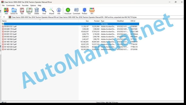
00 0018 552 1.pdf
00 0288 176 0.pdf
00 0291 224 4.pdf
00 0301 051 0.pdf
00 0303 482 0.pdf
00 1169 984 0.pdf
00 1405 164 7.pdf
00 1405 184 7.pdf
00 1420 028 4.pdf
00 1420 056 2.pdf
00 0018 552 1.pdf:
TELEMATICS Website
Table of contents
1 About this Concise Operator’s Manual
1.1 Notes on the manual
1.1.1 Validity of manual
1.1.2 Notes regarding the Concise Operator’s Manual
1.1.3 Notes on warranty
2 Safety
2.1 Intended use
2.1.1 Proper use
3 Product description
3.1 Overview and method of operation
3.1.1 TELEMATICS product variants
3.1.2 TONI (TELEMATICS on implements)
3.1.3 Fleet View
3.1.4 TELEMATICS basic
3.1.5 TELEMATICS advanced
3.1.6 TELEMATICS professional
3.1.7 TELEMATICS app
4 Operating and control elements
4.1 TELEMATICS overview
4.1.1 Illustration conventions of buttons and navigation elements
4.1.2 Symbols and colours
4.2 Menu structure
4.2.1 Start screen
4.2.2 TELEMATICS website site map
4.2.3 Main menu overview
4.2.4
4.2.5
4.2.6
00 0288 176 0.pdf:
XERION 5000 TRAC / TRAC VCXERION 4500 TRAC / TRAC VCXERION 4000 TRAC / TRAC VCXERION 4000 SADDLE TRAC
Table of contents
1 Introduction
1.1 Notes on the manual
1.1.1 Validity of manual
2 Technical specifications
2.1 Operating utilities
2.1.1 Lubricants
00 0291 224 4.pdf:
XERION 5000 TRAC / TRAC VCXERION 4500 TRAC / TRAC VCXERION 4000 TRAC / TRAC VC
Table of contents
1 Introduction
1.1 Notes on the manual
1.1.1 Validity of manual
1.1.2 Information about this Operator’s Manual
1.1.3 Symbols and notes
1.1.4 Optional equipment
1.1.5 Qualified specialist workshop
1.1.6 Notes on maintenance
1.1.7 Notes on warranty
1.1.8 Spare parts and technical questions
1.2 Intended use
1.2.1 Intended use
1.2.2 Reasonably foreseeable misuse
2 Safety
2.1 Identifying warnings
2.1.1 Hazard signs
2.1.2 Signal word
2.2 Safety rules
2.2.1 Importance of the Operator’s Manual
2.2.2 Observing safety decals and warnings
2.2.3 Requirements made on all persons working with the tractor
2.2.4 Children in danger
2.2.5 Hazard areas
2.2.6 Staying between the tractor and the machine
2.2.7 Persons riding on the machine
2.2.8 Hitching an implement or trailer to the tractor
2.2.9 Risk of injury on the PTO shaft
2.2.10 Danger of injury on the universal drive shaft
2.2.11 Do not attach a frontloader
2.2.12 Structural changes
2.2.13 Optional equipment and spare parts
2.2.14 Forestry work
2.2.15 Controlling the tractor when it is running
2.2.16 Operation only following proper putting into operation
2.2.17 Technical condition
2.2.18 Danger from damage on the tractor
2.2.19 Respecting technical limit values
2.2.20 Danger from machine parts running on
2.2.21 Keeping the safety devices functional
2.2.22 Personal protective equipment
2.2.23 Wearing suitable clothing
2.2.24 Removing dirt and loose objects
2.2.25 Preparing the tractor for road travel
2.2.26 Hazards when driving on the road and on the field
2.2.27 Parking the tractor securely
2.2.28 Unsuitable operating materials
2.2.29 Safe handling of operating and auxiliary materials
2.2.30 Fuel is hazardous to your health
2.2.31 Refrigerant is hazardous to your health
2.2.32 Environmental protection and disposal
2.2.33 Keep the cab free of chemicals
2.2.34 Handling of crop protection agents and fertilisers
2.2.35 Fire hazard
2.2.36 Lethal electrocution from overhead lines
2.2.37 Behaviour in case of voltage flash-over from overhead lines and when lightning strikes
2.2.38 Electrocution by electric system
2.2.39 Vibrations may cause health problems
2.2.40 Liquids under pressure
2.2.41 Compressed air
2.2.42 Toxic exhaust gas
2.2.43 Hot surfaces
2.2.44 Accessing and leaving the machine safely
2.2.45 Working on the tractor only when shut down
2.2.46 Maintenance operations and repair work
2.2.47 Raised tractor parts and loads
2.2.48 Hazard posed by welding work
2.2.49 Checking and charging the battery
2.3 Safety marking
2.3.1 Layout of safety decals
2.3.2 Engine
2.3.3 Brake
2.3.4 Power lift
2.3.5 Drives
2.3.6 Electric system
2.3.7 Cab and operator’s platform
2.3.8 Attachment parts and housing
3 Tractor description
3.1 Overview and method of operation
3.1.1 Overview, front and left
3.1.2 Overview, rear and right
3.1.3 Diesel engine overview
3.1.4 Rear power lift overview
3.1.5 Front power lift overview
3.1.6 Overview of drive lights
3.1.7 Overview of work lights
3.2 Optional equipment
3.2.1 Tyre pressure control system*
3.2.2 Power hydraulics*
3.2.3 PROFI CAM*
3.3 Identification plates and identification numbers
3.3.1 Diesel engine identification plate
3.3.2 Transmission identification plate
3.3.3 Axles identification plate
3.3.4 Identification plates of hitches
3.3.5 Identification plate of cab
3.3.6 Identification plate of driver’s seat
3.3.7 Identification plate of tractor
3.4 Information on the tractor
3.4.1 Marking of tyres
3.4.2 Decal on the tractor
4 Operating and display elements
4.1 Cab and operator’s platform
4.1.1 Switch console
4.1.2 Tractor control panel
4.1.3 Multifunction handle
4.1.4 Cab roof
4.1.5 Lighting control panel
4.1.6 Air conditioner control panel
4.1.7 B-pillar controls
4.1.8 Ignition lock
4.1.9 Steering column
4.1.10 Vehicle information unit
4.1.11 Driver’s seat
4.1.12 Camera system monitor
4.2 Exterior operator panel
4.2.1 Front external operation
4.2.2 Rear external operation
4.3 Sockets
4.3.1 Front sockets
4.3.2 Rear sockets
4.3.3 Diesel engine diagnosis socket
4.4 CEBIS on-board computer
4.4.1 On-board information system control panel
4.4.2 Vehicle control display
4.4.3 Working display
4.4.4 Fault display
4.4.5 Status symbols
Transmission
Chassis and brakes
Steering
Hydraulic system and electric system
Cab and maintenance
CLAAS SEQUENCE MANAGEMENT
4.4.6 Main menu
4.4.7
4.4.8
4.4.9
4.4.10
4.4.11
4.4.12
4.4.13
4.5 Power hydraulics
4.5.1 Monitor overview
4.5.2 Function display
4.5.3 Status display
5 Technical specifications
5.1 XERION
5.1.1 Dimensions
5.1.2 Width
5.1.3 Weight
5.1.4 Permitted weight
5.1.5 Load rating of tyres
5.1.6 Tyre inflation pressure
5.1.7 Diesel engine
5.1.8 Transmission and axles
5.1.9 Brake
5.1.10 Compressed-air brake system
Dual-circuit air brake
5.1.11 Rear power lift
5.1.12 Front power lift
5.1.13 Hitch
Automatic hitch
Maximum tongue load
5.1.14 Towing hitch
5.1.15 Rear PTO shaft
5.1.16 Hydraulic system
5.1.17 Power hydraulics*
5.1.18 Hydraulic ports
Additional control units
Power Beyond ports*
5.1.19 Electric system
5.1.20 Noise level
5.1.21 Vibration intensity
5.1.22 Protection level of cab
5.2 Operating utilities
5.2.1 Lubricants
5.2.2 Hydraulic oil
5.2.3 Coolant
5.2.4 Fuel
5.2.5 Permitted fuels
6 Tractor preparation
6.1 Securing the tractor
6.1.1 Switching off and securing the tractor
6.1.2 Securing the tractor
6.1.3 Loading and lashing down the tractor
6.2 Accessing workplaces and maintenance spaces
6.2.1 Accessing the workplace
6.2.2 Stepping on the access areas
Accessing the
Accessing the
Accessing the
Accessing the
6.3 Prior to putting into operation
6.3.1 Preparing the first putting into operation
6.3.2 Preparing putting the machine into operation
6.3.3 Connecting an implement
6.4 Engine
6.4.1 Selecting a permitted fuel
6.4.2 Observing the fuel specification
6.4.3 Observing the fuel specification
6.4.4 Use of winter fuel at low temperatures
6.4.5 Filling up the tank
Top up fuel
6.5 Gearbox
6.5.1 Use at low outside temperatures
6.6 Chassis
6.6.1 Jacking up the tractor
6.6.2 Relieving the front axle load
6.6.3 Installing the wheels
6.6.4 Removing the wheels
6.6.5 Installing dual fitments
6.6.6 Removing the dual fitments
6.6.7 Installing the steering stops
6.6.8 Setting the floating axle lock
6.6.9 Connecting the tyre pressure control system*
6.6.10 Checking the tyres
6.6.11 Calibrating the pulses / 100 m
6.7 Rear power lift
6.7.1 Fitting an implement
6.7.2 Adjusting the lower links to the float or rigid position
6.7.3 Adjusting the lower link clearance
6.7.4 Adjusting the lift brace length
6.7.5 Installing the upper link on the tractor
6.7.6 Coupling the upper link to the implement
6.7.7 Removing an implement
6.7.8 Calibrating the rear power lift
6.8 Front power lift
6.8.1 Setting the vertical mobility
6.8.2 Fitting an implement
6.8.3 Connecting the upper link
6.8.4 Removing an implement
6.8.5 Adjusting the parking position
6.8.6 Calibrating the front power lift
6.9 Hitch
6.9.1 Adjusting the trailer hitch
6.9.2 Adjusting the swinging drawbar
6.9.3 Fitting an implement
Removing an implement
6.9.4 Fitting an implement
6.9.5 Fitting an implement
Removing an implement
6.9.6 Fitting an implement
Removing an implement
6.9.7 Connecting the trailer to the compressed-air brake system
6.9.8 Connecting the trailer to the hydraulic brake system
6.10 PTO shaft and secondary PTO
6.10.1 Changing the PTO shaft stub
6.10.2 Connecting the universal drive shaft
6.11 Hydraulic system
6.11.1 Connecting the implement to the front hydraulic system
6.11.2 Connecting an implement to the rear hydraulic system
6.11.3 Connecting the implement to a Load Sensing working hydraulics*
6.11.4 Connecting the implement to the power hydraulics
6.12 Electric system
6.12.1 Disconnecting the battery isolating switch
6.12.2 Disconnecting the radar sensor power supply
6.12.3 Adjusting the drive lights
6.12.4 Adjusting the work lights
6.13 Cab and operator’s platform
6.13.1 Rotating the cab
6.13.2 Fitting an additional terminal
6.13.3 Inserting paper into the printer*
6.14 Mud guards
6.14.1 Converting the front mud guards
6.14.2 Converting the rear mud guards
6.15 Ballast and additional weight
6.15.1 Calculating the ballast
Recommended ballast
6.15.2 Checking the ballast
6.15.3 Selecting additional weights*
6.15.4 Installing the additional front weight*
Fitting the basic weight
Fitting the add-on weights
6.15.5 Removing the additional front weight*
Removing the add-on weights
Removing the basic weight
6.15.6 Installing the additional front weight*
Fitting the basic weight
Fitting the add-on weights
6.15.7 Removing the additional front weight*
Removing the add-on weights
Removing the basic weight
6.15.8 Fitting the additional rear weight*
Fitting the base plate
Fitting the add-on weights
6.15.9 Removing the additional rear weight*
Removing the add-on weights
Removing the base plate
6.15.10 Fitting the tool box* to the additional weight
6.16 Legal equipment
6.16.1 Marking excess width
6.16.2 Securing the tractor against rolling away
7 Operation
7.1 Driving and transportation
7.1.1 Preparing road travel
7.1.2 Preparing fieldwork
7.1.3 Driving
Steering
Driving on slopes
7.1.4 Driving with implements
Heavy traction work
7.1.5 Pushing operation
7.1.6 Use with crop protection agents or fertilisers
7.1.7 Starting off against the parking brake
7.1.8 Changing the direction of travel
7.1.9 Activating pitching dampening
Front power lift
Rear power lift
7.1.10 Activating cruise control
7.1.11 Saving the cruise control value
Changing the cruise control value
7.2 CEBIS on-board computer
7.2.1 Switching on CEBIS
7.2.2 Using the
7.2.3 Using the
7.2.4 Setting the area counter
7.2.5 Assigning a function key
7.2.6 Recording a CSM sequence
7.2.7 Playing a CSM sequence
Displaying a sequence
Overriding playing
Interrupting running
7.2.8 Editing a CSM sequence
7.2.9 Assigning the CSM function keys
7.3 Engine
7.3.1 Start the diesel engine
Outside temperature below 0 °C
7.3.2 Stopping the diesel engine
7.3.3 Setting the minimum enginespeed
7.3.4 Saving the fixed engine speed
7.3.5 Activating the fixed enine speed
7.3.6 Changing over the reversing fan
7.4 Gearbox
7.4.1 Shifting the transmission to neutral
7.4.2 Setting the drive range
7.4.3 Setting the driving strategy
7.4.4 Locking the interaxle differential*
7.5 Chassis
7.5.1 Locking the axle differential
7.5.2 Operating the tyre pressure control system*
7.6 Brake
7.6.1 Actuating the foot brake
7.6.2 Parking brake operation
7.6.3 Inching pedal
7.7 Steering
7.7.1 Activating a steering program
Approaching the crab steer mode angle
Changing the crab steer mode direction
Activating the centering aid
7.7.2 Configuring the steering program
7.7.3 Setting the AUTO PILOT*
7.7.4 Activating AUTO PILOT*
7.7.5 Deactivating the AUTO PILOT*
7.7.6 Folding the RTK radio antenna*
7.8 Rear power lift
7.8.1 Operating the rear power lift*
7.8.2 Setting the working position
7.8.3 Setting the transport position
7.8.4 Setting the working mode
7.8.5 Setting tractive force control
7.8.6 Setting the slip control
7.8.7 Adjusting the hydraulic side braces*
Engaging the automatic power lift centring
Setting the lift path up to centring
Setting the centring control time
7.8.8 Operating the hydraulic side braces*
Raising and centring the power lift
Lowering the power lift and setting it to float position
Operating the power lift manually
7.8.9 Deactivating pitching dampening
7.9 Front power lift
7.9.1 Operating the front power lift*
7.9.2 Deactivating pitching dampening
7.10 Hitch
7.10.1 Operating the compressed-air brake
7.10.2 Operating the hydraulic trailer brake
7.11 PTO shaft and secondary PTO
7.11.1 Checking the implement on the PTO shaft
7.11.2 Operating the rear PTO shaft manually
7.11.3 Automatic PTO shaft operation
7.11.4 Engaging the secondary PTO
7.12 Hydraulic system
7.12.1 Unlocking the hydraulic system
7.12.2 Using the hydraulic port
Joystick
White and grey hydraulic port*
Black hydraulic port*
7.12.3 Configuring the hydraulic port
7.13 Power hydraulics
7.13.1 Putting the power hydraulics into operation
7.13.2 Configuring the power hydraulics
7.13.3 Setting the operating mode
7.13.4 Starting the power hydraulics
7.14 Cab and operator’s platform
7.14.1 Opening the emergency exit
Side window
Rear window
7.14.2 Adjusting the cab suspension*
7.14.3 Engaging the seat belt
7.14.4 Adjusting the driver’s seat
Adjusting the arm rest angle
Adjusting the arm rest height
Adjusting the seat depth
Adjusting the seat inclination
Adjusting the seat forward and backward
Extending the back rest
Adjusting the back rest inclination
Engaging the longitudinal horizontal suspension
Engaging the lateral horizontal suspension
Adjusting the seat height and driver’s weight
Adjusting the shock absorption
Switching on the seat heater and seat air conditioner
Adjusting the intervertebral disc support
Rotating the seat
7.14.5 Adjusting the steering column
7.14.6 Adjusting the switch console
7.14.7 Adjusting the rear view mirrors
7.14.8 Adjusting the close proximity mirror
7.14.9 Putting the air conditioner into operation
7.14.10 Switching on the air conditioner
7.14.11 Activating the air conditioner operating mode
Fully automatic mode
Manual ventilation system
ECON mode
REHEAT function
7.14.12 Setting the cab temperature
7.14.13 Adjusting the air conditioner air flow
7.14.14 Displaying the outside temperature
7.14.15 Changing the temperature unit
7.14.16 Activating the afterlight function
7.14.17 Adjusting the sun screen*
7.14.18 Switching on the rear camera*
7.14.19 Switching on the cooling box*
8 Faults and remedies
8.1 CEBIS on-board computer
8.1.1 Displaying fault information
8.1.2 Displaying the alarm list
8.2 Engine
8.2.1 Faults of diesel engine
8.2.2 Overview of diesel engine faults
8.2.3 Calling up engine diagnosis
8.2.4 Shutting down an overheated engine
8.2.5 Draining fuel
8.2.6 Note on electronic engine management
8.3 Transmission and chassis
8.3.1 Limp Home mode
8.3.2 Towing out a stuck tractor
8.3.3 Towing a defective tractor
8.4 Brake
8.4.1 Releasing the parking brake
8.5 Steering
8.5.1 Overview of steering faults
8.6 Power hydraulics
8.6.1 Overview of power hydraulics faults
8.6.2 Displaying diagnosis data
8.7 Electrical and electronic system
8.7.1 Opening the basic central terminal compartment
Swinging the basic central terminal compartment up
8.7.2 Fuses
8.7.3 Relays
8.7.4 Opening the basic central terminal compartment
Swinging the basic central terminal compartment up
8.7.5 Replacing lamps
8.7.6 Assist-starting
8.7.7 Welding work
8.8 Cab and operator’s platform
8.8.1 Overview of air conditioner faults
9 Maintenance
9.1 Maintenance intervals
9.1.1 After the first 50 operating hours
9.1.2 After the first 500 operating hours
9.1.3 Every 10 operating hours or daily
9.1.4 Every 50 operating hours or weekly
9.1.5 Every 100 operating hours
9.1.6 Every 250 operating hours
9.1.7 Every 500 operating hours or annually
9.1.8 Every 1500 operating hours or annually
9.1.9 Every 1500 operating hours
9.1.10 Every 2000 operating hours or every 2 years
9.1.11 Every 3000 operating hours or every 2 years
9.2 Lubrication plan
9.2.1 Greasing the grease points every 10 operating hours
9.2.2 Greasing the grease points every 100 operating hours
9.2.3 Grease points to be greased every 500 h
9.3 Engine housing
9.3.1 Cleaning the venting filter
9.4 Injection and fuel system
9.4.1 Checking the fuel sediment filter for condensate
9.4.2 Replacing the fuel sediment filter
9.4.3 Replacing the fuel filter
9.4.4 Bleed fuel system
9.5 Lubricating oil system
9.5.1 Checking the engine oil level
9.5.2 Draining the engine oil
9.5.3 Changing the engine oil filter
9.5.4 Topping up engine oil
9.6 Cooling system
9.6.1 Checking the drive belt
Checking the drive belt condition
Checking the tension of the drive belt
Removing the drive belt
Installing the drive belt
9.6.2 Checking the coolant level
9.6.3 Checking the coolant anti-freeze protection
9.6.4 Changing the coolant
9.6.5 Topping up coolant
9.6.6 Checking the radiator unit
9.6.7 Checking the cooling air intake screen
9.6.8 Checking the coolant hoses
9.7 Air intake
9.7.1 Checking the air intake
9.7.2 Cleaning the air filter pre-cleaner
9.7.3 Retightening the mounting clamps of the charge air tubes
9.7.4 Removing the air filter main cartridge
9.7.5 Cleaning the air filter main cartridge
9.7.6 Installing the air filter main cartridge
9.7.7 Changing the air filter safety element
9.8 Transmission, clutch and driveshaft
9.8.1 Checking the ground drive transmission oil level
9.8.2 Changing the ground drive transmission oil
Topping up ground drive transmission oil
9.8.3 Changing the ground drive transmission oil filter
9.8.4 Cleaning the ground drive transmission suction filter
9.9 Chassis
9.9.1 Checking the differential oil level
9.9.2 Topping up differential oil
9.9.3 Changing the differential oil
9.9.4 Checking the wheel hub gearbox oil level
9.9.5 Changing the wheel hub gearbox oil
9.9.6 Changing the axle oil filter
9.9.7 Checking the wheel bolts’ tightening torque
9.9.8 Checking the wheel nuts’ tightening torque
9.10 Brake
9.10.1 Compressed air port
9.10.2 Relieving pressure
9.10.3 Checking the function of the compressed-air system drain valve
9.10.4 Having the compressed-air accumulator checked
9.10.5 Changing the compressed-air system air dryer
9.10.6 Cleaning the sinter filter
9.10.7 Checking the parking brake operating clearance
9.11 Hitch
9.11.1 Checking the tow ball wear
9.11.2 Checking the height play of the ball-type hitch
9.11.3 Adjusting the height play of the ball-type hitch
9.12 Drives
9.12.1 Checking the PTO shaft gearbox oil level
9.12.2 Changing the PTO shaft gearbox oil
9.12.3 Topping up PTO shaft gearbox oil
9.12.4 Cleaning the PTO shaft gearbox breather valve
9.13 Hydraulic system
9.13.1 Checking the hydraulic oil level
9.13.2 Changing the hydraulic oil
9.13.3 Replacing the hydraulic system return filter
9.13.4 Changing the hydraulic system pressure filter
9.13.5 Checking the hydraulic system suction filter
9.13.6 Changing the hydraulic system fresh air filter element
9.13.7 Replacing the power hydraulics filter
9.13.8 Checking the leakage oil tank
9.13.9 Checking the hydraulic hoses
9.14 Electrical and electronic system
9.14.1 Replacing the battery
9.15 Cab and operator’s platform
9.15.1 Cleaning and replacing the cab air filter
9.15.2 Cleaning the cab recirculation air filter
9.15.3 Cleaning the units located in the cab roof
9.15.4 Checking the windscreen washer
9.15.5 Checking the air conditioner condenser
9.15.6 Checking the air conditioner filter receiver dryer
9.16 Assembly parts and bodywork
9.16.1 Opening the engine bonnet
9.16.2 Retightening the frame bolts on the front axle
9.16.3 Retightening the frame bolts on the rear axle
9.16.4 Check the fire extinguisher
9.16.5 Cleaning and preserving the tractor
9.16.6 Storing the tractor
10 Putting out of operation and disposal
10.1 General information
10.1.1 Putting out of operation and disposal
11 Technical terms and abbreviations
11.1 Abbreviations
11.1.1 Units
11.1.2 Abbreviations
00 0301 051 0.pdf:
PROFI CAM 3
Table of contents
1 Introduction
1.1 Notes on the manual
1.1.1 Validity of manual
1.1.2 Information about this Operator’s Manual
1.1.3 Symbols and notes
1.1.4 Optional equipment
1.1.5 Qualified specialist workshop
1.1.6 Maintenance information
1.1.7 Warranty notes
1.1.8 Spare parts and technical questions
1.2 Intended use
1.2.1 Intended use
1.2.2 Reasonably foreseeable misuse
2 Safety
2.1 Identifying warnings
2.1.1 Hazard signs
2.1.2 Signal word
2.2 Safety rules
2.2.1 Meaning of Operator’s Manual
2.2.2 Observing safety decals and warnings
2.2.3 Optional equipment and spare parts
3 Product description
3.1 Overview and method of operation
3.1.1 How the PROFI CAM works
3.2 Identification plates and identification number
3.2.1 Position of identification plates
3.2.2 Explanation of PROFI CAM identification plate
3.3 Information on the product
3.3.1 CE marking
4 Operating and control elements
4.1 Camera system
4.1.1 Camera system monitor
4.2 Menu structure
4.2.1 Main menu
4.2.2
4.2.3
4.2.4
4.2.5
4.2.6
5 Technical specifications
5.1 PROFI CAM
5.1.1 Monitor
5.1.2 Camera
5.1.3 Switch box
5.1.4 Degree of protection against foreign bodies and water
6 Preparing the product
6.1 Shutting down and securing the machine
6.1.1 Switching off and securing the machine
6.2 Prior to operation
6.2.1 Carry out prior to operation
6.2.2 Installing the sun protection
6.2.3 Aligning the camera
6.2.4 Connecting the camera electrics
7 Operation
7.1 Monitor
7.1.1 Switching on the monitor
7.1.2 Calling up the menu
7.1.3 Setting a menu item
7.1.4 Setting the image orientation
7.1.5 Setting automatic screen darkening
7.1.6 Image mirroring
7.1.7 Setting the trigger view
7.1.8 Setting the follow-up time for trigger view
7.1.9 Setting the display mode
7.1.10 Activating/deactivating a display mode
8 Faults and remedies
8.1 Electrical and electronic system
8.1.1 Overview of problems on PROFI CAM camera system
8.1.2 Replacing the switch box fuse
9 Maintenance
9.1 Maintenance intervals
9.1.1 Every 10 operating hours or daily
9.2 Camera system
9.2.1 Checking the camera system for dirt
9.2.2 Cleaning the camera
9.2.3 Cleaning the switch box
9.2.4 Cleaning the monitor
10 Placing out of operation and disposal
10.1 General Information
10.1.1 Putting out of operation and disposal
11 Technical terms and abbreviations
11.1 Abbreviations
11.1.1 Units
11.1.2 Abbreviations
11.1.3 Technical terms
00 0303 482 0.pdf:
PROFI CAM 4
Table of contents
1 Introduction
1.1 Notes on the manual
1.1.1 Validity of manual
1.1.2 Information about this Operator’s Manual
1.1.3 Symbols and notes
1.1.4 Optional equipment
1.1.5 Qualified specialist workshop
1.1.6 Maintenance information
1.1.7 Notes on warranty
1.1.8 Spare parts and technical questions
1.2 Intended use
1.2.1 Intended use
1.2.2 Reasonably foreseeable misuse
2 Safety
2.1 Identifying warnings
2.1.1 Hazard signs
2.1.2 Signal word
2.2 Safety rules
2.2.1 Meaning of Operator’s Manual
2.2.2 Structural changes
2.2.3 Optional equipment and spare parts
2.2.4 Operation only following proper putting into operation
2.2.5 Technical status
2.2.6 Respecting technical limit values
Respecting technical limit values
2.2.7 Hazards when driving on roads and fields
3 Product description
3.1 Overview and method of operation
3.1.1 How the PROFI CAM works
3.2 Identification plates and identification number
3.2.1 Identification plates
3.3 Information on the product
3.3.1 CE marking
4 Operating and display elements
4.1 Camera system
4.1.1 Camera system monitor
4.1.2 CEBIS
4.2 Menu structure
4.2.1 Main menu
4.2.2
4.2.3
4.2.4
4.2.5
4.2.6
5 Technical specifications
5.1 PROFI CAM
5.1.1 Monitor
5.1.2 Camera
5.1.3 Switch box
6 Preparing the product
6.1 Switching off and securing the machine
6.1.1 Switching off and securing the machine
6.2 Prior to putting into operation
6.2.1 Carry out prior to operation
6.2.2 Installing the sun protection
6.2.3 Aligning the camera
7 Operation
7.1 Monitor
7.1.1 Switching on the monitor
7.1.2 Calling up the menu
7.1.3 Setting a menu item
7.1.4 Setting the image orientation
7.1.5 Setting automatic screen darkening
7.1.6 Image mirroring
7.1.7 Setting the trigger view
7.1.8 Setting the follow-up time for trigger view
7.1.9 Setting the display mode
7.1.10 Activating/deactivating a display mode
8 Faults and remedies
8.1 Electric and electronic system
8.1.1 Overview of problems on PROFI CAM camera system
9 Maintenance
9.1 Maintenance intervals
9.1.1 Every 10 operating hours or daily
9.2 Camera system
9.2.1 Checking the camera system for dirt
9.2.2 Cleaning the camera
9.2.3 Cleaning the switch box
9.2.4 Cleaning the monitor
10 Putting out of operation and disposal
10.1 General information
10.1.1 Putting out of operation and disposal
11 Technical terms and abbreviations
11.1 Abbreviations
11.1.1 Units
11.1.2 Abbreviations
11.1.3 Technical terms
00 1169 984 0.pdf:
Sensor case for tractors Stage IIIB, IV and VSensor case for tractors Stage IIIB, IV and VSensor case for Stage IIIB, IV and V tractors
Contents
1 Sensorkoffer – Sensor case – Sensor suitcase – Stage IIIB, IV & V
1.1 Auflistung Kofferinhalt
1.1 Listing case content
1.1 Presentation of the contents of the suitcase
00 1405 164 7.pdf:
GPS PILOT
Table of contents
1 Introduction
1.1 General information
1.1.1 Validity of Manual
1.1.2 Information about this Operator’s Manual
1.1.3 Symbols and notes
1.1.4 Optional equipment
1.1.5 Qualified specialist workshop
1.1.6 Maintenance notes
1.1.7 Notes on warranty
1.1.8 Spare parts and technical questions
1.1.9 Licensing for road traffic
Sample report
Clearance certificate
General operating permit
1.2 Intended use
1.2.1 Intended use
1.2.2 Reasonably foreseeable misuse
2 Safety
2.1 Identifying warnings
2.1.1 Hazard signs
2.1.2 Signal word
2.2 Safety rules
2.2.1 Meaning of Operator’s Manual
2.2.2 Update of terminal software
2.2.3 Requirements made on all persons working with the product
2.2.4 Hazard areas
Hazard areas
2.2.5 Interaction between the control terminal and the machine or tractor
2.2.6 Structural changes
2.2.7 Optional equipment and spare parts
2.2.8 Use of USB devices
2.2.9 Operation only following proper putting into operation
2.2.10 Technical status
2.2.11 Hazard from damage on the product
2.2.12 Respecting technical limit values
Respecting technical limit values
2.2.13 Preparing the product for road travel
2.2.14 Hazards when driving on the road with an ISOBUS implement
Switching on the terminal during road travel.
2.2.15 Hazards when driving on the road and on the field
2.2.16 Electrocution by electrical system
2.2.17 Potentially fatal electric shock from overhead lines
2.2.18 Liquids under pressure
2.2.19 Maintenance operations and repair work
2.2.20 Driving with the GPS PILOT
Road travel
Fieldwork
2.2.21 Working with Task Control* and Section Control*
3 Product description
3.1 Overview and method of operation
3.1.1 Overview of GPS PILOT – Hydraulic system
3.1.2 Over
John Deere Repair Technical Manual PDF
John Deere Repair Technical Manual PDF
John Deere DF Series 150 and 250 Transmissions (ANALOG) Component Technical Manual CTM147 05JUN98
John Deere Repair Technical Manual PDF
John Deere Repair Technical Manual PDF
John Deere 16, 18, 20 and 24HP Onan Engines Component Technical Manual CTM2 (19APR90)
John Deere Repair Technical Manual PDF
John Deere Repair Technical Manual PDF
John Deere Repair Technical Manual PDF
John Deere Diesel Engines PowerTech 4.5L and 6.8L – Motor Base Technical Manual 07MAY08 Portuguese
John Deere Repair Technical Manual PDF
John Deere Repair Technical Manual PDF

