Claas Xerion 5000-4500 Trac (E54) Tractors Technical System EN
$150.00
- Model: Xerion 5000-4500 Trac (E54) Tractors
- Type Of Manual: Technical System
- Language: EN
- Format: PDF(s)
- Size: 113 MB
File List:
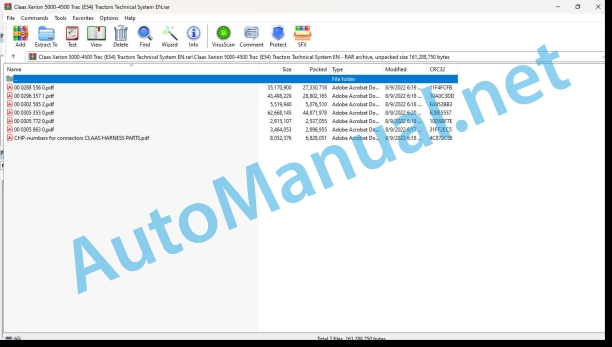
00 0288 556 0.pdf
00 0296 357 1.pdf
00 0302 565 2.pdf
00 0305 355 0.pdf
00 0305 772 0.pdf
00 0305 863 0.pdf
CHP-numbers for connectors CLAAS HARNESS PARTS.pdf
00 0288 556 0.pdf:
PERKINS 2206D – E13 TA
Table of contents
CCN explanation
CCN (CLAAS Component Number)
Electric system standard
Overview
CCN (CLAAS Component Number)
Introduction
Validity of manual
Validity of manual
Safety rules
Safety and hazard information
General information
Important!
Hazard signs
Signal word
Regulations for avoiding accidents with personal injuries
Testing, adjusting and repair work
Engine operation
Suspended loads
Working on piping and hoses
Work on the Common Rail System
Working on the electric system
Working on the hydraulic system
Electric welding
Painting work
Working with urea solution
Information on how to avoid damage and premature wear
Liability limitation
Shutting down and storage
Regulations for avoiding health and environmental damage
Precautionary measures for protection against health and environmental damage
Disposal of operating utilities and auxiliary operating utilities
Information for working on the diesel engine
Accident protection
Cleanliness
Installation instructions
Engine overhaul
Putting into operation after an engine overhaul
First-aid measures
List of abbreviations
Glossary
Example: Pulse Width Modulation (PWM)
01 Engine
0102 Complete component
Complete component
Engine components – turbocharger side
Engine components – left side
Product Description
Engine Specifications
Identification plates of Perkins 2206D-E13TA diesel engine
Plate Locations and Film Locations
Technical specifications Perkins 2206D-E13TA diesel engine
Engine Specifications
General Information
Introduction
0110 Engine housing
Basic engine
Cylinder crankcase
Description of function
Camshaft
0120 Cylinder head / Valves / Idler gear
Cylinder head – Valves – Gearwheels drive
Valve system components
Valve system components
Description of function
Gear Group (Front) – Time
Description of function
Crankcase Breather
0125 Injection / Fuel system
Cleanliness of fuel system components
Cleanliness of the engine
Working environment
Tools that have to be used to achieve cleanliness when working on the fuel injection system: Warranty condition.
New Components
Refuelling
Injection system / fuel system
Fuel system (figure serves as an example)
Description of function
Low-pressure fuel system
Description of function
Unit Injector Mechanism
Unit Injector
MEUI Injector (Pre-injection)
MEUI Injector (Injection)
MEUI Injector (End of injection)
MEUI Injector (Fill)
0130 Lubricating oil system
Lubricating oil system
Lubrication system schematic
Right side view of engine
Description of function
Oil Flow Through The Lubrication System
Description of function
Interior of cylinder block
0135 Cooling system
Cooling System
Coolant Flow
Description of function
Right side view of engine
Temperature Regulator Housing
Coolant for Air Compressor (If Equipped)
0140 Exhaust system
Exhaust system
Air inlet and exhaust system schematic
Description of function
Air inlet and exhaust system
Turbocharger
0155 Engine control
Diesel engine monitoring / speed adjustment (Example: XERION TYP 782)
Measured values table
Description of function
Diesel engine monitoring system operation
Electronic Control System Components (Illustration 1)
Electronic Control System Components (Illustration 2)
Description of function
Starting the Engine
Cold Mode Operation
0197 Test/Measurement/Setting
Fuel System – Inspect
Air in Fuel – Test
Test air bubbles in the fuel
Electronic Unit Injector – Adjust
Injector Mechanism
Electronic Unit Injector – Test
Injector Trim File – Install
Diagnostic Trouble Codes for Injector Data Incorrect
Figure of injector numbers
Install the injector trim file
Finding Top Center Position for No. 1 Piston
Timing hole
Fuel Quality – Test
Fuel System – Prime
Prime pump
Fuel System Pressure – Test
Checking Fuel Pressure
A typical example of a secondary fuel filter base
Fuel transfer pump (side view)
Air Inlet and Exhaust System – Inspect
Air Inlet Restriction
Air cleaner test
Exhaust Restriction
Exhaust back pressure test
Turbocharger – Inspect
Inspection of the Turbine Wheel and the Turbine Housing
Inspection of the Wastegate
Exhaust Temperature – Test
Aftercooler – Test
Engine Crankcase Pressure (Blowby) – Test
Compression – Test
Engine Valve Lash – Inspect / Adjust
Valve Lash Adjustment
Engine Oil Pressure – Test
Measuring Engine Oil Pressure
Oil gallery plug
Reasons for Low Engine Oil Pressure
Reason for High Engine Oil Pressure
Engine Oil Pump – Inspect
Excessive Bearing Wear – Inspect
Excessive Engine Oil Consumption – Inspect
Increased Engine Oil Temperature – Inspect
Cooling System – Check (Overheating)
Cooling System – Inspect
Cooling System – Test
Boiling point of water
Checking the Filler Cap
Typical schematic of filler cap
Testing The Radiator And Cooling System For Leaks
Test For The Water Temperature Gauge
Water manifold assembly
Water Temperature Regulator – Test
Water Pump – Test
Vibration Damper – Check
Viscous Vibration Damper
CAN Data Link – Test
Diagnostic Trouble Codes for the CAN Data Link Circuit
The following background information is relevant for this measure
Schematic CAN J1939 Network. Example XERION Typ 782
Connectors for the Engine (ECM) A015
Electrical Power Supply – Test
Diagnostic Codes Table
Schematic P1 ECM Connector
Ether Starting Aid – Test
Diagnostic Codes Table
Schematic of the ether injection system
Ether starting aid group
Injector Solenoid – Test
Diagnostic Trouble Codes for the Circuit for the Injector Solenoids
Background Information
Diagnostic Tests on the Electronic Service Tool (CDS)
Electronic unit injector
Schematic of the circuit for the injector solenoids
P2 ECM connector
Sensor Calibration Required – Test
Diagnostic Trouble Codes for Sensor Calibration
Sensor Signal (Analog, Active) – Test
Diagnostic Trouble Codes for the Analog, Active Sensors
Schematic for the (Analog, Active) pressure sensors
J2 / P2 ECM connector
Connectors for the sensors
Sensor Signal (Analog, Passive) – Test
Diagnostic Trouble Codes for the Analog, Passive Sensors
Terminal locations at the connector for the passive analog sensors
Schematic for the (Analog, Passive) sensors
P2 terminations for the engine temperature sensors
Sensor Supply – Test (5 V Supply)
Sensor power supply diagnostic trouble codes
System Operation
Schematic for the 5 V supply
J2 / P2 ECM connector
Connectors for the sensors
Speed/Timing – Test
Diagnostic Trouble Codes for the Engine Speed/Timing Sensors
Function Description
Schematic for the speed/timing sensors
Crank shaft speed/timing sensor
Camshaft speed/timing sensor
Terminal locations at the connector for the speed/timing sensors
Timing – Calibrate
Diagnostic Trouble Codes
Function Description
Schematic for the transducer install
Illustration timing calibrate
Electrical Connectors – Inspect
Connector Illustration. Detail A
Diagram for the installation of a connector plug (typical example)
Seal for a three-pin connector
Seal for the ECM connector
Receptacle lock wedge
Diagramm for testing Pin retention
Check the Allen Head Screws on the Connectors
Allen head screw for the 120 pin ECM connector
Allen head screw for the 70 pin ECM connector
Allen head screw for the 40 pin customer connector and the 70 pin customer connector
Test ECM Mode
Replacing the engine control module (ECM)
Configuration Parameters
Codes That Relate to Configuration Parameters
Function Description
ECM Software – Install
Codes That Relate to Configuration Parameters
Function Description
0198 Problem / Remedy
Coolant Contains Fuel
Introduction
Probable causes
Recommended actions
Coolant contains oil
Introduction
Probable causes
Recommended actions
Coolant temperature is high
Introduction
Diagnostic trouble codes for high coolant temperature
Probable causes
Recommended actions
Cylinder is noisy
Probable causes
Recommended actions
Engine cranks but does not start
Recommended actions
Engine does not crank
Recommended actions
Engine Has Early Wear
Probable causes
Recommended actions
Engine Has Mechanical Noise (Knock)
Probable causes
Recommended actions
Engine Misfires, Runs Rough or is Unstable
Probable causes
Recommended actions
Engine Overspeeds
Diagnostic Trouble Codes for Engine Overspeed
Probable causes
Recommended actions
Engine Shutdown Occurs Intermittently
Probable causes
Recommended actions
Engine Stalls at Low RPM
Probable causes
Recommended actions
Engine Top Speed is Not Obtained
Probable causes
Recommended actions
Engine Vibration Is Excessive
Probable causes
Recommended actions
Exhaust Has Excessive Black Smoke
Probable causes
Recommended Actions
Exhaust Has Excessive White Smoke
Probable causes
Recommended actions
Exhaust System Contains Oil
Probable causes
Recommended actions
Exhaust Temperature Is High
Probable causes
Recommended actions
Fuel Consumption Is Excessive
Probable causes
Recommended actions
Fuel Pressure Is High
Probable causes
Diagnostic trouble codes
Recommended actions
Fuel supply lines
Return fuel line
Return fuel pressure regulator (5)
Typical fuel transfer pump. Relief valve (6)
Fuel Pressure Is Low
Probable causes
Diagnostic trouble codes
Recommended actions
Secondary fuel filter base
Fuel return pressure regulator
Fuel Temperature Is High
Probable causes
Diagnostic Trouble Codes for Fuel Temperature Is High
Recommended actions
Fuel supply lines
Return fuel line
Return fuel pressure regulator (5)
Intake Manifold Air Temperature Is High
Diagnostic Trouble Codes for High Intake Manifold Air Temperature
Oil Consumption is Excessive
Probable causes
Recommended actions
Oil Contains Coolant
Probable causes
Recommended actions
Oil Contains Fuel
Measuring Fuel Dilution
Probable causes
Recommended actions
Oil Pressure is Low
Diagnostic codes for low engine oil pressure
Probable causes
Recommended actions
Power is Intermittently Low or Power Cutout is Intermittent
Probable causes
Recommended actions
Valve Lash is Excessive
Probable causes
Recommended actions
Valve Rotator or Spring Lock Is Free
10 Electrical / Electronic equipment
1012 Modules / sensors
Module A015 – PERKINS 2206D – E13TA
Engine ECM A015
Module A015 – (ECM) Engine Control Module
Overview of modules – PERKINS 2206D – E13TA
Connectors for the Engine (ECM) A015
Sensors / actuators – PERKINS 2206D – E13TA
Engine electrics overview
Key to diagram
Electronic Control System Components (Illustration 1)
Electronic Control System Components (Illustration 2)
92 Diagnosis
9220 Error codes engine (J1939)
FMI failure code (Failure Mode Indicator)
FMI fault code (Failure Mode Indicator) PERKINS
FMI 00 (Signal too high)
FMI 01 (Signal too low)
FMI 02 (Erratic signal)
FMI 03 (Voltage too high)
FMI 04 (Voltage too low)
FMI 05 (Current too low)
FMI 06 (Current too high)
FMI 07 (Mechanical fault)
FMI 08 (Faulty frequency signal)
FMI 09 (Communication fault)
FMI 10 (Signal changes too quickly)
FMI 11 (Multiple fault)
FMI 12 (ECU defective)
FMI 13 (Signal outside of calibration range)
FMI 16 (Parameter not available)
FMI 17 (No reply from ECU)
FMI 18 (Power supply fault)
FMI 19 (Software conditions not met)
Fault codes
Diesel engine fault codes – J 1939 / PERKINS / 2206D – E13TA
Diagnostic Trouble Codes
Event Codes
9295 Measuring devices
Connecting CDS
Home screen after communication with the CDS
CDS features
Module overview
Engine control
Connecting CDS
Module diagnostics
Engine tests
GENERAL 1: How to find the engine tests
GENERAL 2: Selection menu (engine tests)
Injector solenoid test (0125)
Test description
Cylinder Cutout Test (0155)
Test description
Test Module Outputs (0155)
Setting of Module Outputs and Valves
Position of components
Electric system
A Terminal / modules
B Sensors
Y Solenoid coils
00 0296 357 1.pdf:
XERION 5000 TRAC / TRAC VCXERION 4500 TRAC / TRAC VC
Table of contents
CCN explanation
CCN (CLAAS Component Number)
Electric systems standard
Overview
Hydraulic system standard
Overview
CCN (CLAAS Component Number)
Introduction
Safety rules
Safety and hazard precautions
Validity of manual
Overview
01 Engine
0135 Cooling system
Engine cooling (fan control and fan reversing)
Measured value tables
Description of function
Fan drive
0150 Engine attachment parts
Starting the diesel engine / 12 Volt and 24 Volt power supply
Description of function
0155 Engine control
Diesel engine monitoring / speed adjustment
Measured values table
Description of function
02 Gearbox / Clutch / Universal drive shaft
0238 Gearbox control
Limp Home
Measured values table
Description of function
0242 Differential
Locking the differentials – ECCOM 4.5
Designation
Measured values table
Description of function
Interaxle differential – sectional drawing
Cross differential – sectional drawing
Locking the differentials – ECCOM 5.0
Measured values table
Description of function
Cross differential – sectional drawing
03 Chassis
0335 Ground drive
Drive management
Measured values table
Description of function
0325 Driven steering axle, front
Axle 1 (floating axle) lubrication and cooling
Measured values table
Description of function
0330 Driven steering axle, rear
Axle 2 (rigid axle) lubrication and cooling
Measured values table
Description of function
04 Brake
0405 Service brake
Service brake
Measured values table
Description of function
Service brake hydraulic circuit diagram
Charging the brake accumulator
Description of function
0415 Parking brake
Parking brake
Description of function
0420 Trailer air brake
Compressed-air trailer brake system
Wiring diagram
Key to diagram
Measured values table
Description of function
0425 Trailer hydraulic brake
Hydraulic trailer brake system
Wiring diagram
Key to diagram
Description of function
05 Steering
0505 Steering
Basic machine steering system
Measured values table
Description of function
Cab position logics table
Cab in centre position – floating axle steered by Orbitrol steering unit
Key to diagram
Description of function
Cab in rear position – Orbitrol-steered rigid axle
Key to diagram
Description of function
Cab in centre position – Electronic steering (steer by wire)
Key to diagram
Description of function
Emergency steering
Key to diagram
Description of function
Testing and measurements
Measured values table: oil temperature approx. 50 °C, pressure values in bar
0510 Automatic steering
EGNOS GPS steering system
Description of functin
OMNISTAR HP GPS steering system
Description of function
RTK GPS steering system
Description of function
GPS Pilot with RTK
RTK NET GPS steering system
Description of functin
BASELINE HD GPS steering system
Description of function
06 Lift device
0605 Rear power lift
Tail power lift – general control / operation
Measured values table
Description of function
0610 Front power lift
Position control / pitching dampening / operation – front power lift
Measured values table
Description of function
08 Drives
0802 Rear PTO
Function of tail PTO shaft
Description of function
Connector pin assignment B016
Measured values table
Tail PTO shaft OFF – S114 in centre position circuit diagram
Key to diagram
Description of function
Tail PTO shaft ON – via S114 circuit diagram
Key to diagram
Description of function
Tail PTO shaft running – relays K019 and K020 in self-holding mode circuit diagram
Key to diagram
Description of function
Tail PTO shaft EMERGENCY OFF – VIA U046 circuit diagram
Key to diagram
Description of function
Tail PTO shaft OFF – VBM reset via S114 circuit diagram
Key to diagram
Description of function
Tail PTO shaft externally ON – via U048 circuit diagram
Key to diagram
Description of function
0809 Hydraulic drive
Additional PTO – Power hydraulics
Measured values table
Description of function
09 Hydraulic system
0910 Pumps
Working hydraulics pump
Key to diagram
Power hydraulics pump
Key to diagram
Emergency steering pump
Key to diagram
Cooler pump
Key to diagram
0920 Valves
Steering valve block
Key to diagram
Constant-pressure valve block
Key to diagram
Floating axle lock valve block
Key to diagram
Cab valve block
Key to diagram
Brake pedal valve block
Key to diagram
Three-point braces valve block
Key to diagram
Rear control valves
Key to diagram
Front control valves
Key to diagram
Control valves, general
Key to diagram
Measured values table
Description of function
Description of function
Sectional drawing of control valve
Rear configuration plug (XDTC.1)
Front configuration plug (XDTC.2)
0925 Hydraulic Motors
Cooler motor / reversing valve
Key to diagram
0980 Hydraulic circuit diagram
Overall hydraulics circuit diagram
Key to diagram
Modules and valve blocks
Rear working hydraulics circuit diagram
Rear working hydraulics
Key to diagram
Modules and valve blocks
Front working hydraulics circuit diagram
Front working hydraulics
Key to diagram
Modules and valve blocks
Steering hydraulics circuit diagram
Steering hydraulics
Key to diagram
ECCOM 4.5 transmission hydraulics circuit diagram
Key to diagram
ECCOM 5.0 transmission hydraulics circuit diagram – with rear PTO shaft
Transmission hydraulics with rear PTO shaft
Key to diagram
ECCOM 5.0 transmission hydraulics circuit diagram – without rear PTO shaft
Transmission hydraulics without rear PTO shaft
Key to diagram
Fan control circuit diagram
Fan control
Key to diagram
Hydraulics cooling system circuit diagram
Cooling system
Key to diagram
Floating axle lock hydraulic system circuit diagram
Floating axle lock
Key to diagram
Three-point braces hydraulic system circuit diagram
Three-point braces
Key to diagram
Power hydraulics hydraulic system circuit diagram
Power hydraulics
Key to diagram
Axle lubrication hydraulic system circuit diagram
Axle lubrication circuit
Key to diagram
Trailer brake system circuit diagram
Trailer brake system
Key to diagram
Compressed-air system hydraulic system circuit diagram
Compressed-air system
Key to diagram
10 Electrical / Electronic equipment
1010 Central electrics
Basic central terminal compartment
Basic central terminal compartment decal
1012 Modules / sensors
Overview of modules
Module A006 – Automatic air conditioner (ACM)
Key to diagram
Module A007 – Cab fan (CFC)
Assignment
Module A009 – AUTOPILOT (ATP)
Key to diagram
Module A015 – Engine control (ECM) – CATERPILLAR (CAT C13, C9)
Assignment
Module A055 – Electro-hydraulic steering 1/2 (ESM)
Key to diagram
Module A055 – Electro-hydraulic steering 2/2 (ESM)
Key to diagram
Module A056 – VDC 1/2 (VDC)
Key to diagram
Module A056 – VDC 2/2 (VDC)
Key to diagram
Module A057 – Transmission control 1/2 (TCU)
Key to diagram
Module A057 – Transmission control 2/2 (TCU)
Key to diagram
Module A058 – Power lift control (EHC)
Key to diagram
Module A060 – Hydraulic control (HYD)
Module A069 – Vehicle base module (VBM)
Module A070 – Power hydraulics (PHM)
Key to diagram
Module A075 – Operating panel (OPM)
Key to diagram
Module A099 – Advanced control module (ACU)
Module A104 – Worklights (WLP)
Key to diagram
Module A107 – ISO tractor ECU module (ITE)
Module A161 – Advanced control unit 2 (ACU II)
Key to diagram
1035 Operation / Multifunction control lever
T signal function
Measured values table
Description of function
1080 Electronic circuit diagram
Electric circuit diagrams of machine (SCM) up to serial no. 782 00144
SCM 01 – Earth supply
Key to diagram
SCM 02 – Main power supply
Key to diagram
SCM 03 – Ignition, starting the diesel engine
Key to diagram
SCM 04 – Power supply of modules 01
Key to diagram
SCM 05 – Power supply of modules 02
Key to diagram
SCM 06 – Power supply of modules 03
Key to diagram
SCM 07 – Power supply of modules 04
Key to diagram
SCM 08 – T signal
SCM 09 – CAN 0 (vehicle CAN)
Key to diagram
SCM 10- CAN 1 (J1939 CAN)
Key to diagram
SCM 11 – CAN 3 (Steering CAN) / AUTOPILOT
Key to diagram
SCM 12 – CAN 4 (hydraulics CAN)
Key to diagram
SCM 13 – CAN 5 (ISO CAN)
Key to diagram
SCM 14 – Diesel engine monitoring / speed regulation
Key to diagram
SCM 15 – Machine monitoring
Key to diagram
SCM 16 – Road travel circuit
Key to diagram
SCM 17 – Brake system, horn
Key to diagram
SCM 18 – Main lighting circuit for lights, parking light, taillight
Key to diagram
SCM 19 – Low beam, high beam, drive lights changeover switch
Key to diagram
SCM 20 – Worklights 01
Key to diagram
SCM 21 – Worklights 02
Key to diagram
SCM 22 – Warning beacon, Pathfinder
Key to diagram
SCM 23 – Turn signal indicator system
Key to diagram
SCM 24 – Instrument lighting
Key to diagram
SCM 25 – Mirror adjustment
Key to diagram
SCM 26 – Components fitted in the cab
Key to diagram
SCM 27 – Automatic air conditioner
Key to diagram
SCM 28 – Windscreen wiper, windscreen washer
Key to diagram
SCM 29 – 12V service sockets
Key to diagram
SCM 30 – Locking differentials
Key to diagram
SCM 31 – Drive management
Key to diagram
SCM 32 – Steering
Key to diagram
SCM 33 – Spare
Key to diagram
SCM 34 – Cab rotation, cab position detection
Key to diagram
SCM 35 – Tail PTO shaft circuit
Key to diagram
SCM 36 – Additional PTO, power hydraulics
Key to diagram
SCM 37 – ISO sockets
Key to diagram
SCM 38 – Programmable functions
Key to diagram
Key to diagram
SCM 39 – Front electronic lift control (EHR)
Key to diagram
SCM 40 – Tail electronic lift control (EHR)
Key to diagram
SCM 41 – Three-point braces
Key to diagram
SCM 42 – Locking the floating axle
Key to diagram
SCM 43 – Central lubrication system
Key to diagram
SCM 44 – Teleservice
Key to diagram
SCM 45 – GPS pilot
Key to diagram
SCM 46 – Transmission control, Limp Home
Key to diagram
SCM 47 – CAN 7 (configuration CAN)
Key to diagram
SCM 48 – RABA axle
Key to diagram
SCM 49 – Overview of modules I
Key to diagram
SCM 50 – Overview of modules II
Key to diagram
SCM 51 – Overview of connectors
SCM 52 – Vehicle CAN circuit diagram (CAN0)
Key to diagram
SCM 53 – Circuit diagram J1939 CAN (CAN1)
Key to diagram
SCM 54 – Steering CAN circuit diagram (CAN3)
Key to diagram
SCM 55 – Hydraulic CAN circuit diagram (CAN4)
Key to diagram
SCM 56 – ISO CAN circuit diagram (CAN5)
Key to diagram
SCM 57 – Config CAN circuit diagram (CAN7)
Electric circuit diagrams of machine (SCM) from serial no. 782 00145
SCM 01 – Earth supply
Key to diagram
SCM 02 – Main power supply
Key to diagram
SCM 03 – Ignition, starting the diesel engine
Key to diagram
SCM 04 – Power supply of modules 01
Key to diagram
SCM 05 – Power supply of modules 02
Key to diagram
SCM 06 – Power supply of modules 03
Key to diagram
SCM 07 – Power supply of modules 04
Key to diagram
SCM 08 – T signal
SCM 09 – CAN 0 (vehicle CAN)
Key to diagram
SCM 10- CAN 1 (J1939 CAN)
Key to diagram
SCM 11 – CAN 3 (Steering CAN) / AUTOPILOT
Key to diagram
SCM 12 – CAN 4 (hydraulics CAN)
Key to diagram
SCM 13 – CAN 5 (ISO CAN)
Key to diagram
SCM 14 – Diesel engine monitoring / speed regulation
Key to diagram
SCM 15 – Machine monitoring
Key to diagram
SCM 16 – Road travel circuit
Key to diagram
SCM 17 – Brake system, horn
Key to diagram
SCM 18 – Main lighting circuit for lights, parking light, taillight
Key to diagram
SCM 19 – Low beam, high beam, drive lights changeover switch
Key to diagram
SCM 20 – Worklights 01
Key to diagram
SCM 21 – Worklights 02
Key to diagram
SCM 22 – Warning beacon, Pathfinder
Key to diagram
SCM 23 – Turn signal indicator system
Key to diagram
SCM 24 – Instrument lighting
Key to diagram
SCM 25 – Mirror adjustment
Key to diagram
SCM 26 – Components fitted in the cab
Key to diagram
SCM 27 – Automatic air conditioner
Key to diagram
SCM 28 – Windscreen wiper, windscreen washer
Key to diagram
SCM 29 – 12V service sockets
Key to diagram
SCM 30 – Locking differentials
Key to diagram
SCM 31 – Drive management
Key to diagram
SCM 32 – Steering
Key to diagram
SCM 33 – Spare
Key to diagram
SCM 34 – Cab rotation, cab position detection
Key to diagram
SCM 35 – Tail PTO shaft circuit
Key to diagram
SCM 36 – Additional PTO, power hydraulics
Key to diagram
SCM 37 – ISO sockets
Key to diagram
SCM 38 – Programmable functions
Key to diagram
Key to diagram
SCM 39 – Front electronic lift control (EHR)
Key to diagram
SCM 40 – Tail electronic lift control (EHR)
Key to diagram
SCM 41 – Three-point braces
Key to diagram
SCM 42 – Locking the floating axle
Key to diagram
SCM 43 – Central lubrication system
Key to diagram
SCM 44 – Teleservice
Key to diagram
SCM 45 – GPS pilot
Key to diagram
SCM 46 – Transmission control, Limp Home
Key to diagram
SCM 47 – CAN 7 (configuration CAN)
Key to diagram
SCM 48 – RABA axle
Key to diagram
SCM 49 – Overview of modules I
Key to diagram
SCM 50 – Overview of modules II
Key to diagram
SCM 51 – Overview of connectors
1085 Networks
CAN Bus system
Description of function
1090 Accessories
Connector database (chp CLAAS)
12 Cab / Operator’s platform
1210 Cab
Rotating / raising / lowering / locking the cab
Measured values table
Description of function
1230 Seat
Seat contact
Measured values table
Comfort seat
Description of function
1240 Air condition
Automatic air conditioner
Measured values table
Description of function
Test menu:
Test menu operation
92 Diagnosis
9210 Error codes machine
FMI (Failure Mode Indicator)
FMI 00 (Signal too high)
FMI 01 (Signal too low)
FMI 02 (Erratic signal)
FMI 03 (Voltage too high)
FMI 04 (Voltage too low)
FMI 05 (Current too low)
FMI 06 (Current too high)
FMI 07 (Mechanical failure)
FMI 08 (Abnormal frequency signal)
FMI 09 (Communication error)
FMI 10 (Rate of signal change too fast)
FMI 11 (multiple faults)
FMI 12 (ECU defective)
FMI 13 (Signal outside of calibration range)
FMI 16 (Parameter not available)
FMI 17 (ECU not responding)
FMI 18 (Power supply fa
John Deere Repair Technical Manual PDF
John Deere Repair Technical Manual PDF
John Deere POWERTECH E 4.5 and 6.8 L Diesel Engines TECHNICAL MANUAL 25JAN08
John Deere Repair Technical Manual PDF
John Deere 16, 18, 20 and 24HP Onan Engines Component Technical Manual CTM2 (19APR90)
John Deere Repair Technical Manual PDF
John Deere Repair Technical Manual PDF
John Deere Repair Technical Manual PDF
John Deere Application List Component Technical Manual CTM106819 24AUG20
John Deere Repair Technical Manual PDF

