Komatsu D475A-8E0, D475Ai-8E0 Bull Dozer Field Assembly Instruction GEN00283-00
$20.00
- Type Of Manual: Field Assembly Instruction
- Manual ID: GEN00283-00
- Format: PDF
- Size: 36.6MB
- Number of Pages: 407
-
Model List:
- D475A-8E0 Bull Dozer
- D475Ai-8E0 Bull Dozer
- 1. Cover
- 1.1. FOREWORD
- 1.2. CONTENTS
- 1.3. PRECAUTIONS FOR FIELD ASSEMBLY
- 1.4. DISPOSAL OF REMOVED PARTS
- 1.5. ASSEMBLY PROCEDURE, NECESSARY EQUIPMENTS, AND SCHEDULE
- 1.6. KIT LAYOUT DIAGRAM (WORK SPACE LAYOUT)
- 1.7. PACKING STYLE FOR TRANSPORTATION
- 1.8. SPECIFICATIONS
- 1.9. TOOL LIST FOR FIELD ASSEMBLY
- 1.10. DIAGRAM FOR TOOLS
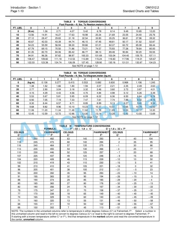
- 1.11. TIGHTEN TORQUE TABLE
- 1.12. COATING MATERIALS LIST
- 1.13. SELECTION OF WIRE ROPES USED FOR ASSEMBLY
- 1.14. SELECTION OF NYLON SLINGS USED FOR ASSEMBLY
- 1.15. ASSEMBLY PROCEDURE
- 1.15.1. A1 Installation of track shoe assembly
- 1.15.2. A2 Installation of machine body (chassis)
- 1.15.3. A3 Installation of operators cab assembly (When operator cab assembly is not installed)
- 1.15.4. A4 Installation of pivot shaft (When pivot shaft is not installed)
- 1.15.5. A5 Installation of final drive assembly
- 1.15.6. A6 Installation of undercover (When undercover is not installed)
- 1.15.7. A7 Installation of blade lift hydraulic cylinder
- 1.15.8. A8 Installation of undercarriage 1
- 1.15.9. A8 Installation of undercarriage 2
- 1.15.10. A9 Adding oil to pivot chamber
- 1.15.11. A10 Inspection of oil level and coolant level
- 1.15.12. A11 Installation of ripper1 (Machine with ripper)
- 1.15.13. A11 Installation of ripper2 (Machine with ripper)
- 1.15.14. A11 Installation of ripper3 (Machine with ripper)
- 1.15.15. A11 Installation of ripper4 (Machine with ripper)
- 1.15.16. A11 Installation of ripper5 (Machine with ripper)
- 1.15.17. A11 Installation of ripper6 (Machine with ripper)
- 1.15.18. A11 Installation of counterweight (Machine with counterweight)
- 1.15.19. A12 Installation of trunnion
- 1.15.20. A13 Installation of track
- 1.15.21. A14 Adjusting of track tension
- 1.15.22. A15 Installation of mask
- 1.15.23. A16 Installation of handrail / step on right side of radiator
- 1.15.24. A17 Installation of handrail / step on left side of radiator
- 1.15.25. A18 Instalation of cab right side cover (When cab right side cover is not installed)
- 1.15.26. A19 Instalation of cab left side cover (When cab left side cover is not installed)
- 1.15.27. A20 Assembling of blade unit1 (Machine with semiU blade/fullU blade)
- 1.15.28. A20 Assembling of blade unit2 (Machine with semiU blade/fullU blade)
- 1.15.29. A20 Assembling of blade unit3 (Machine with semiU blade/fullU blade)
- 1.15.30. A20 Assembling of blade unit4 (Machine with semiU blade/fullU blade)
- 1.15.31. A20 Assembling of blade unit5 (Machine with semiU blade/fullU blade)
- 1.15.32. A20 Assembling of blade unit1 (Machine with superdozer blade)
- 1.15.33. A20 Assembling of blade unit2 (Machine with superdozer blade)
- 1.15.34. A20 Assembling of blade unit3 (Machine with superdozer blade)
- 1.15.35. A20 Assembling of blade unit4 (Machine with superdozer blade)
- 1.15.36. A20 Assembling of blade unit5 (Machine with superdozer blade)
- 1.15.37. A21 Installation of blade assembly (Machine with semiU blade/fullU blade)
- 1.15.38. A21 Installation of blade assembly (Machine with superdozer blade)
- 1.15.39. A22 Installation of KOMTRAX antenna
- 1.15.40. A23 Installation of ROPS
- 1.15.41. A24 Installation of engine air intake port hood (When engine air intake port hood is not installed)
- 1.15.42. A25 Installation of precleaner (optional) (When precleaner is not installed)
- 1.15.43. A26 Installation of engine exhaust pipe (When engine exhaust pipe is not installed)
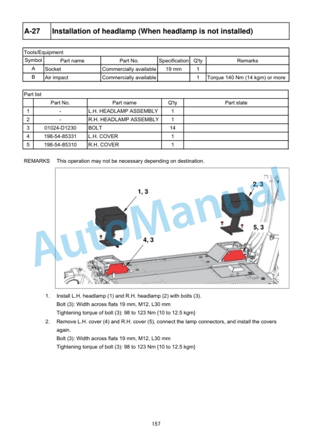
- 1.15.44. A27 Installation of headlamp (When headlamp is not installed)
- 1.15.45. A28 Installation of giant ripper shank
- 1.15.46. A29 Adjustment of blade tilt control angle (Machine with semiU blade/fullU blade)
- 1.15.47. A30 Adjustment of blade tilt control angle (Machine with superdozer)
- 1.15.48. A31 Blade pitch current value correction (Machine with superdozer)
- 1.15.49. A32 Installation of platform1
- 1.15.50. A32 Installation of platform2
- 1.15.51. A32 Installation of platform3
- 1.15.52. A32 Installation of platform4
- 1.15.53. A33 Greasing each part
- 1.15.54. A34 Bleeding air from hydraulic cylinder
- 1.15.55. A35 Bleeding air from work equipment pump and fan pump
- 1.15.56. A36 Installation of quick charge piping (optional)
- 1.15.57. A37 Installation of ladder 1 (For machine with ladder)
- 1.15.58. A37 Installation of ladder 2 (For machine with ladder)
- 1.15.59. A37 Installation of ladder 3 (For machine with ladder)
- 1.15.60. A37 Installation of ladder 4 (For machine with ladder)
- 1.15.61. A37 Installation of ladder 5 (For machine with ladder)
- 1.15.62. A38 Installation of ladder 1 (For machine with retrofitting ladder)
- 1.15.63. A38 Installation of ladder 2 (For machine with retrofitting ladder)
- 1.15.64. A38 Installation of ladder 3 (For machine with retrofitting ladder)
- 1.15.65. A38 Installation of ladder 4 (For machine with retrofitting ladder)
- 1.15.66. A38 Installation of ladder 5 (For machine with retrofitting ladder)
- 1.15.67. A38 Installation of ladder 6 (For machine with retrofitting ladder)
- 1.15.68. A39 Installation of access light and additional work lamp (optional)
- 1.15.69. A40 Installation of stroke sensing blade lift cylinder (For ICT specification)
- 1.15.70. A41 Installation of stroke sensor harness (When installing the ICT local modification kit)
- 1.15.71. A42 Installation of IMU sensor (When installing the ICT local modification kit)
- 1.15.72. A43 Installation of ICT harness (When installing the ICT local modification kit)
- 1.15.73. A44 Installation of AUX BOX (For ICT specification)
- 1.15.74. A45 Installation of navigation controller (When installing the ICT local modification kit)
- 1.15.75. A46 Installation of control box (When installing the ICT local modification kit)
- 1.15.76. A47 Installation of offset switch (When installing the ICT local modification kit)
- 1.16. CHECK AND MAINTENANCE PROCEDURES AFTER COMPLETION OF ASSEMBLY
- 1.16.1. M1 Checking machine monitor 1
- 1.16.2. M1 Checking machine monitor 2
- 1.16.3. M1 Checking machine monitor 3
- 1.16.4. M1 Checking machine monitor 4
- 1.16.5. M1 Checking machine monitor 5
- 1.16.6. M2 Adjustment menu
- 1.16.7. M3 Change of return filter (Standard filter Flushing filter)
- 1.16.8. M4 Flushing hydraulic circuit and bleeding air from cylinder 1
- 1.16.9. M5 Change of return filter (Flushing filter Standard filter)
- 1.16.10. M6 Bleeding air from cylinder 2
- 1.16.11. M7 How to start operation of KOMTRAX terminal and how to initializeKOMTRAX Plus controller
- 1.16.12. M8 Noinjection cranking of engine
- 1.16.13. M9 Calibration of cutting edge
- 1.17. APPENDIX 1 INSTALLATION OF SPILL GUARDS
- 1.18. APPENDIX 2 FIELD ASSEMBLY INSPECTION REPORT
- 1.19. APPENDIX 3 PmCLINIC
Komatsu Operation and Maintenance Manual PDF
Komatsu 503 Motor Grader Operation and Maintenance Manual 2079A-H45
Komatsu Operation and Maintenance Manual PDF
Komatsu 210M Dump Truck Operation and Maintenance Manual DG725
Komatsu Operation and Maintenance Manual PDF
Komatsu 330M Dump Truck Operation and Maintenance Manual DG745
Komatsu Operation and Maintenance Manual PDF
Komatsu 4D104E, S4D104E Series Diesel Motor Operation and Maintenance Manual WHBMNEF000
Komatsu Operation and Maintenance Manual PDF
Komatsu 730E Dump Truck Operation and Maintenance Manual CEAM018100
Komatsu Operation and Maintenance Manual PDF
Komatsu 210M Dump Truck Operation and Maintenance Manual DG692
Komatsu Operation and Maintenance Manual PDF
Komatsu 730E Dump Truck Operation and Maintenance Manual CEAM013300
Komatsu Operation and Maintenance Manual PDF
Komatsu 730E Dump Truck Operation and Maintenance Manual CEAM006700
Komatsu Operation and Maintenance Manual PDF
Komatsu 150A, 150FA Crane Operation and Maintenance Manual CEAMC20081
Komatsu Operation and Maintenance Manual PDF
Komatsu 210M Dump Truck Operation and Maintenance Manual DG615

