Claas Corio 880-670 Fc (H08) Combines Repair Manual EN
$300.00
- Model: Corio 880-670 Fc (H08) Combines
- Type Of Manual: Repair Manual
- Language: EN
- Format: PDF(s)
- Size: 74.5 MB
File List:
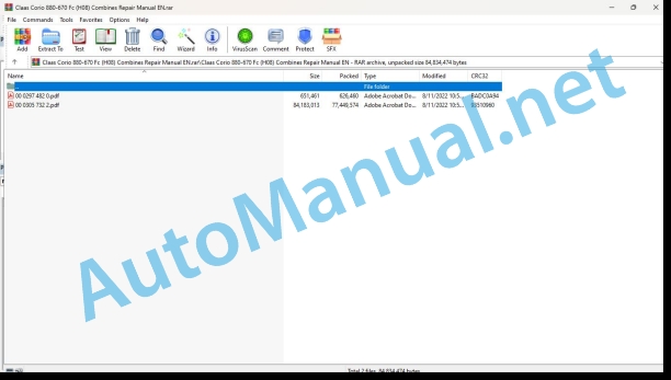
00 0297 482 0.pdf
00 0305 732 2.pdf
00 0305 732 2.pdf:
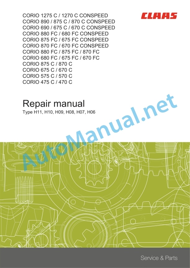
CORIO 1275 C / 1270 C CONSPEEDCORIO 890 / 875 C / 870 C CONSPEEDCORIO 690 / 675 C / 670 C CONSPEEDCORIO 880 FC / 680 FC CONSPEEDCORIO 875 FC / 675 FC CONSPEEDCORIO 870 FC / 670 FC CONSPEEDCORIO 880 FC / 875 FC / 870 FCCORIO 680 FC / 675 FC / 670 FCCORIO 875 C / 870 CCORIO 675 C / 670 CCORIO 575 C / 570 CCORIO 475 C / 470 C
Table of contents
Introduction
General information
Using the manual
Text and figures
Document structure based on sub-assemblies
Search and find
Directions
Abbreviations
Technical terms
Validity of manual
CCN (CLAAS Component Number)
Electric systems standard
Hydraulic system standard
General repair instructions
Technical specifications
Information on technically correct repairs
Self-locking bolts
Liquid locking compound
Steel roller chains
Tensioning
Chain connector
Chain connector type E with spring
Chain connector type G with wire
Chain connector type S with cotter pins
Taper ring fasteners
Dismounting
Installing
Gib head key connections
Dismounting
Installing
Lock collar bearing
Dismounting
Installing
Adapter sleeve bearing
Dismounting
Installing
Chuck bushing
Removing
Dismounting of version A
Dismounting of version B
Installing
Chuck bushing version A
Chuck bushing version B
Circlips
Radial shaft seals
Hose clamps
Tightening speed
Tightening torques
Alignment of clamps
Installation aids
Assembly tools
Ferrule fittings
Screwing in
Leaky ferrule fittings
Sealing cone fittings
Hydraulic hoses
Hose placement
Treatment of sealing faces
Spare parts
Operating materials
ESD protection measures
Special tool
ESD protection measures
Notes on inspection and repair
Tightening torques
Threaded assemblies according to CLAAS works standard CN 02 5000
Description of threaded assembly
Tolerance class
Tightening specifications
Tightening torques for metric ISO screw threads
Tightening torques for metric fine thread screws
Tightening torques for hydraulic fittings with ferrule
Tightening torques for pipe fittings with sealing cone joints and hydraulic fittings with soft ring seals
Tightening torques for bulkhead union nuts, straight and angled
Tightening torques for hydraulic male connectors SDS shape B and E
Tightening torques for hydraulic male connectors SDS shape F and screw plug
Tightening torques for SDS shape H hydraulic male connectors
Tightening torques for screw plugs shape E
Tightening torque for hydraulic male connectors shape C, conical thread
Tightening torques for hydraulic male connectors SDE shape F, adjustable direction
Tightening torques for hydraulic male connectors SDE shape H, with adjustable direction
Tightening torques for hydraulic swivel screw fittings
Tightening torque for hollow screws (with copper sealing ring)
Tightening torques for brake line screw fittings
Tightening torque for tubes with O-ring and union nuts
Tightening torques for threaded pins / orifice plates
Tightening torque for studs and special screws
Tightening torques for hydraulic components
Tightening torques for hex. sealing nuts
Tightening torques for hose clamps
Installation instructions
Worm drive hose clamps
Worm drive clamps with disc spring
Hose clamps with round pins
CCN explanation
CCN (CLAAS Component Number)
Electric system standard
Overview
Hydraulic system standard
Overview
CCN (CLAAS Component Number)
Identifying warnings
Hazard signs
Signal word
General information
Important
Identification of warning and danger signs
General safety and accident prevention regulations
Leaving the machine
Adjusting and maintenance work
Danger of injury from hydraulic liquid
Hydraulic accumulators
First-aid measures
Battery isolating switch
Putting the machine out of operation
Safety rules
Safety signs and warnings
Requirement made on technical staff
Children in danger
Hazard areas of the machine
Instructors travelling along during fieldwork
Risk of injury from rotating shafts
Structural alterations of the machine
Optional equipment and spare parts
Control of running machine
Technical condition
Respecting technical limit values
Danger from machine parts that continue rotating
Keeping safety devices functional
Personal protective equipment
Wearing suitable clothing
Removing dirt and loose objects
Parking the machine safely
Unsuitable operating utilities
Safe handling of service fluids and auxiliary utilities
Environmental protection and disposal
Keeping the cab free of chemicals
Avoiding fires
Potentially fatal electric shock from overhead lines and lightning strike
Electric shock from electric system
Noise may damage your health
Pre-loaded machine parts
Liquids under pressure
Compressed air
Toxic exhaust gases
Hot surfaces
Safe access and leaving
Working only on the stopped machine
Hazards during repairs
Raised machine parts and loads
Danger from welding work
Checking and charging the battery
Preparations for cases of emergency
02 Gearbox / Clutch / Universal drive shaft
0230 Mechanical gearbox
Gearbox overview
Technical specifications
Front attachment transmission
Technical specifications
Work preparation
Installation instructions
Removing the front attachment transmission
Installing the front attachment transmission
Angle drive
Technical specifications
Work preparation
Installation instructions
Removing the angle drive
Installing the angle drive
Short universal drive shaft
Technical specifications
Work preparation
Removing
Installing
0260 Universal drive shaft
Universal drive shaft
Technical specifications
Work preparation
Disassembling
Assembling
08 Drives
0800 Drive diagram
Drive diagram H11
Technical specifications
Drive diagram H10
Technical specifications
Drive diagram H09
Technical specifications
Drive diagram H08
Technical specifications
Drive diagram H07
Technical specifications
Drive diagram H06
Technical specifications
0808 Main drive
Drive mechanism H11
Technical specifications
Work preparation
Drive mechanism H10
Technical specifications
Work preparation
Drive mechanism H09
Technical specifications
Work preparation
Drive mechanism H08
Technical specifications
Work preparation
Drive mechanism H07 – H06
Technical specifications
Work preparation
Main drive
Technical specifications
Work preparation
Installation instructions
Removing the left outside drive shaft
Installing the left outside drive shaft
Removing the right outside drive shaft
Installing the right outside drive shaft
Removing the centre left drive shaft
Installing the centre left drive shaft
Removing the centre right drive shaft
Installing the centre right drive shaft
09 Hydraulic system
0900 Hydraulic system – General
Hydraulic system – General
Work preparation
Special tool
Damage of hydraulic system
Checking the pressure accumulator
0915 Hydraulic lines
Multi-coupler
Technical specifications
Work preparation
Repair kit
Auxiliary tool
Removing the male coupling
Disassembling the male coupling
Assembling the male coupling
Installing the male coupling
0920 Valves
Valve block, general
Special tool
Pulling out the valve insert
Unscrewing the iron core
Removing the sealing ring
Main valve block
Technical specifications
Installation instructions
Before removing any valve:
0930 Cylinders
Swinging hydraulic cylinder (3027)
Technical specifications
Work preparation
Removing
Installing
Picker lock hydraulic cylinder
Technical specifications
Work preparation
Removing
Installing
Hydraulic cylinder of hoods (3029)
Technical specifications
Work preparation
Installation instructions
Removing
Installing
Adjusting
0980 Hydraulic circuit diagram
CONSPEED 8R front attachment hydraulics
Technical specifications
CONSPEED 6R front attachment hydraulics
Technical specifications
CONSPEED 5R and 4R front attachment hydraulics
Technical specifications
10 Electrical / Electronic equipment
1000 Electrical / Electronic equipment general
Electrical / electronic equipment – General
Special tool
Preparing welding work
20 Crop feeding
2005 Crop dividers
Down maize auger
Technical specifications
Work preparation
Installation instructions
Removing
Disassembling
Assembling
Installing
Down-crop auger hydraulic motor (2040)
Technical specifications
Work preparation
Installation instructions
Removing
Disassembling
Assembling
Installing
21 Feeder unit
2140 Intake auger
Folding intake auger
Technical specifications
Work preparation
Auxiliary tool
Special tool
Installation instructions
Removing the right intake auger
Installing the right intake auger
Removing the left intake auger
Installing the left intake auger
Removing the centre intake auger
Installing the centre intake auger
Removing the intake auger clutch
Installing the intake auger clutch
Rigid intake auger
Technical specifications
Work preparation
Special tool
Installation instructions
Removing the bearing from the bearing cup
Intake auger extension
Technical specifications
Work preparation
Installation instructions
Removing
Installing
Intake auger drive
Technical specifications
Work preparation
Removing the chain
Installing the chain
Removing the top sprocket
Installing the top sprocket
Removing the chain tensioner
Disassembling the chain tensioner sprocket
Assembling the chain tensioner sprocket
Installing the chain tensioner
Removing the driving sprocket
Disassembling the bearing assembly
Assembling the bearing assembly
Installing the driving sprocket
24 Snapping device
2405 Snapping unit
Snapping unit
Technical specifications
Installation instructions:
Snapping plate adjustment sensor (B055)
Technical specifications
Removing the snapping plate adjustment sensor (B055)
Disassembling snapping plate adjustment sensor (B055)
Assembling snapping plate adjustment sensor (B055)
Installing snapping plate adjustment sensor (B055)
Technical specifications
Work preparation
Snapping plates
Technical specifications
Work preparation
Removing
Installing
Adjusting
Adjusting the snapping plates
Snapping plate adjustment
Technical specifications
Work preparation
Removing
Installing
Scraper plates H11 – H09
Technical specifications
Work preparation
Installation instructions
Removing the skids
Installing the skids
Scraper plates H08 – H06
Technical specifications
Work preparation
Installation instructions
Removing the skids
Installing the skids
Snapping rollers H11 – H09
Technical specifications
Work preparation
Special tool
Removing the snapping rollers
Removing the snapping roller augers
Installing the snapping rollers
Installing the snapping roller augers
Changing the snapping knives
Snapping rollers H08 – H06
Technical specifications
Work preparation
Removing the snapping rollers
Disassembling the snapping rollers
Assembling the snapping rollers
Installing the snapping rollers
Snapping chains
Technical specifications
Work preparation
Special tool
Removing
Installing
Adjusting the chain tension
Chopper unit
Technical specifications
Work preparation
Special tool
Changing the chopper knives
Chopper knives wear limit
Chopper knife fastening wear limit
Chopper knife mounting bolt
Chopper knives self-locking nut
Chopper knives bushing
Wear limits of knife carrier / retainer plate
Knife carriers
Retainer plate
Removing the knife carriers
Disassembling the knife carrier
Assembling the knife carrier
Installing the chopper unit
Snapping gearbox H11 – H09
Technical specifications
Work preparation
Auxiliary tool
Special tool
Removing the snapping gearbox
Disassembling snapping gearbox H11 – H09
Assembling snapping gearbox H11 – H09
Snapping roller drive
Main drive
Backlash and snapping roller drive contact pattern
Feeder chains drive
Backlash and contact pattern of snapping roller drive
Chopper unit drive
Installing snapping gearbox H11 – H09
Snapping gearbox H08 – H06
Technical specifications
Work preparation
Special tool
Removing the snapping gearbox
Disassembling the snapping gearbox
Assembling
Adjusting the backlash and the contact pattern
Installing
Snapping plate adjustment hydraulic cylinder (3030)
Technical specifications
Auxiliary tool
Work preparation
Removing
Installing
2410 Covers / Divider points
Outer points
Technical specifications
Work preparation
Installation instructions
Removing the divider points
Disassembling the crop divider points
Assembling the crop divider point
Installing the divider points
Inner hoods / points
Technical specifications
Work preparation
Removing the divider points
Removing the hoods
Removing the support
Installing the support
Installing the hoods
Installing the divider points
80 Various components / Machine body
8005 Frame / Trough
Swinging kinematics
Technical specifications
Work preparation
Installation instructions
Stubble breaker
Technical specifications
Work preparation
Installation instructions
8010 Locking
Technical specifications
Installation instructions
8020 Rails / Safety devices
Lower guard
Technical specifications
Work preparation
Dust shield
Technical specifications
Work preparation
Installation instructions
John Deere Repair Technical Manual PDF
John Deere Diesel Engines POWERTECH 2.9 L Component Technical Manual CTM126 Spanish
John Deere Repair Technical Manual PDF
John Deere Repair Technical Manual PDF
John Deere Repair Technical Manual PDF
John Deere PowerTech M 10.5 L and 12.5 L Diesel Engines COMPONENT TECHNICAL MANUAL CTM100 10MAY11
John Deere Repair Technical Manual PDF
John Deere Repair Technical Manual PDF
John Deere Repair Technical Manual PDF
John Deere Repair Technical Manual PDF
John Deere Parts Catalog PDF
John Deere Tractors 7500 Parts Catalog CPCQ26568 30 Jan 02 Portuguese
John Deere Repair Technical Manual PDF
John Deere 16, 18, 20 and 24HP Onan Engines Component Technical Manual CTM2 (19APR90)


