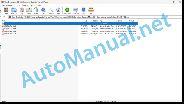
Claas Dominator 370 (556) Combines Operator Manual EN
$50.00
- Model: Dominator 370 (556) Combines
- Type Of Manual: Operator Manual
- Language: EN
- Format: PDF(s)
- Size: 130 MB
File List:
00 0288 854 5.pdf
00 0301 051 0.pdf
00 0303 482 0.pdf
00 0303 846 1.pdf
00 0288 854 5.pdf:
4LZ-12 (DOMINATOR 370)
Table of contents
1 Introduction
1.1 Notes on the manual
1.1.1 Manual Validity
1.1.2 Information concerning this user manual
1.1.3 Symbols and notes
1.1.4 Product Standard
1.1.5 Optional equipment
1.1.6 Qualified specialist workshop
1.1.7 Warranty notes
1.1.8 Spare parts and technical questions
1.2 Intended use
1.2.1 Intended use
1.2.2 Reasonably foreseeable misuse
2 Safety
2.1 Identifying warnings
2.1.1 Hazard signs
2.1.2 Signal word
2.2 Safety rules
2.2.1 Importance of Operator’s Manual
2.2.2 Observing safety decals and warnings
2.2.3 Requirements for all persons working with the machine
2.2.4 Children in danger
2.2.5 Hazard areas
2.2.6 Standing between machine and front attachment
2.2.7 Instructors on board during fieldwork
2.2.8 Fitting a front attachment or hitching a transport trailer to the machine
2.2.9 Danger of injury from rotating shafts
2.2.10 Structural alterations
2.2.11 Optional equipment and spare parts
2.2.12 Control of the machine while it is running
2.2.13 Operation only following proper putting into operation
2.2.14 Technical condition
2.2.15 Danger from damage to the machine
2.2.16 Complying with technical limit values
2.2.17 Hazard from machine parts that continue rotating
2.2.18 Keeping safety devices functional
2.2.19 Personal protective equipment
2.2.20 Wearing suitable clothing
2.2.21 Removing dirt and loose objects
2.2.22 Hazards when driving on the road and on the field
2.2.23 Parking the machine safely
2.2.24 Unsuitable operating utilities
2.2.25 Safe handling of operating and auxiliary utilities
2.2.26 Fuel is harmful to your health
2.2.27 Refrigerant is harmful to your health
2.2.28 Environmental protection and disposal
2.2.29 Avoiding fires
2.2.30 Possibly lethal electrocution from overhead lines
2.2.31 Behaviour in case of voltage flashover from overhead lines and of lightning strikes
2.2.32 Electrocution by electrical system
2.2.33 Noise may cause health damage
2.2.34 Oscillations may damage your health
2.2.35 Pressurised fluids
2.2.36 Compressed air
2.2.37 Toxic exhaust gas
2.2.38 Hot surfaces
2.2.39 Accessing and leaving the machine safely
2.2.40 Working on machine only after shutting it down
2.2.41 Maintenance operations and repair work
2.2.42 Raised machine parts and loads
2.2.43 Hazard from welding work
2.2.44 Checking and charging the battery
2.3 Safety marking
2.3.1 Structure of safety decals
2.3.2 Diesel engine warning icons
2.3.3 Fluid pressure system warning icons
2.3.4 Cab warning symbols
2.3.5 Feeder unit warning symbols
2.3.6 Threshing unit warning symbols
2.3.7 Separation unit warning symbols
2.3.8 Cleaning warning symbols
2.3.9 Crop discharge and straw discharge warning symbols
2.3.10 Grain delivery warning icons
2.3.11 Warning symbols on attachment parts and machine body
3 Machine description
3.1 Overview and method of operation
3.1.1 Overview of harvester front and left side
3.1.2 Overview of harvester rear and right side view
3.1.3 Overview of cylindrical separator system
3.1.4 Work principles of machines with cylindrical separator system
3.1.5 Diesel Engine Perkins 1106 D-E70TA Overview
3.1.6 Overview of Fuel tank
3.1.7 Overview of threshing concave
3.1.8 Overview of separator concave section
3.1.9 Overview of straw chopper*
3.1.10 Overview of tool box
3.1.11 Overview of key system
Standard key system
3.2 Optional equipment
3.2.1 4-TRAC*
3.3 Identification plates and identification numbers
3.3.1 Diesel Engine Perkins 1106 D-E70TA Model Number and Nameplate
3.3.2 Machine identification plate and environmental information plate
3.3.3 Machine identification plate and environmental information plate
3.3.4 Machine production serial number
3.3.5 Identification plate of drivers seat
3.3.6 Steering drive axle identification plate
3.4 Information on the machine
3.4.1 Chassis label
3.4.2 Grain recovery labels
3.4.3 Label for grain delivery
3.4.4 Detachable components and machine exterior labels
3.4.5 Hydraulic System Label
4 Operating and display elements
4.1 Cab and operator’s platform
4.1.1 Driving position
4.1.2 Control terminal
4.1.3 Cab top cover
4.1.4 B Column control terminal
4.1.5 Road travel lights and work lights
4.1.6 Steering column
4.1.7 Ignition switch
4.1.8 Standard multifunction handle
4.1.9 Air conditioning
4.1.10 Drivers seat
4.1.11 Camera system monitor*
4.1.12 Vehicle Window Glass Washing System Fluid Storage Tank
4.2 On-board computer and display units
4.2.1 CEBIS General note
4.2.2 Vehicle control display overview
4.2.3 Harvest di.2.4 NOTICE Information in CEBIS
NOTICE Information Types
NOTICE Structure of fault code information
Closing Fault Code Information
Consulting the warning history
Consulting the active warnings
4.2.5
4.2.6 Message fields symbols
4.3 CEBIS operation
4.3.1 CEBIS Operation scheme
4.3.2 Operation by touchscreen
4.3.3 Changing settings
5 Technical specifications
5.1 Technical Parameters
5.1.1 Major Machine Specifications
5.1.2 Major Machine Specifications
5.1.3 Major Machine Specifications
5.1.4 Major Machine Specifications
5.1.5 Major Machine Specifications
5.1.6 Major Machine Specifications
5.1.7 Major Machine Specifications
5.1.8 Major Machine Specifications
5.1.9 Machine Dimensions
5.1.10 Dimensions when the grain tank unloading tube is placed in the work position
5.1.11 Turning diameter
Measurement conditions
5.1.12 Sound pressure level and vibrations
5.1.13 Diesel engine of machine
5.1.14 Perkins 1106 D-E70TA
5.1.15 Chassis
5.1.16 Main drive axle wheelbase
5.1.17 Steering axle wheelbase
5.1.18 4WD steering axle wheelbase
5.1.19 Brakes
5.1.20 Diesel Engine Perkins 1106 D-E70TA battery
5.1.21 Machine threshing drum width
5.1.22 Machine threshing system
5.1.23 Threshing system
5.1.24 Drum-type separation system
5.1.25 Cleaner-grader
5.1.26 Crop deposition and straw deposition
5.1.27 Grain tank volume
5.1.28 Grain tank emptying power
5.2 Operating utilities
5.2.1 Lubricant
5.2.2 Coolant
5.2.3 Hydraulic oil
5.2.4 Fuel and Urea Solution Allowed for Use
6 Machine preparation
6.1 Switching off and securing the machine
6.1.1 Turn off machine and secure
6.2 Accessing workplaces and maintenance spaces
6.2.1 Entering the workplace
Entering the Workplace
6.2.2 Entering the maintenance space
Entering the Maintenance space
Entering the Maintee
Entering the Maintenance space
Entering the Maintenance space
6.2.3 Entering the Entry Zone
Entering the Entry Zone
Entering the Entry Zone
Entering the Entry Zone
Entering the Entry Zone
Entering the
Entering the Entry Zone
Entering the Entry Zone
6.2.4 Turning the Front Ladder Up and Down
Turning the Front Ladder Up to the Transport Position
Turning the Front Ladder Down to the Boarding Position
6.2.5 Using the rear access ladder
Moving the rear ladder to transport position
Moving the rear ladder to access position
Removing and fitting the rear ladder
6.3 Preparing the machine for driving
6.3.1 Preparing for road travel
6.3.2 Preparing for field work
6.4 Setting the machine for operation
justing the Machine Setting to Corn Collection
6.4.2 Adjusting the Machine from Corn Collection to Grain Collection
6.4.3 Adjusting the Machine Setting to Rice Collection
6.4.4 Adjusting the Machine from Rice Collection to Grain Collection
6.4.5 Using Machines Equipped with Rice Equipment
6.4.6 Threshing Table DOMINATOR 370
6.4.7 Using a machine fitted with rice equipment
6.4.8 Sieve pans table
6.4.9 Winter fuel for use at low temperatures
6.4.10 Threshing segment
6.4.11 Preconcave flaps
6.4.12 Rotor cover plates
6.4.13 Cleaning machines used for harvesting seed crops
6.5 Loading the machine
6.5.1 Loading and securing the machine
6.5.2 Removing the suspension rings
6.6 Front attachment
6.6.1 Detaching and installing additional equipment
6.6.2 Preparing the lock
6.6.3 Installing the locking pawl
6.6.4 Inspect the front attachment dampening accumulator
6.6.5 Execute all learning processes when changing front attachment
Learn the front attachment height limit position
6.7 Engine
6.7.1 Selection of Permitted Fuel
6.7.2 Pay attention to the fuel specification
6.7.3 Observing the fuel specification
6.7.4 Observing the urea specification
Use of the urea solution
Purity and standard of urea solution
Storage of urea solution in tanks and containers
Properties of urea solution at high and low outside temperatures
6.7.5 Adding Motor Oil
Filling with fuel
6.8 Chassis
6.8.1 Removing and Mounting Wheels
Removing the Wheels
Mounting the wheels
6.8.2 Jacking up the machine
6.8.3 Lifting the machine for swinging the rear axle
6.8.4 Adjusting the steering shaft from the transport position to the work position
6.8.5 Adjusting the Steering Shaft Wheel Span
Adjust the body release
6.9 Brake
6.9.1 Checking the parking brake
6.9.2 Checking the travel of the service brake pedal
6.10 Hitch
6.10.1 Installing the tow hook
6.10.2 Connecting a trailer
6.10.3 Unhitching the trailer
6.11 Hydraulic system
6.11.1 Identification of hydraulic oil
6.12 Electric and electronic system
6.12.1 Turning the battery breaker switch on and off
6.12.2 Installing the air conditioner compressor fuse
6.12.3 Adjusting the dipped beam
6.12.4 Changing over the road travel lights as a function of front attachment
6.12.5 Starting the standard key system
6.12.6 Spare keys
6.13 Cab and operator’s platform
6.13.1 Installing the short-range mirror*
6.13.2 Adjusting the short-range mirror*
6.13.3 Inspecting the visual field
6.13.4 Removing the cab transport safety equipment
6.13.5 Adjusting the Operating Resistance of the Control Bar
6.14 Feeder unit
6.14.1 Adjusting the feed path roller
6.14.2 Applying the feeder housing safety lock
6.14.3 Releasing the feeder housing safety lock
6.14.4 Checking the feed path slip-prevention strips
6.15 Threshing mechanism
6.15.1 Opening and closing the stone trap
6.15.2 Demounting and installing the stone trap
Demount the stone collection trough
Installing the stone collection trough
6.15.3 Opening and closing the drum inspection cover
6.15.4 Installing and removing the threshing stage
6.15.5 Checking the threshing concave section setting
Threshing concave section distance for wheat wire concave section N7/18*
Threshing concave section distance for rice nail-threshing concave section
Threshing concave section distance of corn round bar concave section
6.15.6 Installing and removing the threshing drum cover plate
6.15.7 Installing and Dismounting the Feed Drum Sawtooth Plates*
6.15.8 Installing the external wear plates of the feed drum*
6.16 Separation
6.16.1 Adjusting the separation drum speed on the multi-gear drive mechanism*
6.16.2 Removing and Installing the Separation Notch Plate
Installing the separation drum separation gratings
6.17 Cleaning system
6.17.1 Detaching the sieve pans
6.17.2 Installing the sieve pan
6.17.3 Inspecting the basic setup of the sieve pans
6.17.4 Covering/opening the residue return
6.18 Crop discharge and straw discharge
6.18.1 Adjusting the straw chopper low speed
6.18.2 Dismounting the Straw Chopper Stationary Knife
6.18.3 Adjusting the deflectors of deflector spreader
6.19 Grain delivery
6.19.1 Closing the release aperture on the grain tank
6.20 Assembly parts and machine body
6.20.1 Securing the machine against rolling away
6.20.2 Checking the back-up horn
7 Operation
7.1 Driving the machine
7.1.1 Pay attention to explanations related to road travel
7.1.2 Driving the machine
Driving the machine forward
Braking the machine
Stopping the machine
Driving backward
7.1.3 Switching the road travel switch
Turning the road travel switch to road travel
Turning the road travel switch to field travel
7.2 Front attachment
7.2.1 Setting the working width
7.2.2 Switching on the front attachment at the control terminal
7.2.3 Disengaging the front attachment at the control terminal
7.2.4 Shutting off the additional equipment using the multifunction handle
7.2.5 Additional equipment reversal
Additional equipment reversal
7.2.6 Adjusting the hinge plate circumferential speed
7.3 Engine
7.3.1 Setting the diesel engine speed
7.3.2 Turning on the diesel engine
Turning on the diesel engine
When the outside temperature is 0C to -10C, let the diesel engine and hydraulic system warm up.
When the outside temperature is -10C to -35C, let the diesel engine and hydraulic system warm up.
7.3.3 Switching off the diesel engine
7.3.4 Note on electronic engine management
7.4 Chassis
7.4.1 Shifting Gears
7.4.2 Turning on 4-TRAC*
7.4.3 Turning off 4-TRAC*
7.4.4 Driving properties
7.4.5 Towing the machine out of a hazard area
7.5 Brake
7.5.1 Using the foot brake to control the machine
king brake
7.5.3 Shutting off the parking brake
7.5.4 Coupling and uncoupling the service brake pedals
7.5.5 Parking the machine
7.6 Steering
7.6.1 Observing the steering behaviour
7.6.2 Adjusting the steering column
7.6.3 Adjusting the steering column
7.7 Electric and electronic system
7.7.1 Teaching-in the machine speed
7.7.2 Setting the slip limits
7.8 Cab and operator’s platform
7.8.1 Lighting afterglow function*
7.8.2 Latch the seatbelt
7.8.3 Bringing the air conditioner into operation
7.8.4 Adjusting the air conditioner air flow rate
7.8.5 Emergency exit
7.9 Ground guidance
7.9.1 Selecting ground adaption
CONTOUR* variant
AUTO CONTOUR* variant
7.9.2 Saving the standard cutting height / bearing pressure values
7.9.3 Adjusting AUTO CONTOUR* Sensitivity
7.10 Threshing mechanism
7.10.1 Engaging the threshing mechanism
7.10.2 Disengaging the threshing mechanism
7.10.3 Adjusting the speed of the threshing drum
7.10.4 Adjusting the speed zones of the threshing drum
7.11 Cleaning system
7.11.1 Manually adjusting the sieve pans
7.11.2 Adjusting cleaning fan speed
7.12 Crop discharge and straw discharge
7.12.1 Adjusting the board spreader slope
7.12.2 Manually adjust the straw chopping length by rotating the stationary knife.
7.12.3 Adjusting the Straw Chopper Stationary Knife
7.13 Grain delivery
7.13.1 Opening the grain tank cover
7.13.2 Adjusting the grain tank unloading auger cover plate
7.13.3 Checking the residue
7.13.4 Turning the grain tank unloading tube to the outside and inside
7.13.5 Turning the grain tank unloader on and off
8 Faults and remedies
8.1 CEBIS on-board computer
8.1.1 Outputs an active error code
8.1.2 Warning history display
Display all warnings
Display information
Meanings of codes and abbreviations
8.2 Engine
8.2.1 Faults of diesel engine
8.2.2 Stopping an overheated diesel engine
8.2.3 Draining the fuel
8.2.4 Overview of diesel engine problems
8.3 Hydraulic system
8.3.1 Manually lowering the additional equipment
8.4 Electric and electronic system
8.4.1 Opening the basic central electrics
8.4.2 Closing the basic central electrics.
8.4.3 Changing the lamp
8.4.4 Jump-starting the diesel engine of the machine using 1 battery
8.4.5 Basic central terminal compartment
8.4.6 Vehicle main fuse
8.5 Cab and operator’s platform
8.5.1 Overview of problems with air conditioner
8.6 Front attachment
8.6.1 List of front attachment faults
8.7 Feeder unit
8.7.1 Overview of feeder housing faults
8.8 Threshing mechanism
8.8.1 Overview of threshing mechanism faults
8.8.2 Threshing drum
8.9 Separation
8.9.1 List of separator unit faults
8.10 Cleaning system
8.10.1 Cleaner-grader fault list
8.11 Crop discharge and straw discharge
8.11.1 Overview of problems with crop and straw discharge
8.12 Grain delivery
8.12.1 Overview of problems with grain delivery
8.12.2 Installing the grain tank unloading shear bolt
9 Maintenance
9.1 Maintenance interval overview
9.1.1 Before harvesting
9.1.2 100 hours after the first operation
9.1.3 After the first 500 hours of operation
9.1.4 Every 10 hours or every day
9.1.5 Every 50 operating hours
9.1.6 Every 100 hours
9.1.7 Every 250 hours
9.1.8 Every 500 operating hours or every year
9.1.9 Every 1000 hours
9.1.10 Every 2000 hours
9.1.11 Every 2000 hours or every year
9.1.12 Every 2 years
9.1.13 Every 5 years
9.1.14 After harvest
9.2 Lubrication plan
9.2.1 Performing lubrication of the left-side lubrication points at every 50 hours of operation
9.2.2 Performing lubrication of the right-side lubrication points at every 50 hours of operation
9.2.3 Performing lubrication of the left-side lubrication points at every 100 hours of operation
9.2.4 Performing lubrication of the right-side lubrication points at every 100 hours of operation
9.2.5 Perform lubrication of the left-side lubrication points at every 250 hours of operation
9.2.6 Lubricate the right side lubrication points at every 250 hours of operation
9.2.7 Performing lubrication of the left-side lubrication points at every 500 hours of operation
9.2.8 Lubricating the right-side lubrication points at every 500 hours of operation
9.3 Engine
9.3.1 Cleaning the diesel engine and engine assemblies
9.3.2 Checking the diesel engine oil level
9.3.3 Changing the diesel engine oil and oil filter
Draining motor oil
Replacing the oil filter
Adding Motor Oil
9.3.4 Cleaning the emissions filter of the diesel engine
9.3.5 Changing the fuel filter on the diesel engine
9.3.6 Cleaning the fuel tank exhaust device
9.3.7 Purging the fuel system
9.3.8 Discharging the fuel pre-filter condensation
9.3.9 Checking the diesel engine coolant level
9.3.10 Checking the coolant anti-freeze effect
Use of ready-mixed coolant
Use of concentrated corrosion protection / anti-freeze agent
9.3.11 Replacing the diesel engine coolant
9.3.12 Adding diesel engine coolant
9.3.13 Checking the air tubes
9.3.14 Checking the coolant tubes
9.3.15 Cleaning the radiator safety cover
9.3.16 Cleaning the cooling assembly
9.3.17 Cleaning the diesel engine air filter
9.3.18 Replacing the engine air filter element of the diesel engine
9.3.19 Replacing the air filter safety cartridge of the diesel engine
9.3.20 Checking the fuel system for leaks
9.3.21 Preserving the diesel engine
9.4 Chassis
9.4.1 Checking the wheels and tires
9.4.2 Checking the wheel nuts and wheel bolts
Main drive axle
Steering shaft
Drive axle
9.4.3 Cleaning the main drive axle
9.4.4 Checking the main drive axle gearbox oil level
9.4.5 Changing the main drive axle gearbox oil
Draining motor oil
Adding motor oil
9.4.6 Checking the main drive axle manual transmission oil level
9.4.7 Changing the main drive axle manual transmission oil
Draining motor oil
Adding Motor Oil
9.4.8 Inspecting the Steering Drive Shaft* Planetary Gear Assembly Oil Level
9.5 Brake
9.5.1 Checking the brake fluid level
9.5.2 Checking the brake pads and brake discs
9.6 Drives
9.6.1 Checking the drive mechanism
9.6.2 Adjusting the spring-loaded cylinder
9.6.3 Adjusting the spring-loaded cylinder
9.6.4 Adjusting the spring-loaded cylinder
9.6.5 Adjusting the spring-loaded cylinder
9.6.6 Adjusting the spring-loaded cylinder
9.6.7 Detaching the belt (R01)
9.6.8 Installing the belt (R01)
9.6.9 Detaching the belt (R02)
9.6.10 Installing the belt (R02)
9.6.11 Detaching the belt (R04)
9.6.12 Installing the belt (R04)
9.6.13 Adjusting the belt (R04)
9.6.14 Detaching the belt (R05)
9.6.15 Checking the belt (R05)
9.6.16 Installing the belt (R05)
9.6.17 Detaching the belt (R06)
Work Preparation
9.6.18 Installing the belt (R06)
9.6.19 Adjusting the belt (R06)
9.6.20 Detaching the belt (R07)
9.6.21 Installing the belt (R07)
9.6.22 Adjusting belt (R07)
9.6.23 Detaching the belt (R08)
9.6.24 Installing the belt (R08)
9.6.25 Detaching the belt (R17)
9.6.26 Installing the belt (R17)
9.6.27 Detaching the belt (R22)
9.6.28 Installing the belt (R22)
9.6.29 Detaching the belt (R23)
9.6.30 Installing the belt (R23)
9.6.31 Detaching the belt (R25)
9.6.32 Installing the belt (R25)
9.6.33 Detaching the bottom belt (R26)
9.6.34 Installing the rear belt (R26)
9.6.35 Adjusting the rear belt (R26)
9.6.36 Detaching the belt (R27)
9.6.37 Installing the belt (R27)
9.6.38 Adjusting the belt (R27)
9.6.39 Removing belt (R42)
Work preparation
Special tool
9.6.40 Installing belt (R42)
9.6.41 Detaching the belt (R43)
9.6.42 Installing the belt (R43)
9.6.43 Detaching the belt (R45)
9.6.44 Installing the belt (R45)
Adjustment
9.6.45 Detaching the belt (R50)
9.6.46 Installing the belt (R50)
Adjustment
9.6.47 Detaching the chain (K11)
9.6.48 Installing the chain (K11)
9.6.49 Detaching the chain (K57)
9.6.50 Installing the chain (K57)
9.6.51 Adjusting the chain (K57)
9.6.52 Detaching the chain (K58)
9.6.53 Installing the chain (K58)
9.6.54 Adjusting the chain (K58)
9.7 Hydraulic system
9.7.1 Checking the hydraulic system tightness
9.7.2 Checking the hydraulic hoses
9.7.3 Checking the hydraulic oil level
9.7.4 Replacing the hydraulic oil and filter
Draining motor oil
Adding Motor Oil
9.7.5 Replacing the filling screen of the hydraulic oil tank
9.7.6 Bleeding the front attachment cross levelling and the folding frame hydraulic cylinders
9.8 Cab and operator’s platform
9.8.1 Cleaning and changing the cab air filter
9.8.2 Cleaning the cab air recirculation filter
9.8.3 Checking for water saturation in the AC filter dryer
9.8.4 Checking the air conditioner tubes
9.9 Electric and electronic system
9.9.1 Electric system
9.9.2 Shutting off the battery breaker switch
9.9.3 Checking the battery usage status
9.9.4 Welding work on combine harvester
9.10 Feeder unit
9.10.1 Adjusting the feeder chain
9.10.2 Checking the friction pads on the feed path
9.11 Threshing mechanism
9.11.1 Checking the returns elevator chain
9.12 Separation
9.12.1 Checking the separation drum gearbox oil level
9.12.2 Replacing the separation drum gearbox oil
Draining motor oil
Adding Motor Oil
9.13 Crop discharge and straw discharge
9.13.1 Checking the straw chopper
9.13.2 Replacing the flail knives of the straw chopper
Replacing worn-out flail knives
For example: Replacing outside flail knives
For example: Replacing inside flail knives
Replacing grain flail knives
Replacing the corn flail knives
9.13.3 Dismounting the straw guide plate
9.14 Grain delivery
9.14.1 Checking the grain tank unloading gearbox oil level
9.14.2 Changing the grain tank unloading gearbox oil
Draining the oil
Topping up oil
9.14.3 Checking the grain elevator chain
9.14.4 Cleaning the auger trough
9.14.5 Cleaning the grain tank
9.14.6 Checking the transport position of the grain tank emptying tube
9.15 Assembly parts and machine body
9.15.1 Checking the tightness of gearboxes
9.15.2 Cleaning the machine
Cleaning the reflectors
Cleaning the lubrication nozzle
Cleaning the bearing points
Salt-cleaning the machine
9.15.3 Inspecting the fire extinguisher
9.15.4 Storing the machine
10 Putting out of operation and disposal
10.1 General information
10.1.1 Removal from service and disposal
11 Technical terms and abbreviations
11.1 Technical terms and abbreviations
11.1.1 Abbreviations
12 CCN explanation
12.1 CCN (CLAAS Component Number)
12.1.1 General
12.1.2 Electric system standard
Overview
12.1.3 Hydraulic system standard
Overview
13 CCN (CLAAS Component Number)
00 0301 051 0.pdf:
PROFI CAM 3
Table of contents
1 Introduction
1.1 Notes on the manual
1.1.1 Validity of manual
1.1.2 Information about this Operator’s Manual
1.1.3 Symbols and notes
1.1.4 Optional equipment
1.1.5 Qualified specialist workshop
1.1.6 Maintenance information
1.1.7 Warranty notes
1.1.8 Spare parts and technical questions
1.2 Intended use
1.2.1 Intended use
1.2.2 Reasonably foreseeable misuse
2 Safety
2.1 Identifying warnings
2.1.1 Hazard signs
2.1.2 Signal word
2.2 Safety rules
2.2.1 Meaning of Operator’s Manual
2.2.2 Observing safety decals and warnings
2.2.3 Optional equipment and spare parts
3 Product description
3.1 Overview and method of operation
3.1.1 How the PROFI CAM works
3.2 Identification plates and identification number
3.2.1 Position of identification plates
3.2.2 Explanation of PROFI CAM identification plate
3.3 Information on the product
3.3.1 CE marking
4 Operating and control elements
4.1 Camera system
4.1.1 Camera system monitor
4.2 Menu structure
4.2.1 Main menu
4.2.2
4.2.3
4.2.4
4.2.5
4.2.6
5 Technical specifications
5.1 PROFI CAM
5.1.1 Monitor
5.1.2 Camera
5.1.3 Switch box
5.1.4 Degree of protection against foreign bodies and water
6 Preparing the product
6.1 Shutting down and securing the machine
6.1.1 Switching off and securing the machine
6.2 Prior to operation
6.2.1 Carry out prior to operation
6.2.2 Installing the sun protection
6.2.3 Aligning the camera
6.2.4 Connecting the camera electrics
7 Operation
7.1 Monitor
7.1.1 Switching on the monitor
7.1.2 Calling up the menu
7.1.3 Setting a menu item
7.1.4 Setting the image orientation
7.1.5 Setting automatic screen darkening
7.1.6 Image mirroring
7.1.7 Setting the trigger view
7.1.8 Setting the follow-up time for trigger view
7.1.9 Setting the display mode
7.1.10 Activating/deactivating a display mode
8 Faults and remedies
8.1 Electrical and electronic system
8.1.1 Overview of problems on PROFI CAM camera system
8.1.2 Replacing the switch box fuse
9 Maintenance
9.1 Maintenance intervals
9.1.1 Every 10 operating hours or daily
9.2 Camera system
9.2.1 Checking the camera system for dirt
9.2.2 Cleaning the camera
9.2.3 Cleaning the switch box
9.2.4 Cleaning the monitor
10 Placing out of operation and disposal
10.1 General Information
10.1.1 Putting out of operation and disposal
11 Technical terms and abbreviations
11.1 Abbreviations
11.1.1 Units
11.1.2 Abbreviations
11.1.3 Technical terms
00 0303 482 0.pdf:
PROFI CAM 4
Table of contents
1 Introduction
1.1 Notes on the manual
1.1.1 Validity of manual
1.1.2 Information about this Operator’s Manual
1.1.3 Symbols and notes
1.1.4 Optional equipment
1.1.5 Qualified specialist workshop
1.1.6 Maintenance information
1.1.7 Notes on warranty
1.1.8 Spare parts and technical questions
1.2 Intended use
1.2.1 Intended use
1.2.2 Reasonably foreseeable misuse
2 Safety
2.1 Identifying warnings
2.1.1 Hazard signs
2.1.2 Signal word
2.2 Safety rules
2.2.1 Meaning of Operator’s Manual
2.2.2 Structural changes
2.2.3 Optional equipment and spare parts
2.2.4 Operation only following proper putting into operation
2.2.5 Technical status
2.2.6 Respecting technical limit values
Respecting technical limit values
2.2.7 Hazards when driving on roads and fields
3 Product description
3.1 Overview and method of operation
3.1.1 How the PROFI CAM works
3.2 Identification plates and identification number
3.2.1 Identification plates
3.3 Information on the product
3.3.1 CE marking
4 Operating and display elements
4.1 Camera system
4.1.1 Camera system monitor
4.1.2 CEBIS
4.2 Menu structure
4.2.1 Main menu
4.2.2
4.2.3
4.2.4
4.2.5
4.2.6
5 Technical specifications
5.1 PROFI CAM
5.1.1 Monitor
5.1.2 Camera
5.1.3 Switch box
6 Preparing the product
6.1 Switching off and securing the machine
6.1.1 Switching off and securing the machine
6.2 Prior to putting into operation
6.2.1 Carry out prior to operation
6.2.2 Installing the sun protection
6.2.3 Aligning the camera
7 Operation
7.1 Monitor
7.1.1 Switching on the monitor
7.1.2 Calling up the menu
7.1.3 Setting a menu item
7.1.4 Setting the image orientation
7.1.5 Setting automatic screen darkening
7.1.6 Image mirroring
7.1.7 Setting the trigger view
7.1.8 Setting the follow-up time for trigger view
7.1.9 Setting the display mode
7.1.10 Activating/deactivating a display mode
8 Faults and remedies
8.1 Electric and electronic system
8.1.1 Overview of problems on PROFI CAM camera system
9 Maintenance
9.1 Maintenance intervals
9.1.1 Every 10 operating hours or daily
9.2 Camera system
9.2.1 Checking the camera system for dirt
9.2.2 Cleaning the camera
9.2.3 Cleaning the switch box
9.2.4 Cleaning the monitor
10 Putting out of operation and disposal
10.1 General information
10.1.1 Putting out of operation and disposal
11 Technical terms and abbreviations
11.1 Abbreviations
11.1.1 Units
11.1.2 Abbreviations
11.1.3 Technical terms
00 0303 846 1.pdf:
DOMINATOR 40 WHEEL
Table of contents
1 To this Operator’s Manual
1.1 Notes on the manual
1.1.1 Validity of manual
1.1.2 Notes on the Operator’s Manual
1.1.3 Symbols and notices
1.1.4 Optional equipment
1.1.5 Qualified specialist workshop
1.1.6 Notes on maintenance
1.1.7 Notes on warranty
1.1.8 Technical specifications
1.1.9 Spare parts and technical questions
2 Safety
2.1 Intended use
2.1.1 Intended use
2.1.2 Reasonably foreseeable misuse
2.2 Safety rules
2.2.1 Operator’s Manual and other sources of information
Meaning of Operator’s Manual
2.2.2 Personnel qualification and organization
Requirements made on all persons working with the machine
2.2.3 Hazard for children
Children in danger
2.2.4 Modifications on the machine
Structural modifications
2.2.5 Additional equipment and spare parts
Additional equipment and spare parts
2.2.6 Workplace and persons travelling on the machine
Control of running machine
2.2.7 Technically flawless c
John Deere Repair Technical Manual PDF
John Deere Repair Technical Manual PDF
John Deere Repair Technical Manual PDF
John Deere Repair Technical Manual PDF
John Deere Repair Technical Manual PDF
John Deere PowerTech M 10.5 L and 12.5 L Diesel Engines COMPONENT TECHNICAL MANUAL CTM100 10MAY11
John Deere Repair Technical Manual PDF
John Deere Diesel Engines POWERTECH 2.9 L Component Technical Manual CTM126 Spanish
John Deere Repair Technical Manual PDF
John Deere Repair Technical Manual PDF
John Deere Repair Technical Manual PDF
John Deere POWERTECH E 4.5 and 6.8 L Diesel Engines TECHNICAL MANUAL 25JAN08
John Deere Repair Technical Manual PDF

