Claas Vario 930-500 Cerio 930-560 (528) Combines Operator Manual EN
$50.00
- Model: Vario 930-500 Cerio 930-560 (528) Combines
- Type Of Manual: Operator Manual
- Language: EN
- Format: PDF(s)
- Size: 56.8 MB
File List:
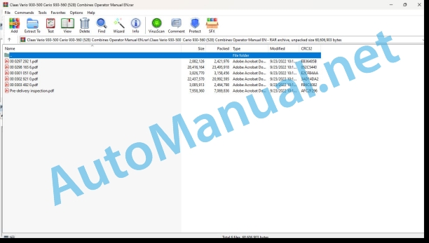
00 0297 292 1.pdf
00 0298 165 6.pdf
00 0301 051 0.pdf
00 0302 921 0.pdf
00 0303 482 0.pdf
Pre-delivery inspection.pdf
00 0297 292 1.pdf:
VARIO 1250 / 1050MAXFLEX 1250 / 1050MAXFLO 1250 / 1050C900 – C450V900 – V540
Table of contents
1 Introduction
1.1 Notes on the manual
1.1.1 Validity of manual
1.1.2 Notes on the Operator’s Manual
2.1 Identifying warnings
2.1.1 Hazard signs
2.1.2 Signal word
2.2 Safety rules
2.2.1 Operator’s Manual and other sources of information
Meaning of Operator’s Manual
2.2.2 Invisible laser radiation of laser class 1M
2.2.3 Intended use
3 Technical specifications
3.1 LASER PILOT
3.1.1 LASER PILOT
4 Operation
4.1 Steering
4.1.1 Folding out the LASER PILOT
4.1.2 Adjusting the LASER PILOT
Preparing the field
Adjusting the LASER PILOT to the crop
Adjusting the LASER PILOT to the crop
Preparing the adjusting procedure
Checking the LASER PILOT setting
Adjusting the LASER PILOT vertically
Checking the horizontal LASER PILOT pre-setting
Fine-adjusting the LASER PILOT horizontally
5 Faults and remedies
5.1 Overview of faults
5.1.1 LASER PILOT
00 0298 165 6.pdf:
VARIO 930 / 770 / 680 / 620 / 560 / 500CERIO 930 / 770 / 680 / 620 / 560
Table of contents
1 Introduction
1.1 Notes on the manual
1.1.1 Validity of manual
1.1.2 Information about this Operator’s Manual
1.1.3 Symbols and notes
1.1.4 Optional equipment
1.1.5 Qualified specialist workshop
1.1.6 Maintenance notes
1.1.7 Warranty notes
1.1.8 Spare parts and technical questions
1.2 Intended use
1.2.1 Intended use
1.2.2 Reasonably foreseeable misuse
2.1 Identifying warnings
2.1.1 Hazard signs
2.1.2 Signal word
2.2 Safety rules
2.2.1 Importance of Operator’s Manual
2.2.2 Observing safety decals and warnings
2.2.3 Requirements for all persons working with the machine
2.2.4 Hazard areas
2.2.5 Standing between machine and front attachment
2.2.6 Persons riding on the machine
2.2.7 Fitting a front attachment or hitching a transport trailer to the machine
2.2.8 Danger of injury from rotating shafts
2.2.9 Structural changes
2.2.10 Optional equipment and spare parts
2.2.11 Operation only following proper putting into operation
2.2.12 Technical condition
2.2.13 Danger from damage to the machine
2.2.14 Keeping the safety devices functional
2.2.15 Personal protective equipment
2.2.16 Wearing suitable clothing
2.2.17 Removing dirt and loose objects
2.2.18 Preparing the machine for road travel
2.2.19 Unsuitable operating utilities
2.2.20 Safe handling of operating materials and auxiliary materials
2.2.21 Environmental protection and disposal
2.2.22 Electrocution by electrical system
2.2.23 Pressurised fluids
2.2.24 Only carry out work on the machine when it is stopped
2.2.25 Maintenance operations and repair work
2.2.26 Raised machine parts and loads
2.2.27 Hazard from welding work
2.3 Safety marking
2.3.1 Layout of safety decals
2.3.2 Safety decals on the front attachment
3 Machine description
3.1 Overview and method of operation
3.1.1 Overview of machine
3.1.2 Storing the Operator’s Manual
3.1.3 Function of VARIO
3.1.4 Function of CERIO
3.1.5 Function principle of overload protection features
3.2 Optional machine equipment
3.2.1 Outer reel tines
3.2.2 CLAAS AUTO CONTOUR sensor band
3.2.3 Stone trap front plate
3.2.4 Scraper
3.2.5 Anti-wrap guard
3.2.6 Extension of outer deflectors
3.2.7 Lighting
3.2.8 Rapeseed separating knife
3.2.9 Rape cutting equipment transport box
3.3 Identification plates and identification numbers
3.3.1 Identification plate of front attachment
3.4 Information on the machine
3.4.1 Decal
4 Operating and display elements
4.1 Cab and operator’s platform
4.1.1 Control terminal
4.2 Front attachment
4.2.1 Controls
5 Technical specifications
5.1 VARIO / CERIO
5.1.1 Compatible machines
5.1.2 Dimensions
5.1.3 Weights
5.1.4 Cutting widths
5.1.5 Reel
5.1.6 Intake auger
5.2 Operating utilities
5.2.1 Lubricants
5.2.2 Hydraulic oil
6 Machine preparation
6.1 Switching off and securing the machine
6.1.1 Switching off and securing the machine
6.2 Loading the front attachment
6.2.1 Loading and lashing down the front attachment
6.3 Mounting the front attachment
6.3.1 Installing the front attachment
6.3.2 Preparing the locking
6.3.3 Suspending the front attachment
6.3.4 Locking the front attachment
6.3.5 Installing the universal drive shaft
6.3.6 Fitting the universal drive shaft guard chain
6.3.7 Mounting the multi-coupler
6.3.8 Removing the stands
6.3.9 Setting the front attachment in the on-board information system of the combine harvester
6.4 Removing the front attachment
6.4.1 Removing the front attachment
6.4.2 Fitting the stands
6.4.3 Removing the multi-coupler
6.4.4 Removing the universal drive shaft
6.4.5 Unlocking the front attachment
6.4.6 Unhinging the front attachment
6.5 Crop feeding
6.5.1 Fitting the reel safety lock
6.5.2 Unlocking the reel safety locks
6.5.3 Adjusting the cutterbar table position
6.6 Intake auger
6.6.1 Adapting the scraper profiles to the feeder housing
6.7 Mower unit
6.7.1 Fitting the finger bar safety device
6.7.2 Installing the rice cutting system*
Checking the hold-down clips
7 Operation
7.1 Driving the machine
7.1.1 Preparing road travel
7.1.2 Preparing fieldwork
7.1.3 Adjusting the parking position
7.1.4 Adjusting the parking position manually
7.2 Fieldwork
7.2.1 Prior to fieldwork
7.2.2 Adjusting the working position
7.2.3 Checking the crop pick-up
7.3 Rape harvest
7.3.1 Installing the rape cutting equipment*
7.3.2 Fitting the rape seed separating knife*
7.3.3 Connecting the rape cutting equipment* to the hydraulic system
Right side
7.4 Grain harvest
7.4.1 Fitting the grain equipment
7.4.2 Disconnecting the rape cutting equipment* from the hydraulic system
Right side
7.4.3 Removing the rape seed separating knife*
7.5 Intake auger
7.5.1 Adjusting the scraper profiles of the intake auger
7.5.2 Adjusting the intake auger position
7.5.3 Adjusting the intake auger fingers
7.5.4 Removing the auger plate extensions
7.5.5 Installing the auger plate extensions
7.5.6 Change the speed of the intake auger
7.6 Steering
7.6.1 Folding out the LASER PILOT*
7.6.2 Folding in the LASER PILOT*
7.7 Electric and electronic system
7.7.1 Switching the lighting equipment* on and off
Controlling the lighting equipment on the front attachment
Controlling the lighting equipment from the cab
7.8 Crop feeding
7.8.1 Fitting the crop dividers
7.8.2 Removing the crop dividers
7.8.3 Adjusting the long crop divider
7.8.4 Folding out the long crop divider
7.8.5 Folding in the long crop divider
7.8.6 Installing the outer deflector
7.8.7 Removing the outer deflector
7.8.8 Fitting the feed plate
7.8.9 Removing the feed plate
7.8.10 Adjusting the short crop divider
7.8.11 Folding out the short crop divider
7.8.12 Folding in the short crop divider
7.8.13 Adjusting the cutterbar table position from the cab
7.8.14 Adjusting the cutterbar table position on the front attachment
7.8.15 Adjusting the reel tines
7.8.16 Closing the cleaning aperture
7.9 Mower unit
7.9.1 Activating the rape cutting knives*
7.9.2 Installing and removing the crop lifter with quick-release coupling
Installing crop lifters
Removing the crop lifter
7.9.3 Installing crop lifters
7.9.4 Removing the crop lifters
7.10 Ground guidance
7.10.1 Adjusting the skids
7.10.2 Adjusting the skid plates with the quick adjustment mechanism*
8 Faults and remedies
8.1 Overview of problems
8.1.1 Improving crop flow
8.1.2 Crop pick-up
8.1.3 Intake auger
8.1.4 Mower unit
8.1.5 Ground guidance
8.2 Hydraulic system
8.2.1 Compensating the reel hydraulic cylinders
Compensating automatically
Compensating manually
8.2.2 Bleeding the cutterbar table adjustment hydraulic cylinders
8.3 Electric and electronic system
8.3.1 Preparing welding work
8.3.2 Adjusting the reel speed sensor
8.3.3 Adjust the position of the rape cutter towards the proximity sensor
8.4 Crop feeding
8.4.1 Making the basic VARIO reel height setting
8.4.2 Making the basic CERIO reel height setting
8.4.3 Replacing the reel tines
8.5 Intake auger
8.5.1 Changing the intake auger fingers with quick-release coupling
8.5.2 Changing the intake auger fingers
8.5.3 Removing the dust shield plate
9 Maintenance
9.1 Maintenance intervals
9.1.1 Before the harvest
9.1.2 After the first 100 operating hours
9.1.3 Every 10 operating hours or daily
9.1.4 Every 50 operating hours
9.1.5 Every 100 operating hours
9.1.6 Every 250 operating hours
9.1.7 Every 500 operating hours or annually
9.1.8 After the harvest
9.1.9 Preserving the front attachment
9.2 Lubrication plan
9.2.1 Grease the grease points every 10 operating hours
Applies to: MONTANA
9.2.2 Grease points, grease every 100 working hours
9.2.3 Grease the grease points every 250 operating hours
9.3 Transmission, clutch and driveshaft
9.3.1 Checking the spur angular gearbox oil level
9.3.2 Changing the spur angular gearbox oil
Draining the oil
Topping up oil
9.4 Drives
9.4.1 Adjusting the drives
9.4.2 Adjusting chain (K01)
9.4.3 Removing chain (K01)
9.4.4 Installing chain (K01)
9.4.5 Adjusting chain (K02)
9.4.6 Removing chain (K02)
9.4.7 Installing chain (K02)
9.5 Hydraulic system
9.5.1 Identifying the hydraulic oil
9.5.2 Checking the hydraulic oil level
9.5.3 Draining the hydraulic oil
9.5.4 Replacing the hydraulic system return-line filter
9.5.5 Topping up hydraulic oil
9.5.6 Checking the hydraulic hoses
9.6 Crop feeding
9.6.1 Checking the slide bars
9.6.2 Adjusting the slide bars
9.6.3 Cleaning the slide bars
9.6.4 Cleaning the skids
9.6.5 Cleaning the cutterbar table
9.6.6 Cleaning the cover plates
9.6.7 Checking the gas struts
9.7 Mower unit
9.7.1 Changing the knives
9.7.2 Changing the segmented knife
Installing the knife connection
Assembling cutterbar sections (A) with reinforcing plate
Assembling cutterbar sections (B) without reinforcing plate
9.7.3 Checking the crop guards
Checking the low crop guards
Checking the wear plate
Check wear of high crop guard
Checking the high crop guard
9.7.4 Checking the hold-down clips
9.7.5 Checking the hold-down clips
Checking the high hold-down clips’ wear plates
Checking the high hold-down clip’ wear
Checking the high hold-down clips
9.7.6 Replacing the knife section
9.7.7 Replacing the double fingers
9.7.8 Changing the knives of the rapeseed separating knives*
Removing the knives
Installing the knives
9.7.9 Cleaning the guide straps of the rapeseed separating knives*
10 Putting out of operation and disposal
10.1 General information
10.1.1 Decommissioning and disposal
11 Declaration of Conformity
11.1 Front attachment
11.1.1 EC declaration of conformity
11.1.2 UK Declaration of Conformity
00 0301 051 0.pdf:
PROFI CAM 3
Table of contents
1 Introduction
1.1 Notes on the manual
1.1.1 Validity of manual
1.1.2 Information about this Operator’s Manual
1.1.3 Symbols and notes
1.1.4 Optional equipment
1.1.5 Qualified specialist workshop
1.1.6 Maintenance information
1.1.7 Warranty notes
1.1.8 Spare parts and technical questions
1.2 Intended use
1.2.1 Intended use
1.2.2 Reasonably foreseeable misuse
2.1 Identifying warnings
2.1.1 Hazard signs
2.1.2 Signal word
2.2 Safety rules
2.2.1 Meaning of Operator’s Manual
2.2.2 Observing safety decals and warnings
2.2.3 Optional equipment and spare parts
3 Product description
3.1 Overview and method of operation
3.1.1 How the PROFI CAM works
3.2 Identification plates and identification number
3.2.1 Position of identification plates
3.2.2 Explanation of PROFI CAM identification plate
3.3 Information on the product
3.3.1 CE marking
4 Operating and control elements
4.1 Camera system
4.1.1 Camera system monitor
4.2 Menu structure
4.2.1 Main menu
4.2.2
4.2.3
4.2.4
4.2.5
4.2.6
5 Technical specifications
5.1 PROFI CAM
5.1.1 Monitor
5.1.2 Camera
5.1.3 Switch box
5.1.4 Degree of protection against foreign bodies and water
6 Preparing the product
6.1 Shutting down and securing the machine
6.1.1 Switching off and securing the machine
6.2 Prior to operation
6.2.1 Carry out prior to operation
6.2.2 Installing the sun protection
6.2.3 Aligning the camera
6.2.4 Connecting the camera electrics
7 Operation
7.1 Monitor
7.1.1 Switching on the monitor
7.1.2 Calling up the menu
7.1.3 Setting a menu item
7.1.4 Setting the image orientation
7.1.5 Setting automatic screen darkening
7.1.6 Image mirroring
7.1.7 Setting the trigger view
7.1.8 Setting the follow-up time for trigger view
7.1.9 Setting the display mode
7.1.10 Activating/deactivating a display mode
8 Faults and remedies
8.1 Electrical and electronic system
8.1.1 Overview of problems on PROFI CAM camera system
8.1.2 Replacing the switch box fuse
9 Maintenance
9.1 Maintenance intervals
9.1.1 Every 10 operating hours or daily
9.2 Camera system
9.2.1 Checking the camera system for dirt
9.2.2 Cleaning the camera
9.2.3 Cleaning the switch box
9.2.4 Cleaning the monitor
10 Placing out of operation and disposal
10.1 General Information
10.1.1 Putting out of operation and disposal
11 Technical terms and abbreviations
11.1 Abbreviations
11.1.1 Units
11.1.2 Abbreviations
11.1.3 Technical terms
00 0302 921 0.pdf:
CUTTERBAR C430
Table of contents
1 Introduction
1.1 Notes on the manual
1.1.1 Validity of this manual
1.1.2 Information about this Operator’s Manual
1.1.3 Symbols and notices
1.1.4 Optional equipment
1.1.5 Qualified specialist workshop
1.1.6 Notes on maintenance
1.1.7 Notes on warranty
1.1.8 Spare parts and technical questions
1.2 Intended use
1.2.1 Intended use
1.2.2 Reasonably foreseeable misuse
2.1 Identifying warnings
2.1.1 Hazard signs
2.1.2 Signal word
2.2 Safety rules
2.2.1 Meaning of Operator’s Manual
2.2.2 Observing safety decals and warnings
2.2.3 Requirements for all persons working with the machine
2.2.4 Hazard areas
2.2.5 Standing between the machine and the front attachment
2.2.6 Coupling of machine with front attachment or transport trailer
2.2.7 Danger of injury from rotating shafts
2.2.8 Structural changes
2.2.9 Optional equipment and spare parts
2.2.10 Operation only following proper putting into operation
2.2.11 Technical condition
2.2.12 Danger due to damage to the machine
2.2.13 Keeping the safety devices functional
2.2.14 Personal protective equipment
2.2.15 Wearing suitable clothing
2.2.16 Removing dirt and loose objects
2.2.17 Preparing the machine for road travel
2.2.18 Unsuitable operating materials
2.2.19 Safe handling of operating and auxiliary materials
2.2.20 Environmental protection and disposal
2.2.21 Electrocution by electric system
2.2.22 Liquids under pressure
2.2.23 Only carry out work on the machine when it is stopped
2.2.24 Maintenance operations and repair work
2.2.25 Lifted machine parts and loads
2.2.26 Danger from welding work
2.3 Safety marking
2.3.1 Layout of safety decals
2.3.2 Safety decals on the front attachment
2.4 Safety devices
2.4.1 Applying the reel safety lock
2.4.2 Disengaging reel safety locks
2.4.3 Attaching finger bar safety bar
3 Machine description
3.1 Overview and method of operation
3.1.1 Overview of machine
3.1.2 Function of CUTTERBAR C430
3.2 Optional machine equipment
3.2.1 Guide plate hump
3.2.2 Stripper
3.2.3 Scraper
3.3 Identification plate and identification numbers
3.3.1 Identification plate
4 Technical specifications
4.1 Cutterbar C430
4.1.1 Compatible machines
4.1.2 Dimensions
4.1.3 Weights
4.1.4 Reel
4.1.5 Mowing unit
4.1.6 Lubricants
4.1.7 Safety features
5 Machine preparation
5.1 Switching off and securing the machine
5.1.1 Switch off and secure the machine
5.2 Prior to putting into operation
5.2.1 Prior to initial operation
5.2.2 Removing / Installation the front attachment transport safety support plates
5.3 Mounting the front attachment
5.3.1 Installing the front attachment
5.3.2 Suspending the front attachment
5.3.3 Locking the front attachment
5.3.4 Installing the universal drive shaft
5.3.5 Mounting the coupler
5.4 Removing the front attachment
5.4.1 Removing the front attachment
5.4.2 Removing the universal drive shaft
5.4.3 Unlocking the front attachment
5.4.4 Unhinging the front attachment
5.4.5 Dismounting the coupler
5.5 Crop feeding
5.5.1 Adjusting the reel tines
5.5.2 Adjusting the horizontal reel
5.5.3 Fitting the crop dividers
5.6 Feeder unit
5.6.1 Adapting the scraper profiles to the feeder housing
5.7 Mower unit
5.7.1 Fitting the rice cutting system*
6 Operation
6.1 Driving the machine
6.1.1 Preparing road travel
6.1.2 Preparing for field work
6.1.3 Adjusting the parking position
6.1.4 Prior to fieldwork
6.1.5 Checking the crop pick-up
6.2 Crop feeding
6.2.1 Removing the crop divider
6.2.2 Adjusting the horizontal reel
6.2.3 Adjusting the intake auger fingers
6.2.4 Adjusting the stripper profile of the intake auger
6.2.5 Adjusting the reel tines
6.3 Feeder unit
6.3.1 Adjusting the stripper profile of the intake auger
6.3.2 Adjusting the intake auger position
6.3.3 Adjusting the reel peripheral speed
6.3.4 Adjusting the intake auger scraper profile
6.4 Mower unit
6.4.1 Removing crop lifters
6.4.2 Installing crop lifters
6.5 Ground guidance
6.5.1 Adjusting the skid
7 Faults and remedies
7.1 Causes and remedies
7.1.1 Improving crop flow
7.1.2 Crop pick-up
7.1.3 Intake auger
7.1.4 Mowing unit
7.1.5 Ground guidance
7.2 Crop feeding
7.2.1 Adjusting the basic reel height setting
7.2.2 Replacing the reel tines
7.2.3 Bleeding the reel hydraulic cylinders
Bleeding the horizontal hydraulic cylinders
7.3 Feeder unit
7.3.1 Replacing the intake auger fingers
8 Maintenance
8.1 Maintenance intervals
8.1.1 Every 10 operating hours or daily
8.1.2 Every 50 operating hours
8.1.3 Preserving the front attachment
8.2 Lubrication plan
8.2.1 Lubrication points – 10 hours
8.2.2 Lubrication points – 50 hours, left
8.2.3 Lubrication points – 50 hours, right
8.3 Hydraulic system
8.3.1 Checking the hydraulic hoses
8.4 Crop feeding
8.4.1 Cleaning the skids
8.4.2 Cleaning the table
8.4.3 Fitting and adjusting chain (K1)
8.4.4 Fitting and adjusting chain (K2)
8.4.5 Fitting and adjusting chain (K3)
8.4.6 Fitting and adjusting chain (K4)
8.5 Mower unit
8.5.1 Replacing the double fingers
8.5.2 Changing the knives
8.5.3 Adjusting knife clips
9 Putting out of operation and disposal
9.1 General information
9.1.1 Putting out of operation and disposal
00 0303 482 0.pdf:
PROFI CAM 4
Table of contents
1 Introduction
1.1 Notes on the manual
1.1.1 Validity of manual
1.1.2 Information about this Operator’s Manual
1.1.3 Symbols and notes
1.1.4 Optional equipment
1.1.5 Qualified specialist workshop
1.1.6 Maintenance information
1.1.7 Notes on warranty
1.1.8 Spare parts and technical questions
1.2 Intended use
1.2.1 Intended use
1.2.2 Reasonably foreseeable misuse
2.1 Identifying warnings
2.1.1 Hazard signs
2.1.2 Signal word
2.2 Safety rules
2.2.1 Meaning of Operator’s Manual
2.2.2 Structural changes
2.2.3 Optional equipment and spare parts
2.2.4 Operation only following proper putting into operation
2.2.5 Technical status
2.2.6 Respecting technical limit values
Respecting technical limit values
2.2.7 Hazards when driving on roads and fields
3 Product description
3.1 Overview and method of operation
3.1.1 How the PROFI CAM works
3.2 Identification plates and identification number
3.2.1 Identification plates
3.3 Information on the product
3.3.1 CE marking
4 Operating and display elements
4.1 Camera system
4.1.1 Camera system monitor
4.1.2 CEBIS
4.2 Menu structure
4.2.1 Main menu
4.2.2
4.2.3
4.2.4
4.2.5
4.2.6
5 Technical specifications
5.1 PROFI CAM
5.1.1 Monitor
5.1.2 Camera
5.1.3 Switch box
6 Preparing the product
6.1 Switching off and securing the machine
6.1.1 Switching off and securing the machine
6.2 Prior to putting into operation
6.2.1 Carry out prior to operation
6.2.2 Installing the sun protection
6.2.3 Aligning the camera
7 Operation
7.1 Monitor
7.1.1 Switching on the monitor
7.1.2 Calling up the menu
7.1.3 Setting a menu item
7.1.4 Setting the image orientation
7.1.5 Setting automatic screen darkening
7.1.6 Image mirroring
7.1.7 Setting the trigger view
7.1.8 Setting the follow-up time for trigger view
7.1.9 Setting the display mode
7.1.10 Activating/deactivating a display mode
8 Faults and remedies
8.1 Electric and electronic system
8.1.1 Overview of problems on PROFI CAM camera system
9 Maintenance
9.1 Maintenance intervals
9.1.1 Every 10 operating hours or daily
9.2 Camera system
9.2.1 Checking the camera system for dirt
9.2.2 Cleaning the camera
9.2.3 Cleaning the switch box
9.2.4 Cleaning the monitor
10 Putting out of operation and disposal
10.1 General information
10.1.1 Putting out of operation and disposal
11 Technical terms and abbreviations
11.1 Abbreviations
11.1.1 Units
11.1.2 Abbreviations
11.1.3 Technical terms
Pre-delivery inspection.pdf:
CONVIO FLEX / CONVIO 1380CONVIO FLEX / CONVIO 1230CONVIO FLEX / CONVIO 1080CONVIO FLEX / CONVIO 930CONVIO FLEX / CONVIO 770
Table of contents
1 Introduction
1.1 General information
1.1.1 Validity of manual
1.1.2 Symbols and notes
1.2 Identification plates and identification numbers
1.2.1 Identification plate of front attachment
1.3 Operator��s Manual
1.3.ring the Operator’s Manual
2.1 Identifying warnings
2.1.1 Hazard signs
2.1.2 Signal word
fety rules
2.2.1 Importance of Operator’s Manual
2.2.2 Observing safety decals and warnings
2.2.3 Requirements for all persons working with the machine
2.2.4 Hazard areas
2.2.5 Standing between machine and front attachment
2.2.6 Persons riding on the machine
2.2.7 Fitting a front attachment or hitching a transport trailer to the machine
2.2.8 Danger of injury from rotating shafts
2.2.9 Structural alterations
2.2.10 Optional equipment and spare parts
2.2.11 Operation ony following proper putting into operation
2.2.12 Technical condition
2.2.13 Danger from damage to the machine
2.2.14 Keeping safety devices functional
2.2.15 Personal protective equipment
2.2.16 Wearing suitable clothing
2.2.17 Removing dirt and loose objects
2.2.18 Preparing the machine for road travel
2.2.19 Unsuitable operating utilities
2.2.20 Safe handling of operating and auxiliary utilities
2.2.21 Environmental protection and disposal
2.2.22 Electrocution by electrical system
2.2.23 Pressurised fluids
2.2.24 Working on machine only after shutting it down
2.2.25 Maintenance operations and repair work
2.2.26 Raised machine parts and loads
2.2.27 Hazard from welding work
2.3 Safety decals on the machine
2.3.1 Structure of safety decals
2.3.2 Position of safety decals
Safety decals on the front attachment
00 0516 453 1
00 0516 414 0
00 0516 414 0
00 0516 401 0
00 0515 134 0
00 0114 052 0
00 0514 038 2
00 0516 525 0
00 0515 209 1
00 0516 063 0
00 2674 085 0
00 2674 085 0
00 2674 085 0
Warning sign on LASER PILOT* bracket
00 0515 380 0
Warning sign on rapeseed separating knife*
00 0515 209 1
00 0514 878 0
00 0516 401 0
3 Technical specifications
3.1 CONVIO FLEX / CONVIO
3.1.1 Dimensions
3.1.2 Weights
3.1.3 Weights
3.1.4 Tyre pressure
3.2 Operating utilities
3.2.1 Lubricants
3.2.2 Hydraulic oil
4 Machine preparation
4.1 Loading the front attachment
4.1.1 Loading and lashing down the front attachment
4.2 Prior to putting into operation
4.2.1 Prior to initial operation
4.2.2 Removing the transport safety equipment of the finger bar
Overview of transport safety equipment on the finger bar
Removing the transport safety equipment from the finger bar
Fitting the transport safety equipment on the carrier arms
4.2.3 Removing the transport safety equipment of the reel and of the control arms
Removing the lift eyes
Removing the reel transport safety equipment
Removing the transport safety equipment of control arms
4.2.4 Removing transport equipment
Removing the pallet*
Removing the transport supports
4.2.5 Adjusting the reel
Checking the reel
Turning the reel
4.2.6 Assembling the reel
Attaching the hydraulic cylinders at the outer reel arms
Attaching the potentiometer on the left reel arm
Hooking the hydraulic cylinder into the middle reel support arm
Fitting the tine tube
Fitting the plate
4.2.7 Removing the transport safety retainer of the hydraulic oil tank
4.2.8 Installing the LASER PILOT*
4.2.9 Adjusting the feed auger* position
Adjusting the feed auger
Changing the setting range
4.2.10 Checking the tightening torque of wheel nuts
4.2.11 Checking the hydraulic system of stabiliser wheels*
Filling the hydraulic system of the stabiliser wheels
Preparing for filling
Preparing for bleeding
4.2.12 Fitting a rear panel raiser*
4.2.13 Installing the universal drive shaft bracket
4.2.14 Fitting the soybean crop divider
4.2.15 Fitting the grain crop divider
4.2.16 Bleeding the reel hydraulic cylinders
4.2.17 Checking the basic settings of the reel
Basic reel adjustment
Checking the reel position
Checking the reel height
4.2.18 Checking the basic settings of the reel
Basic reel adjustment
Checking the reel position
Checking the reel height
4.2.19 Adjusting knives so that they move in opposite directions
Checking that the knives are moving in opposite directions
Adjusting knives so that they move in opposite directions
4.2.20 Checking the oil level in the transfer gearbox (G01)
4.2.21 Checking the oil level of angle drives (G02) and (G03)
4.2.22 Checking the hydraulic oil level
4.2.23 Adjusting the tension of the side conveyor belts
4.2.24 Adjusting the tension of the centre conveyor belt
4.2.25 Installing the switch for the left-hand rapeseed separating knife*
4.3 Chassis
4.3.1 Overview of the transport trailer support
Position of the swivelling supports
Inner swivelling supports
Outer swivelling supports
4.3.2 Adjusting the transport trailer supports
4.3.3 Visibility improvement*
4.3.4 Fitting the visibility kit* for CONVIO FLEX / CONVIO
Installing the indicator on the front attachment
Installing the indicator on the front attachment
Installing the console on the transport trailer
Installing the console on the transport trailer
4.3.5 Fitting the visibility kit* for CONVIO FLEX / CONVIO
Installing the indicator on the front attachment
Installing the console on the transport trailer
John Deere Repair Technical Manual PDF
John Deere Repair Technical Manual PDF
John Deere Diesel Engines POWERTECH 2.9 L Component Technical Manual CTM126 Spanish
John Deere Parts Catalog PDF
John Deere Harvesters 8500 and 8700 Parts Catalog CPCQ24910 Spanish
John Deere Repair Technical Manual PDF
John Deere Diesel Engines PowerTech 4.5L and 6.8L – Motor Base Technical Manual 07MAY08 Portuguese
John Deere Repair Technical Manual PDF
John Deere Repair Technical Manual PDF
John Deere Repair Technical Manual PDF
John Deere DF Series 150 and 250 Transmissions (ANALOG) Component Technical Manual CTM147 05JUN98
John Deere Repair Technical Manual PDF
John Deere PowerTech M 10.5 L and 12.5 L Diesel Engines COMPONENT TECHNICAL MANUAL CTM100 10MAY11
John Deere Repair Technical Manual PDF
John Deere 18-Speed PST Repair Manual Component Technical Manual CTM168 10DEC07

