Skip to content
Auto ManualAuto Manual
  • Login
  • $0.00
    • No products in the cart.

      Return to shop

  • Cart

    No products in the cart.

    Return to shop

  • Category
  • Menu
  • About us
  • Shop
  • News
  • Contact Us
  • John Deere
  • Grove
  • Jungheinrich
  • Komatsu
  • Kubota
  • Manitowoc
  • New Holland
  • Yale
  • Yanmar
Support
Email
admin@automanual.net
Follow us
Home / Claas / Claas Operator Manual PDF
claas lexion 8800 8500 c89 combines operator manual en 1
claas lexion 8800 8500 c89 combines operator manual en 2
claas lexion 8800 8500 c89 combines operator manual en 3
claas lexion 8800 8500 c89 combines operator manual en 4
claas lexion 8800 8500 c89 combines operator manual en 2
claas lexion 8800 8500 c89 combines operator manual en 3
claas lexion 8800 8500 c89 combines operator manual en 4

Claas Lexion 8800-8500 (C89) Combines Operator Manual EN

$50.00

  • Model: Lexion 8800-8500 (C89) Combines
  • Type Of Manual: Operator Manual
  • Language: EN
  • Format: PDF(s)
  • Size: 29.3 MB
Category: Claas Operator Manual PDF Tag: Agricultural
Product Categories
  • All Product (0)
  • Alo (0)
    • Alo Service Manual PDF (0)
  • Briggs and Stratton (0)
    • Briggs and Stratton Repair Manual PDF (0)
  • CASE (0)
    • CASE Operator Manual PDF (0)
    • CASE Other Manual PDF (0)
    • CASE Parts Catalog PDF (0)
    • CASE Service Manual PDF (0)
    • CASE Workshop Manual PDF (0)
  • Claas (6622)
    • Claas Assembly Instruction PDF (741)
    • Claas Operator Manual PDF (2393)
    • Claas Repair Manual PDF (1660)
    • Claas Service Information PDF (20)
    • Claas Technical System PDF (1808)
  • CNH (0)
    • CNH Operator Manual PDF (0)
    • CNH Repair Manual PDF (0)
    • CNH Service Manual PDF (0)
  • Eaton Hydraulics Division (0)
    • Eaton Hydraulics Division Repair Manual PDF (0)
  • Fiat Hitachi (0)
    • Fiat Hitachi Service Manual PDF (0)
  • Fiatagri (0)
    • Fiatagri Operator Manual PDF (0)
    • Fiatagri Service Manual PDF (0)
    • Fiatagri Workshop Manual PDF (0)
  • Fiatallis (0)
    • Fiatallis Operator Manual PDF (0)
    • Fiatallis Other Manual PDF (0)
    • Fiatallis Repair Manual PDF (0)
    • Fiatallis Service Manual PDF (0)
  • Flexi Coil (0)
    • Flexi Coil Repair Manual PDF (0)
    • Flexi Coil Service Manual PDF (0)
  • Ford New Holland (0)
    • Ford New Holland Operator Manual PDF (0)
    • Ford New Holland Other Manual PDF (0)
    • Ford New Holland Repair Manual PDF (0)
    • Ford New Holland Service Manual PDF (0)
  • FPT Powertrain Technologies (0)
    • FPT Powertrain Technologies Service Manual PDF (0)
  • Grove (3764)
    • Grove Parts List PDF (3764)
  • Hesston (0)
    • Hesston Operator Manual PDF (0)
  • HINO (1)
  • IMT (198)
  • John Deere (580)
    • John Deere Operation and Test Manual PDF (24)
      • John Deere Wiring Diagrams PDF (24)
    • John Deere Parts Catalog PDF (371)
    • John Deere Repair Technical Manual PDF (165)
  • Jungheinrich (3746)
    • Jungheinrich Spare Parts Manual PDF (3744)
  • Kemper (0)
    • Kemper Repair Manual PDF (0)
  • Kobelco (0)
    • Kobelco Repair Manual PDF (0)
    • Kobelco Service Manual PDF (0)
  • Kohler (0)
    • Kohler Service Manual PDF (0)
  • Komatsu (0)
    • Komatsu Operation and Maintenance Manual PDF (0)
    • Komatsu Other Manual PDF (0)
    • Komatsu Parts Manual PDF (0)
    • Komatsu Service Manual PDF (0)
    • Komatsu Shop Manual PDF (0)
  • Krupp (58)
    • Krupp Parts List PDF (58)
  • Kubota (2290)
    • Kubota Operators Manual PDF (95)
    • Kubota Other Manual PDF (10)
    • Kubota Parts Manual PDF (1817)
    • Kubota Service Manual PDF (9)
    • Kubota Workshop Manual PDF (359)
  • Liebherr (2)
  • Manitowoc (998)
    • Manitowoc Parts Manual PDF (998)
  • Miller (0)
    • Miller Repair Manual PDF (0)
    • Miller Service Manual PDF (0)
  • New Holland (1)
    • New Holland Operator Manual PDF (0)
    • New Holland Parts Catalog PDF (0)
    • New Holland Repair Manual PDF (0)
    • New Holland Service Manual PDF (0)
    • New Holland Workshop Manual PDF (0)
    • Service Manual PDF (1)
  • Other Language (0)
    • CASE (0)
      • CASE Operator Manual PDF (0)
      • CASE Other Manual PDF (0)
      • CASE Parts Catalog PDF (0)
      • CASE Service Manual PDF (0)
      • CASE Workshop Manual PDF (0)
    • Komatsu (0)
      • Komatsu Operation and Maintenance Manual PDF (0)
      • Komatsu Other Manual PDF (0)
      • Komatsu Parts Manual PDF (0)
      • Komatsu Service Manual PDF (0)
      • Komatsu Shop Manual PDF (0)
  • Porsche (5)
  • Sperry New Holland (0)
    • Sperry New Holland Operator Manual PDF (0)
    • Sperry New Holland Parts Catalog PDF (0)
    • Sperry New Holland Service Manual PDF (0)
  • TCM (1)
  • Versatile (0)
    • Versatile Operator Manual PDF (0)
    • Versatile Service Manual PDF (0)
  • Yale (585)
    • Yale Service Manual PDF (585)
  • Yanmar (0)
    • Yanmar Service Manual PDF (0)
  • Zahnradfabrik (0)
    • Zahnradfabrik Repair Manual PDF (0)

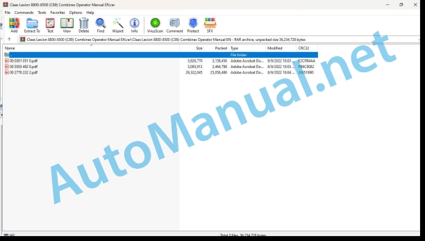
File List:

00 0301 051 0.pdf
00 0303 482 0.pdf
00 2776 222 2.pdf

00 0301 051 0.pdf:

PROFI CAM 3
Table of contents
1 Introduction
1.1 Notes on the manual
1.1.1 Validity of manual
1.1.2 Information about this Operator’s Manual
1.1.3 Symbols and notes
1.1.4 Optional equipment
1.1.5 Qualified specialist workshop
1.1.6 Maintenance information
1.1.7 Warranty notes
1.1.8 Spare parts and technical questions
1.2 Intended use
1.2.1 Intended use
1.2.2 Reasonably foreseeable misuse
2 Safety
2.1 Identifying warnings
2.1.1 Hazard signs
2.1.2 Signal word
2.2 Safety rules
2.2.1 Meaning of Operator’s Manual
2.2.2 Observing safety decals and warnings
2.2.3 Optional equipment and spare parts
3 Product description
3.1 Overview and method of operation
3.1.1 How the PROFI CAM works
3.2 Identification plates and identification number
3.2.1 Position of identification plates
3.2.2 Explanation of PROFI CAM identification plate
3.3 Information on the product
3.3.1 CE marking
4 Operating and control elements
4.1 Camera system
4.1.1 Camera system monitor
4.2 Menu structure
4.2.1 Main menu
4.2.2 menu
4.2.3 menu
4.2.4 menu
4.2.5 menu
4.2.6 menu
5 Technical specifications
5.1 PROFI CAM
5.1.1 Monitor
5.1.2 Camera
5.1.3 Switch box
5.1.4 Degree of protection against foreign bodies and water
6 Preparing the product
6.1 Shutting down and securing the machine
6.1.1 Switching off and securing the machine
6.2 Prior to operation
6.2.1 Carry out prior to operation
6.2.2 Installing the sun protection
6.2.3 Aligning the camera
6.2.4 Connecting the camera electrics
7 Operation
7.1 Monitor
7.1.1 Switching on the monitor
7.1.2 Calling up the menu
7.1.3 Setting a menu item
7.1.4 Setting the image orientation
7.1.5 Setting automatic screen darkening
7.1.6 Image mirroring
7.1.7 Setting the trigger view
7.1.8 Setting the follow-up time for trigger view
7.1.9 Setting the display mode
7.1.10 Activating/deactivating a display mode
8 Faults and remedies
8.1 Electrical and electronic system
8.1.1 Overview of problems on PROFI CAM camera system
8.1.2 Replacing the switch box fuse
9 Maintenance
9.1 Maintenance intervals
9.1.1 Every 10 operating hours or daily
9.2 Camera system
9.2.1 Checking the camera system for dirt
9.2.2 Cleaning the camera
9.2.3 Cleaning the switch box
9.2.4 Cleaning the monitor
10 Placing out of operation and disposal
10.1 General Information
10.1.1 Putting out of operation and disposal
11 Technical terms and abbreviations
11.1 Abbreviations
11.1.1 Units
11.1.2 Abbreviations
11.1.3 Technical terms

00 0303 482 0.pdf:

PROFI CAM 4
Table of contents
1 Introduction
1.1 Notes on the manual
1.1.1 Validity of manual
1.1.2 Information about this Operator’s Manual
1.1.3 Symbols and notes
1.1.4 Optional equipment
1.1.5 Qualified specialist workshop
1.1.6 Maintenance information
1.1.7 Notes on warranty
1.1.8 Spare parts and technical questions
1.2 Intended use
1.2.1 Intended use
1.2.2 Reasonably foreseeable misuse
2 Safety
2.1 Identifying warnings
2.1.1 Hazard signs
2.1.2 Signal word
2.2 Safety rules
2.2.1 Meaning of Operator’s Manual
2.2.2 Structural changes
2.2.3 Optional equipment and spare parts
2.2.4 Operation only following proper putting into operation
2.2.5 Technical status
2.2.6 Respecting technical limit values
Respecting technical limit values
2.2.7 Hazards when driving on roads and fields
3 Product description
3.1 Overview and method of operation
3.1.1 How the PROFI CAM works
3.2 Identification plates and identification number
3.2.1 Identification plates
3.3 Information on the product
3.3.1 CE marking
4 Operating and display elements
4.1 Camera system
4.1.1 Camera system monitor
4.1.2 CEBIS
4.2 Menu structure
4.2.1 Main menu
4.2.2 menu
4.2.3 menu
4.2.4 menu
4.2.5 menu
4.2.6 menu
5 Technical specifications
5.1 PROFI CAM
5.1.1 Monitor
5.1.2 Camera
5.1.3 Switch box
6 Preparing the product
6.1 Switching off and securing the machine
6.1.1 Switching off and securing the machine
6.2 Prior to putting into operation
6.2.1 Carry out prior to operation
6.2.2 Installing the sun protection
6.2.3 Aligning the camera
7 Operation
7.1 Monitor
7.1.1 Switching on the monitor
7.1.2 Calling up the menu
7.1.3 Setting a menu item
7.1.4 Setting the image orientation
7.1.5 Setting automatic screen darkening
7.1.6 Image mirroring
7.1.7 Setting the trigger view
7.1.8 Setting the follow-up time for trigger view
7.1.9 Setting the display mode
7.1.10 Activating/deactivating a display mode
8 Faults and remedies
8.1 Electric and electronic system
8.1.1 Overview of problems on PROFI CAM camera system
9 Maintenance
9.1 Maintenance intervals
9.1.1 Every 10 operating hours or daily
9.2 Camera system
9.2.1 Checking the camera system for dirt
9.2.2 Cleaning the camera
9.2.3 Cleaning the switch box
9.2.4 Cleaning the monitor
10 Putting out of operation and disposal
10.1 General information
10.1.1 Putting out of operation and disposal
11 Technical terms and abbreviations
11.1 Abbreviations
11.1.1 Units
11.1.2 Abbreviations
11.1.3 Technical terms

00 2776 222 2.pdf:

GPS PILOT
Table of contents
1 Introduction
1.1 General information
1.1.1 Validity of Manual
1.1.2 Information about this Operator’s Manual
1.1.3 Symbols and notes
1.1.4 Optional equipment
1.1.5 Qualified specialist workshop
1.1.6 Maintenance notes
1.1.7 Notes regarding warranty
1.1.8 Spare parts and technical questions
1.1.9 Licensing for road traffic
General operating permit
1.1.10 Open Source Software Licenses
1.2 Intended use
1.2.1 Intended use
1.2.2 Reasonably foreseeable misuse
2 Safety
2.1 Identifying warnings
2.1.1 Hazard signs
2.1.2 Signal word
2.2 Safety rules
2.2.1 Importance of Operator’s Manual
2.2.2 Update of terminal software
2.2.3 Requirements made on all persons working with the product
2.2.4 Hazard areas
Hazard areas
2.2.5 Hazard due to restricted view
2.2.6 Interaction between terminal and machine or tractor
2.2.7 Structural changes
2.2.8 Optional equipment and spare parts
2.2.9 Operation only following proper putting into operation
2.2.10 Technical status
2.2.11 Hazard caused by damage to the product
2.2.12 Danger due to incorrect displays
2.2.13 Danger due to map view not having fully loaded
2.2.14 Danger due to limited operability
2.2.15 Respecting technical limit values
2.2.16 Preparing the product for road travel
2.2.17 Hazards when driving on the road with an ISOBUS implement
2.2.18 Hazards when driving on the road and on the field
2.2.19 Potentially fatal electric shock from overhead lines
2.2.20 Maintenance and repair work
2.2.21 Driving with the GPS PILOT
Road travel
Fieldwork
Position of machine and implement
2.2.22 Working with ISOBUS UT, Task Control and Section Control*
2.2.23 Signal tones
2.2.24 Incorrect configuration
3 Product description
3.1 Overview and method of operation
3.1.1 CEMIS 1200 overview
3.1.2 Overview of navigation controller SAT-900
3.1.3 Overview of correction signals
EGNOS / WAAS / MSAS
SATCOR by Trimble RTX
RTK Ready
3.1.4 Overview of UCM (Universal Communication Module)
3.2 Safety devices
3.2.1 Automatic cut-out when the maximum speed is exceeded
3.2.2 Standby mode when the speed falls below the minimum
3.2.3 Manual override
3.3 Optional equipment
3.3.1 SATCOR by Trimble RTX
3.3.2 RTK
3.3.3 RTK bridging/RTK bridging premium
3.3.4 On-the-go maps*
3.3.5 Variable rate application*
3.3.6 Section Control*
3.4 Identification plates and identification numbers
3.4.1 Identification plate of terminal
3.4.2 SAT-900 identification plate
4 Operating and display elements
4.1 CEMIS 1200
4.1.1 Layout conventions of buttons and displays
4.1.2 Operation by touchscreen
4.1.3 Overview of the user interface
Structure of the main menu and function menu
4.1.4 Overview of work phases
4.1.5 work phase
4.1.6 work phase
Comfort keys dialogue
Large comfort key dialogue
Calling up the large comfort keys dialog
4.1.7 Overviews of secondary display areas
Secondary display areas of menu
secondary display area
Secondary display areas of menu
secondary display area
Secondary display areas of menu
4.1.8 Dialogue display
4.1.9 Overview of the status bar
4.1.10 Overview of GNSS status
4.1.11 Fault message and information
4.2 GPS PILOT menu structure
4.2.1 Overview of main menu
4.2.2 main menu item
4.2.3 main menu item
4.2.4 main menu item
4.2.5 main menu item
4.2.6 main menu item
4.2.7 main menu item
4.2.8 main menu item
5 Technical specifications
5.1 GPS PILOT
5.1.1 Correction signal accuracy
5.1.2 CEMIS 1200 specification
5.1.3 Specification of navigation controller SAT-900
6 Preparing the product
6.1 Switching off and securing the machine
6.1.1 Shut down and secure the machine
6.2 Prior to putting into operation
6.2.1 Prior to initial commissioning
6.2.2 Every time before putting into operation
6.3 Putting the vehicle into service
6.3.1 Creating a vehicle
6.3.2 Entering vehicle geometry
6.3.3 Vehicle dimensions of AXION and ARION
6.3.4 Vehicle dimensions of JAGUAR
6.3.5 Vehicle dimensions of LEXION
6.3.6 Vehicle dimensions of TRION
6.3.7 Vehicle dimensions of XERION
6.3.8 Performing steering angle sensor calibration
6.3.9 Carry out rolling angle correction calibration
6.3.10 Reset rolling angle correction
6.4 Putting the implement into service
6.4.1 Creating an implement
6.4.2 Enter implement geometry
6.4.3 Adjusting partial width control
Step 1 of 8, in the field – coverage:
Step 2 of 8, in the field – tolerance:
Step 3 of 8, in the field – offset in the direction of travel (in):
Step 4 of 8, in the field – offset in the direction of travel (out):
Step 5 of 8, field boundaries – coverage:
Step 6 of 8, field boundaries – tolerance:
Step 7 of 8, switching times – switching on:
Step 8 of 8, switching times – switching off:
6.5 Initial putting into operation of correction type
6.5.1 Selecting the correction type
6.5.2 Setting SBAS
6.5.3 Setting SATCOR by Trimble RTX configurations
6.5.4 Setting the RTK Ready configurations
6.5.5 Setting RTK NET configurations
RTK NET login settings
SIM card settings
Switching data connection on or off
Switching the automatic RTK NET connection on or off
Establishing or terminating a connection manually
6.5.6 Setting RTK Bridging configuration
6.6 Activation management
6.6.1 Overview of activations
6.6.2 Transmitting and activating an activation online
6.6.3 Activating a licence with the memory device
6.7 Relocating components
6.7.1 Relocating the terminal to another machine
6.7.2 Relocating SAT-900 to another machine
7 Operation
7.1 Checklists
7.1.1 Preparing field use
7.1.2 Starting fieldwork
7.1.3 Preparing road travel
7.2 CEMIS 1200
7.2.1 Switching on the terminal
Safety information
Confirming safety information
7.2.2 Functions of the setting dialogue
7.2.3 Operating the keyboard and number pad
7.2.4 Operating lists
7.2.5 Connecting a USB memory device to the terminal
7.2.6 Disconnecting a USB memory device from the terminal
7.2.7 Connecting the SD memory card with the terminal
7.2.8 Disconnecting the SD memory card from the terminal
7.2.9 Import and export manager
7.2.10 Switching off the terminal
7.3 System settings
7.3.1 Setting the language
7.3.2 Setting the decimal point.
7.3.3 Setting date and time
7.3.4 Setting the units
7.3.5 Adjusting the display
7.3.6 Setting the volume
7.3.7 Setting the Universal Terminal (UT) number
7.3.8 Setting work phases.
7.3.9 Resetting work phases to factory settings
7.3.10 Configuring the secondary display areas
7.3.11 Setting the main view and additional view
7.4 Map settings
7.4.1 Setting the actual value map
Selecting the actual value map
Setting the actual value map
Colour range
Number of shades
Setting the minimum and maximum values
7.5 Machine settings
7.5.1 Vehicle overview
Vehicle details
7.5.2 Overview of implements
Implement details
7.6 Task Management
7.6.1 Task management functions
7.6.2 Creating a new task
Selecting a field
Creating a new field
Selecting a work step
Selecting a driver
Creating a task
7.6.3 Displaying and editing task details
7.6.4 Starting and pausing a task
Starting a task
Pausing in task
7.6.5 Creating TASKDATA
Editing names
7.6.6 Activating TASKDATA
7.6.7 Deleting TASKDATA
7.6.8 Exporting TASKDATA
7.6.9 Importing TASKDATA
Online file transfer
7.6.10 Creating a field
7.6.11 Editing a field
7.6.12 Selecting a field
7.7 Boundaries
7.7.1 Creating a field boundary
Settings
Selecting the field boundary type
Switching automatic completion on or off
Recording the field boundary
Turning manoeuvre
Completing recording
Approaching the starting point
Setting the end point manually
7.7.2 Overview of field boundaries
Field boundary details
7.7.3 Setting the headland line
7.8 Reference tracks
7.8.1 Overview of types of fieldwork
Straight line tracking / A=B line
Straight line guidance with an angle (A+ angle)
AB contour line guidance
7.8.2 Creating a straight reference track
7.8.3 Creating a straight reference track with
7.8.4 Setting point B again
7.8.5 Creating a straight reference track with an angle
7.8.6 Creating a straight reference track manually
7.8.7 Creating an AB contour reference track
7.8.8 Overview of reference tracks
7.8.9 Reference track details
7.9 Field driving with GPS PILOT
7.9.1 Changing the GPS PILOT over to
master switch
switch
7.9.2 Changing the GPS PILOT over to
master switch
switch
7.9.3 Activating the reference track
7.9.4 Selecting a reference track
7.9.5 Change reference track
Adapting the sequence of reference tracks
Changing by quick access
7.9.6 GPS PILOT activation options
Particularities
7.9.7 Covering a field
7.9.8 GPS PILOT deactivation options
Further switching-off conditions
Seat contact switch
Speed range
GNSS signal
7.9.9 Driving with several machines
7.9.10 Relocating the tracks
7.9.11 Setting the track selection point
7.9.12 Setting the aggressiveness
7.10 Partial width display and partial width control
7.10.1 Section Control*
Working with Section Control
Displaying in field view
Manually override all partial widths or groups
7.11 Rate control
7.11.1 Creating a volume
7.11.2 Overview of quantities
Volume details
7.12 ISOBUS-UT
7.12.1 Loading the ISOBUS operating screen
7.12.2 Selecting an ISOBUS implement
7.12.3 Deleting the ISOBUS operating screen
7.12.4 ISOBUS implement information
7.12.5 Creating an AUX-N assignment
7.12.6 Overview of AUX-N assignments
Deleting an assignment individually
7.12.7 Overview of the ISOBUS control device
7.12.8 Loading AUX-N assignments
8 Faults and remedies
8.1 Faults and solutions
8.1.1 System start
8.1.2 Initial commissioning
8.1.3 Faulty GNSS signal
8.1.4 EGNOS / WAAS / MSAS correction signals
8.1.5 SATCOR correction signal
8.1.6 RTK NET correction signal
8.1.7 Universal Communication Module (UCM) status display
Status LED
Connection status LED
8.1.8 RTK Bridging correction signal
8.1.9 Activating GPS PILOT
8.1.10 Fault during track guidance
8.1.11 ISOBUS-UT
8.2 CEMIS 1200
8.2.1 Creating a screenshot
8.2.2 Exporting screenshots
Export all screenshots
Export individual screenshot
8.2.3 Deleting screenshots
Delete all screenshots
Delete individual screenshot
8.3 Diagnostics
8.3.1 Software versions
8.3.2 Diagnostics
8.3.3 Memory allocation
8.3.4 status
GNSS status
SBAS status
RTK Ready status
RTK NET status
SATCOR status
9 Maintenance
9.1 Maintenance interval overview
9.1.1 Every 10 operating hours or daily
9.1.2 Every 100 operating hours or monthly
9.2 GPS PILOT
9.2.1 Checking the overrider switch
9.2.2 Checking the seat contact switch
10 Putting out of operation and disposal
10.1 General information
10.1.1 Decommissioning and disposal
11 EC declaration of conformity
11.1 GPS PILOT
11.1.1 GPS PILOT EC Declaration of Conformity
11.1.2 EU Declaration of conformity UCM
12 Technical terms and abbreviations
12.1 GPS PILOT
12.1.1 Technical terms
12.1.2 Abbreviations
12.1.3 Units

4.9/5 - (171 votes)
You may also like
John Deere DF Series 150 and 250 Transmissions (ANALOG) Component Technical Manual CTM147 05JUN98

John Deere Repair Technical Manual PDF
John Deere DF Series 150 and 250 Transmissions (ANALOG) Component Technical Manual CTM147 05JUN98

$30.00
Add to cart
John Deere Diesel Engines PowerTech Plus 4.5 L and 6.8 L Base Engine Component Technical Manual CTM206 17DEC09 Portuguese

John Deere Repair Technical Manual PDF
John Deere Diesel Engines PowerTech Plus 4.5 L and 6.8 L Base Engine Component Technical Manual CTM206 17DEC09 Portuguese

$30.00
Add to cart
John Deere PowerTech 4.5L and 6.8L, PowerTech Plus 4.5L and 6.8L Motor base Component Technical Manual CTM107 27 Jan 06 Spanish

John Deere Repair Technical Manual PDF
John Deere PowerTech 4.5L and 6.8L, PowerTech Plus 4.5L and 6.8L Motor base Component Technical Manual CTM107 27 Jan 06 Spanish

$30.00
Add to cart
John Deere POWERTECH E 4.5 and 6.8 L Diesel Engines TECHNICAL MANUAL 25JAN08

John Deere Repair Technical Manual PDF
John Deere POWERTECH E 4.5 and 6.8 L Diesel Engines TECHNICAL MANUAL 25JAN08

$30.00
Add to cart
John Deere Tractors 7500 Parts Catalog CPCQ26568 30 Jan 02 Portuguese

John Deere Parts Catalog PDF

John Deere Tractors 7500 Parts Catalog CPCQ26568 30 Jan 02 Portuguese

$30.00
Add to cart
John Deere Diesel Engines PowerTech 4.5L and 6.8L - Motor Base Technical Manual 07MAY08 Portuguese

John Deere Repair Technical Manual PDF

John Deere Diesel Engines PowerTech 4.5L and 6.8L – Motor Base Technical Manual 07MAY08 Portuguese

$30.00
Add to cart
John Deere Transmission Control Unit Component Technical Manual CTM157 15JUL05

John Deere Repair Technical Manual PDF

John Deere Transmission Control Unit Component Technical Manual CTM157 15JUL05

$30.00
Add to cart
John Deere Harvesters 8500 and 8700 Parts Catalog CPCQ24910 Spanish

John Deere Parts Catalog PDF

John Deere Harvesters 8500 and 8700 Parts Catalog CPCQ24910 Spanish

$30.00
Add to cart
John Deere 6000, 6010 and 6020 Series Tractors Maintenance September 2010

John Deere

John Deere 6000, 6010 and 6020 Series Tractors Maintenance September 2010

$30.00
Add to cart
John Deere Diesel Engines POWERTECH 2.9 L Component Technical Manual CTM126 Spanish

John Deere Repair Technical Manual PDF

John Deere Diesel Engines POWERTECH 2.9 L Component Technical Manual CTM126 Spanish

$30.00
Add to cart
auto manual
    Links of interest
    • About us
    • Refund and Returns Policy
    • Terms & Conditions
    • Shipping Policy
    • Privacy Policy
    • Contact Us
    Product tags
    Agricultural Automotive Crane Forklift Heavy Construction
© All rights reserved. 2023
Copyright 2025 © automanual.net
  • Category
  • Menu
  • About us
  • Shop
  • News
  • Contact Us
  • John Deere
  • Grove
  • Jungheinrich
  • Komatsu
  • Kubota
  • Manitowoc
  • New Holland
  • Yale
  • Yanmar
Login

Lost your password?