Claas Mega 204 203 (935) Combines Operator Manual EN
$50.00
- Model: Mega 204 203 (935) Combines
- Type Of Manual: Operator Manual
- Language: EN
- Format: PDF(s)
- Size: 122 MB
File List:
00 0187 961 0.pdf
00 0293 467 0.pdf
00 0296 902 1.pdf
00 0298 672 0.pdf
00 0301 051 0.pdf
00 0303 482 0.pdf
00 0293 467 0.pdf:
02934670_de.pdf
Instructions for use with CLAAS-Bordinformator
Instructions
Besons on the beach
Kennzeichnung von Warn- und Gefahrenhinweisen
Bestimmungsgeme Verwendung
Functional elements of the Bordinformators
Functions of the Bordinformators on their Program Card
Bordinformator with added programmer card
Bordinformator in Betrieb nehmen
Zugschalter einstellen
Programmieren ohne Programmierkarte
Programmieren mit Programmierkarte
Distanzfaktor
Motoren-Nenndrehzahl
Einstelldaten
Reed contact service an der Vorlegewelle (V)
Induktivgeber an der hinteren Corn-Cracker-Walze (Feldhcksler)
Induktivgeber am Reinigungsgeblse (Mhdrescher)
Induktivgeber am Hauptgetriebe (Feldhcksler)
Messertrommel
Induktivgeber am Motorabtrieb (Feldhcksler)
Induktivgeber am Motorabtrieb (Mhdrescher)
02934670_en.pdf
Operator’s manual CLAAS fieldwork computer
Introduction
Table of contents
Important information
Identification of warning and danger signs
Intended use
Function elements of the fieldwork computer
Functions of the fieldwork computer without programming card
Fieldwork computer with programming card inserted
operating the fieldwork computer
Setting the pull switch
Programming without a programming card
Programming with programming card
Distance factor
Rated engine speed
Setting data
Reed switch on the intermediate drive shaft (V)
Magnetic pickup on the rear corn cracker roller (forage harvester)
Magnetic pickup on the cleaning fan (combine harvester)
Magnetic pickup on the main gearbox (drilling harvester)
Magnetic pickup on threshing drum or cutting cylind
Makup on the engine output (drilling harvester)
Magnetic pickup on the engine output (combine harvester)
02934670_fr.pdf
Instructions for use CLAAS on-board informant
Introduction
Contents
Particularly important
Marking of warnings and dangers
Use in accordance with instructions
Function elements of the on-board informant
On-board informant functions without programming card
On-board informant with programming card in place
Switching on the on-board informant
Adjust barrel draw
Program without a programming card
Program with programming card
Distance factor
Rated engine speed
Setting parameters
Reed pressure switch on the intermediate train (V)
Inductive sensor on the rear roller of the Corn-Cracker (forage harvester)
Inductive sensor on cleaning fan (combine harvester)
Inductive sensor on the main gearbox (forage harvester)
Inductive sensor of the beater or blade holder
Inductive sensor on the motor output (forage harvester)
Inductive sensor on motor output (combine harvester)
02934670_it.pdf
CLAAS bordo computer user manual
Introduction
Important news
Warning and pericolo signal
Specific use
Functional elements of the computer on board
Computer functions on board according to the programming schedule
Computer on board with application programming schedule
Messa in use of the computer on board
Regulation of the switch on the strap
Programming according to the programming schedule
Programming with programming schedule
Fattore di distance
Rated engine speed
Regulatory data
Contact reed of the albero di rinvio (V)
Industrial transmission of the rear corn cracker wheel (trincia foraggi)
Industrial fan transmitter of the power fan (mietitrebbia)
Main transmission driver (trinciaforaggi)
Industrial transmission of the battery or the trinciatura drum
Engine power transmission (trimming)
Engine power transmission (lower speed)
02934670_ru.pdf
Combine serial number
Engine serial number MERCEDES OM 906 LA
Cutterbar identification plate
Identification plate of folding cutterbar
Maize picker head serial number
Multimaster
Serial number of maize head stalk chopper
Straw chopper
Cab serial number
Safety rules
Safety rules
Safety lock
Fire extinguisher
Battery isolating switch
Wheel chock (Not for all countries)
Safety decals with pictorials
Specifications
Conversion factors
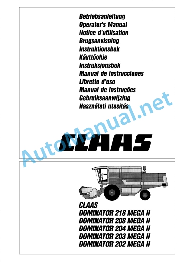
CLAAS DOMINATOR 208 MEGA
CLAAS DOMINATOR 208 MEGA
CLAAS DOMINATOR 208 MEGA
CLAAS DOMINATOR 204 MEGA
CLAAS DOMINATOR 204 MEGA
CLAAS DOMINATOR 204 MEGA
Safety_x0011_features
Front attachments – weights, dimensions
Sectional view of combine
Description and function of the combine
Cutterbar
Threshing mechanism
Straw walkers
Cleaning
Disawning
Basic rules for combining
Prior to operation
Before initial operation
Operator’s platform
Cab with ventilating system
Cab with fan and compressor-type air conditioner
Cab with ventilating system and heating
Reheat System (fogged windows)
Problem, cause and / or remedy – Compressor-type air conditioner
Opening and closing the cabin roof
Opening the cabin roof
Closing the cabin roof
Steering column
Ignition switch
Vehicle information unit
Function of vehicle information unit
Operations display screen
Function of operations display
Switch console
Multi-function lever
Central terminal compartment
Plug-in type module_x0011_(P) CLAAS Autopilot
Grain tank discharge tube – swinging out and in
Grain tank discharge engagement and disengagement_x0004_
Threshing mechanism engagement / disengagement_x0004_
Engaging and disengaging the cutterbar drive
Positioning the cutterbar / maize picker head for road travel
Adjusting the threshing drum speed
Adjusting the steering column position
Driver’s seat, mechanical
Weight adjustment
Height adjustment
Seat angle adjustment
Seat depth adjustment
Lumbar support
Armrest angle
Adjusting the driver’s seat horizontally
Access ladders
Front ladder
Access and ladder extension
Rear ladder
Driving the combine
Engine speed turn switch
Starting the engine
Adjusting stiffness of ground speed control lever
Gear ranges
Stopping the combine
Driving behaviour
Steering
Foot brake
Handbrake
Stopping the engine
CLAAS_x0011_Autopilot
Rear axle
Setting the adjustable rear axle
Changing the rear axle from transport position to working position
CLAAS-4-Trac-System
Towing a combine with driven rear axle
Cutterbar cylinders
Hydraulic cylinders
Attaching the cutter_x0004_bar hydraulic cylinders
Attaching the right-hand cutterbar cylinder
Attaching a third cutterbar cylinder
Towing and side walk railing
Towing the combine
Backward
Side walk railing
Tilting the side walk railing
Cab and lighting
Driving lights, worklights and mirrors
Operation – cutterbar
Attaching the cutterbar
Adjusting the strippers DOMINATOR MEGA 204
Machine with CLAAS Auto Contour
Levelling the coupling lug cylinders
Machine without Auto Contour
Levelling the cutterbar
Connecting the universal drive shafts DOMINATOR 208 MEGA
Connecting the universal drive shafts DOMINATOR 204 MEGA
Connecting hydraulic hoses
Connecting the cables
Installing the stands
Adjustments at the cutterbar
Dividers
Grain lifters
Removing the knife
Installing the knife
Adjusting the height of the knife head
Adjusting the knife clips
Spare knife
Cutterbar skids
Reel tines
Reel drive
Fore and aft reel adjustment (mechanical)
Fore and aft reel adjustment (hydraulic)
Reel variable speed drive
Main table auger
Adjust clearance to cutterbar trough
Adjusting position of auger fingers
Adjusting the stripper plates
Replacing knife sections in the field
Operation – basic machine
Feeder housing
Cutterbar reverse drive
CLAAS Auto Contour Automatic cutting height control and lateral levelling system
Cutterbar automatic pre-set height (machines with Auto Contour)
Adjusting the cutterbar floatation springs
Checking the cutterbar floatation springs and checking the feeder house suspension for smooth mov…
Setting the cutting height indicator
Cutterbar spring pressure indicator
Adjusting the cutterbar drop rate
Putting the CLAAS Auto Contour System into operation
Operation with maize picker head
Programming the CLAAS Auto Contour System
Setting chart for automatic cutting height control
Putting the cutterbar automatic pre-set height system_x0004_ into operation (machines with Auto Contour)
CLAAS Contour System (ground pressure control)
Setting the cutterbar ground pressure
Putting the CLAAS Contour System into operation
CLAAS cutterbar pre-set height
Putting the cutterbar pre-set height system into operation
Cutterbar adjusting range
Clearance height
Cutterbar adjusting range without Auto Contour
Clearance height to underside of cutterbar skid
Cutterbar clutch
Engaging and disengaging the cutterbar
Threshing mechanism
Stone trap
Engaging and disengaging the threshing mechanism
Concave adjustment
Concave settings
Threshing drum
Cleaning dirty threshing parts
Threshing drum speed
Adjusting the threshing drum speed
Threshing drum speed display
Threshing drum two-step variable speed drive
Preconcave
Disawning
Threshing segment
Unslugging the threshing drum
Impeller
Deflector curtain
Straw walkers and cleaning
Straw walkers
Intensive separation system
Cleaning the straw walkers
Straw walker risers
Warning signal
Sieve pan
Preparation floor
Cleaning fan
Electrical fan speed adjustment
Fan speed display
Ventilated straw walker step
Adjusting the butterfly valve
Adjusting the wind board
Adjusting the frogmouth sieves
Hillside riser plates (machines without 3-D cleaning system)
Lower sieves
Removing upper sieves
Installing upper sieves
Removing lower sieves
Installing lower sieves
Tightening torques of the axial bolts for the upper and lower sieves
Dynamic sidehill levelling (3-D cleaning system)
Combine performance monitor
Adjusting monitor to crop type
Adjusting sensitivity of sensors
Grain delivery
Augers and auger troughs
Elevators
Grain tank
Grain tank covers
Unloading the tank
Rear ladder with safety switch
Grain tank discharge auger
Grain tank discharge – engage and disengage
Clean-out door on grain tank discharge tube
Drive to grain tank discharge augers
Shear bolt – grain tank discharge
Lateral auger drive
Grain tank fill indicator
Acoustic grain tank fill indicator
Straw chopper / Chaff spreader
Straw chopper
Before using the straw chopper, check
Putting the straw chopper into operation
Adjusting spreading width
Electric deflector adjustment
Adjusting the deflectors
Adjusting the length of cut
Adjusting cross knife
Putting the straw chopper out of operation and changing over to windrowing straw
Hitching the cutterbar trailer to the combine
Chaff spreader
Setting the chaff spreader
Sieve chart and suggested combine adjustments
Sieve chart
Suggested_x0004_ combine adjustments
Disawner plates
Threshing segment
Problem, cause and / or remedy – Basic machine
Maintenance – basic machine, cutterbar
Important maintenance instructions
Important maintenance instructions and safety_x0011_rules
Maintenance schedules and lubricants charts
Maintenance schedules
Lubricants charts
Hydraulic system
Hydraulic accumulators
Checking the oil level (Hydrostatic ground speed drive and working hydraulics_x0004_)
Changing hydraulic oil (Hydrostatic ground speed drive and working hydraulics_x0004_) Linde HPV 75 and …
Changing the hydraulic oil filter
Refilling the system after hydraulic oil change
Hydrostatic pump adjustment
Bleeding the reel cylinders
Bleeding the hydraulic cylinders for cutterbar lateral levelling (Machines with Auto Contour System)
Foot brake / brake fluid
Transmission and gearboxes
Gear shift control adjustment
Change-speed transmission gearbox
Checking oil level
Oil change
Final drives DOMINATOR 208 MEGA
Checking oil level
Oil change
Final drives DOMINATOR 204 MEGA
Checking oil level
Oil change
Rear wheel drive planetary gears CLAAS 4-Trac System
Check oil level
Oil change
Knife drive casing
Checking the oil level / oil change
Threshing drum reduction gearbox
Checking oil level
Oil change
Grain tank
Angle drive on grain tank discharge auger
Angle drive on grain tank (DOMINATOR 208 MEGA)
Feeder housing
Tension feeder chains
Elevator chains
Tension grain elevator chain
Tension returns elevator chain
Drive belts / drive chains – basic_x0011_machine
General notes
Drive diagram left
Drive diagram right
Drive belts / drive chains
Removing cutterbar drive belt_x0011_(1)
Fitting and tensioning cutterbar drive belt_x0011_(1)
Tensioning compressor drive belt_x0011_(2)
Tensioning hydrostatic ground drive belt_x0011_(3)
Tensioning working hydraulics pump drive belt_x0011_(4)
Removing and installing the power band belt_x0011_(3)
Threshing mechanism drive belt_x0011_(5)
Removing and installing the threshing mechanism drive belt_x0011_(5)
Grain tank unloading drive belt_x0011_(6)
Removing and installing the sieve pan drive belt_x0011_(7)
Removing and fitting fan variable-speed belt_x0011_(8)
Removing and installing the sieve pan drive belt_x0011_(9)
Removing and installing the sieve pan drive belt_x0011_(10)
Removing and installing the straw walker drive belt_x0011_(11)
Removing and installing the intensive separation system drive belt_x0011_(12)
Removing and installing the chaff spreader drive belt_x0011_(15)
Chaff spreader drive belt_x0011_(16)
Straw chopper intermediate drive belt_x0011_(21)
Tensioning suction blower drive belt_x0011_(22)
Removing and fitting threshing drum variable speed drive belt_x0011_(23)
Removing and filtting the threshing drum drive belt_x0011_(24)
Tensioning radiator screen intermediate drive belt_x0011_(27)
Tensioning the grain tank unloading intermediate drive chain_x0011_(31) (DOMINATOR 208 MEGA)
Tensioning the grain tank unloading intermediate drive chain_x0011_(32) (DOMINATOR 208 MEGA)
Tensioning the grain tank unloading intermediate drive chain_x0011_(31) (DOMINATOR 204 MEGA)
Tensioning returns drive chain_x0011_(33)
Removing and installing the accelerator drive belt_x0011_(17)
Straw chopper drive belt_x0011_(20)
Drive belts / drive chains – cutterbar
General notes
Drive diagram cutterbar
Tensioning knife drive belt_x0011_(40)
Tensioning main table auger drive chain_x0011_(41)
Tensioning reel drive chain_x0011_(42)
Removing and fitting reel drive belt_x0011_(43)
Tensioning reel drive chain_x0011_(44)
Tensioning reel drive chain_x0011_(45)
Cab / Compressor-type air condi_x0004_tioner_x0011_
Cleaning the filters
Compressor-type air conditioner
Cleaning the condenser
Checking refrigerant level
Replacing the filter receiver drier
Required refrigerant quantity – Refrigerant_x0011_R_x0011_134_x0011_a
Maintenance work before the harvest
Fire extinguisher
Have fire extinguisher checked for serviceable condition
Checking the speed of the straw walker shaft
Setting the magnetic pick-ups
Machines equipped with fieldwork computer
Straw chopper
Changing the free-swinging knives
Removing knives
Installing knives
Changing the fixed stationary knives
Winter storage instructions for combines
Maintenance – engine
Important maintenance instructions
Important maintenance instructions and safety_x0011_rules
Maintenance schedules and lubricants charts
Maintenance schedule
Lubricants chart
Maintenance – engine
Engine overview
Fuel feed system
Fuel tank
Fuel shut-off tap
Water separator / fuel prefilter (extra equipment – small version)
Fuel prefilter
Water separator / fuel prefilter (extra equipment – large version)
Water separator / fuel prefilter disassembled:
Fuel filter
Bleeding the fuel system
Checking engine oil level
Engine oil change
Draining the old oil
Oil filter
Filling in engine oil
Tensioning the alternator belt
Cooling system
Water drain plugs on the engine block
Water cooler
Filling the cooling system with coolant
Overpressure
Antifreeze / corrosion protection
Warning notice
Cooling water temperature
Radiator chaff screen
Cleaning the radiator chaff screen
Folding up radiator chaff screen
Swinging up the oil cooler
Clean water cooler and intercooler
Dry-type air cleaner
Warning device
Cleaning the air cleaner intake screen
Cleaning the air cleaner
Cleaning the dry-type air cleaner with dust extractor unit
Removing the main filter cartridge
Installing the main filter cartridge
Safety cartridge
Electrical equipment
Alternator
Engine_x0011_problems, cause and / or remedy
Engine winter storage
Engine preservation
Lubrication chart
Lubricants and lubrication instructions
00 0301 051 0.pdf:
PROFI CAM 3
Table of contents
1 Introduction
1.1 Notes on the manual
1.1.1 Validity of manual
1.1.2 Information about this Operator’s Manual
1.1.3 Symbols and notes
1.1.4 Optional equipment
1.1.5 Qualified specialist workshop
1.1.6 Maintenance information
1.1.7 Warranty notes
1.1.8 Spare parts and technical questions
1.2 Intended use
1.2.1 Intended use
1.2.2 Reasonably foreseeable misuse
2 Safety
2.1 Identifying warnings
2.1.1 Hazard signs
2.1.2 Signal word
2.2 Safety rules
2.2.1 Meaning of Operator’s Manual
2.2.2 Observing safety decals and warnings
2.2.3 Optional equipment and spare parts
3 Product description
3.1 Overview and method of operation
3.1.1 How the PROFI CAM works
3.2 Identification plates and identification number
3.2.1 Position of identification plates
3.2.2 Explanation of PROFI CAM identification plate
3.3 Information on the product
3.3.1 CE marking
4 Operating and control elements
4.1 Camera system
4.1.1 Camera system monitor
4.2 Menu structure
4.2.1 Main menu
4.2.2
4.2.3
4.2.4
4.2.5
4.2.6
5 Technical specifications
5.1 PROFI CAM
5.1.1 Monitor
5.1.2 Camera
5.1.3 Switch box
5.1.4 Degree of protection against foreign bodies and water
6 Preparing the product
6.1 Shutting down and securing the machine
6.1.1 Switching off and securing the machine
6.2 Prior to operation
6.2.1 Carry out prior to operation
6.2.2 Installing the sun protection
6.2.3 Aligning the camera
6.2.4 Connecting the camera electrics
7 Operation
7.1 Monitor
7.1.1 Switching on the monitor
7.1.2 Calling up the menu
7.1.3 Setting a menu item
7.1.4 Setting the image orientation
7.1.5 Setting automatic screen darkening
7.1.6 Image mirroring
7.1.7 Setting the trigger view
7.1.8 Setting the follow-up time for trigger view
7.1.9 Setting the display mode
7.1.10 Activating/deactivating a display mode
8 Faults and remedies
8.1 Electrical and electronic system
8.1.1 Overview of problems on PROFI CAM camera system
8.1.2 Replacing the switch box fuse
9 Maintenance
9.1 Maintenance intervals
9.1.1 Every 10 operating hours or daily
9.2 Camera system
9.2.1 Checking the camera system for dirt
9.2.2 Cleaning the camera
9.2.3 Cleaning the switch box
9.2.4 Cleaning the monitor
10 Placing out of operation and disposal
10.1 General Information
10.1.1 Putting out of operation and disposal
11 Technical terms and abbreviations
11.1 Abbreviations
11.1.1 Units
11.1.2 Abbreviations
11.1.3 Technical terms
00 0303 482 0.pdf:
PROFI CAM 4
Table of contents
1 Introduction
1.1 Notes on the manual
1.1.1 Validity of manual
1.1.2 Information about this Operator’s Manual
1.1.3 Symbols and notes
1.1.4 Optional equipment
1.1.5 Qualified specialist workshop
1.1.6 Maintenance information
1.1.7 Notes on warranty
1.1.8 Spare parts and technical questions
1.2 Intended use
1.2.1 Intended use
1.2.2 Reasonably foreseeable misuse
2 Safety
2.1 Identifying warnings
2.1.1 Hazard signs
2.1.2 Signal word
2.2 Safety rules
2.2.1 Meaning of Operator’s Manual
2.2.2 Structural changes
2.2.3 Optional equipment and spare parts
2.2.4 Operation only following proper putting into operation
2.2.5 Technical status
2.2.6 Respecting technical limit values
Respecting technical limit values
2.2.7 Hazards when driving on roads and fields
3 Product description
3.1 Overview and method of operation
3.1.1 How the PROFI CAM works
3.2 Identification plates and identification number
3.2.1 Identification plates
3.3 Information on the product
3.3.1 CE marking
4 Operating and display elements
4.1 Camera system
4.1.1 Camera system monitor
4.1.2 CEBIS
4.2 Menu structure
4.2.1 Main menu
4.2.2
4.2.3
4.2.4
4.2.5
4.2.6
5 Technical specifications
5.1 PROFI CAM
5.1.1 Monitor
5.1.2 Camera
5.1.3 Switch box
6 Preparing the product
6.1 Switching off and securing the machine
6.1.1 Switching off and securing the machine
6.2 Prior to putting into operation
6.2.1 Carry out prior to operation
6.2.2 Installing the sun protection
6.2.3 Aligning the camera
7 Operation
7.1 Monitor
7.1.1 Switching on the monitor
7.1.2 Calling up the menu
7.1.3 Setting a menu item
7.1.4 Setting the image orientation
7.1.5 Setting automatic screen darkening
7.1.6 Image mirroring
7.1.7 Setting the trigger view
7.1.8 Setting the follow-up time for trigger view
7.1.9 Setting the display mode
7.1.10 Activating/deactivating a display mode
8 Faults and remedies
8.1 Electric and electronic system
8.1.1 Overview of problems on PROFI CAM camera system
9 Maintenance
9.1 Maintenance intervals
9.1.1 Every 10 operating hours or daily
9.2 Camera system
9.2.1 Checking the camera system for dirt
9.2.2 Cleaning the camera
9.2.3 Cleaning the switch box
9.2.4 Cleaning the monitor
10 Putting out of operation and disposal
10.1 General information
10.1.1 Putting out of operation and disposal
11 Technical terms and abbreviations
11.1 Abbreviations
11.1.1 Units
11.1.2 Abbreviations
11.1.3 Technical terms
John Deere Parts Catalog PDF
John Deere Harvesters 8500 and 8700 Parts Catalog CPCQ24910 Spanish
John Deere Repair Technical Manual PDF
John Deere Parts Catalog PDF
John Deere Tractors 6300, 6500, and 6600 Parts Catalog CQ26564 (29SET05) Portuguese
John Deere Repair Technical Manual PDF
John Deere Repair Technical Manual PDF
John Deere 18-Speed PST Repair Manual Component Technical Manual CTM168 10DEC07
John Deere Repair Technical Manual PDF
John Deere POWERTECH E 4.5 and 6.8 L Diesel Engines TECHNICAL MANUAL 25JAN08
John Deere Repair Technical Manual PDF
John Deere Repair Technical Manual PDF
John Deere Repair Technical Manual PDF

