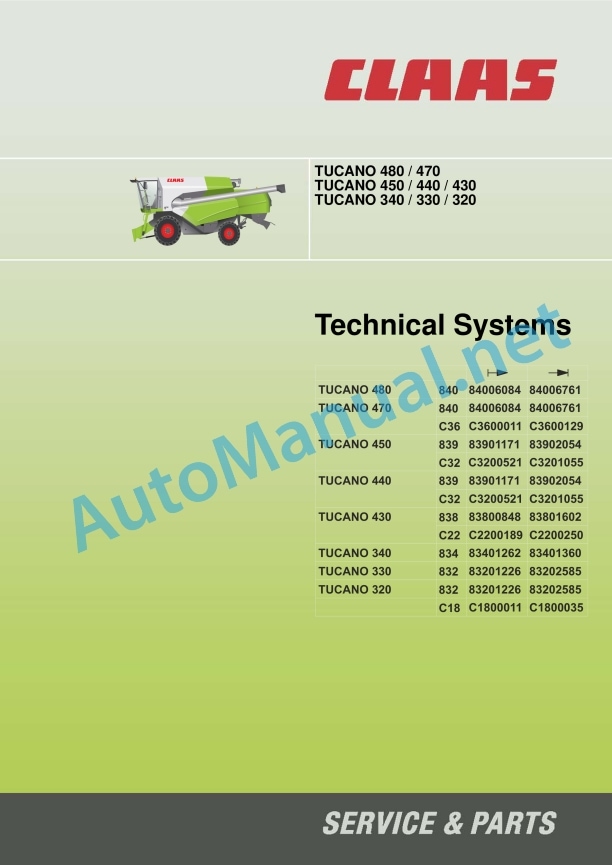
Claas Tucano 430 (C22) Combines Technical System EN
$300.00
- Model: Tucano 430 (C22) Combines
- Type Of Manual: Technical System
- Language: EN
- Format: PDF(s)
- Size: 125 MB
File List:
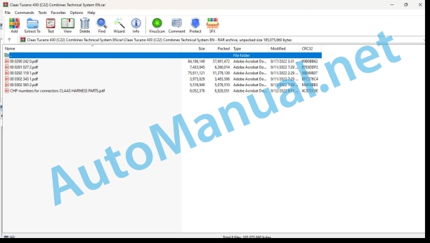
00 0290 242 0.pdf
00 0291 027 2.pdf
00 0292 119 1.pdf
00 0302 343 1.pdf
00 0302 565 2.pdf
CHP-numbers for connectors CLAAS HARNESS PARTS.pdf
00 0290 242 0.pdf:
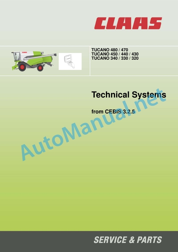
TUCANO 480 / 470
TUCANO 450 / 440 / 430
TUCANO 340 / 330 / 320
Table of contents
CCN explanation
CCN (CLAAS Component Number)
Electric system standard
Overview
Hydraulic system standard
Overview
CCN (CLAAS Component Number)
CCN Index
Introduction
General instructions
Important safety and hazard information
Validity of manual
01 Engine
0125 Injection – / Fuel system
Fuel system
Measured values table
Description of function
0150 Engine attachment parts
Starting the diesel engine, diesel engine speed adjustment – Caterpillar (CAT)
Measured values table
Description of function
Caterpillar speed table
Starting the diesel engine, diesel engine speed adjustment – Daimler (MTU)
Measured values table
Description of function
Daimler speed table
0155 Engine control
Diesel engine monitoring – Caterpillar (CAT)
Measured values table
Description of function
Diesel engine fault code – J 1939 / Engine diagnosis / Component position – CAT
Diesel engine monitoring – Daimler (MTU)
Measured values table
Description of function
Diesel engine fault code – J 1939 / Engine diagnosis / Position of components – Daimler (MTU)
0165 Exhaust gas treatment
Compressed air system MTU TIER 4i
Description of function
SCR system – urea heater and injection
Description of function
Combined filling level / urea temperature sensor
Description of function
Urea pump unit
Description of function
Reduction catalyst temperature sensors
Description of function
Dosing unit
Description of function
NOx sensor
Description of function
Combined intake air moisture and temperature sensor
Description of function
03 Chassis
0330 Driven steering axle, rear
Measured values table
Description of function
4-Trac hydraulic circuit diagram
0335 Ground drive
Hydrostatic ground drive
Function overview graphic / CAT diesel engine
Function overview graphic / Daimler diesel engine
Description of function
Wiring diagram
Pump unit (HPV)
Description of function
Servo-control valve
Description of function
Multifunction valve (7013/7014)
Description of function
Ground drive fixed-displacement motor (HMF)
Description of function
Testing – measuring
04 Brake
0405 Service brake
Brake hydraulics circuit diagram
05 Steering
0505 Steering
Steering system
Neutral function diagram
Steering-actuated function diagram
Checking the steering system
Description of function
0510 Automatic steering
AUTOPILOT / Sensing system
Measured values table
Description of function
Checking the AUTOPILOT system
AUTOPILOT / LASER PILOT
Measured values table
Description of function
Checking the AUTOPILOT system
Basic machine GPS steering system
Measured values table
Description of function
Checking the AUTOPILOT system
EGNOS GPS steering system
Description of function
OMNISTAR HP GPS steering system
Description of function
RTK GPS steering system
Description of function
GPS Pilot with RTK
RTK NET GPS steering system
Description of function
BASELINE HD GPS steering system
Description of function
09 Hydraulic system
0920 Valves
Main valve
Description of function
AUTOCONTOUR / reversing valve block
Front attachment dampening valve block
Steering (Orbitrol) valve block
Autopilot valve block
Description of function
Low-pressure hydraulic system valve block
Low-pressure hydraulic system valve block
Low-pressure hydraulic system valve block (left chopper drive, type 83x)
Description of function
Reel drive valve block
Grain tank unloading tube valve block
Threshing drum variable-speed drive valve block
0980 Hydraulic circuit diagram
Vehicle hydraulic system circuit diagrams
Working hydraulics, steering hydraulics
Testing the working hydraulics
Low-pressure hydraulic system circuit diagram, hydraulic reel drive type – 83x
Testing the low-pressure hydraulic system and the reel drive
Low-pressure hydraulic system circuit diagram, hydraulic reel drive – type 840
Testing the low-pressure hydraulic system and the reel drive
Hydrostatic ground drive (type 832 – 839)
Hydrostatic ground drive (type 840)
Brake hydraulics circuit diagram
Front attachment hydraulics circuit diagrams
Cutterbar C370-C490 (type 527)
VARIO cutterbar V540-V900 (type 716)
Rape cutter – Drive / VARIO cutterbar V540-V1050 (type 716)
Folding cutterbar 450-540 (type 713)
Conspeed 6-row
Conspeed 8-row
Sunspeed (type 443) hydraulic circuit diagram
10 Electrical / Electronic equipment
1010 Central electrics
Basis of central terminal compartment
Fuse assignment
Relay assignment
Connector designations
Roof central terminal compartment
Fuse assignment
Relay assignment
Connector designations
Patch field
Key to diagram
1012 Modules / sensors
Module overview
Installation position of modules
Module A006 – Automatic air conditioner (ACM)
Key to diagram
Module A007 – Cab fan (CFC)
Key to diagram
Module A009 – AUTOPILOT (ATP)
Key to diagram
Module A015 – Engine control (ECM) – CATERPILLAR (CAT C13, C9)
Key to diagram
Module A015 – electronic engine control (ECM) – Daimler (OM 906, OM 926 TIER 3)
Key to diagram
Module A015 – electronic engine control (ECM) – Daimler (OM 906, OM 926 TIER 4i)
Key to diagram
Module A017 – Engine adaption (ADM) – Daimler (OM 906, OM 926 TIER 3)
Key to diagram
Module A017 – Engine adaption (ADM) – Daimler (OM 906, OM 926 TIER 4i)
Key to diagram
Module A021 – Yield measuring (YMM)
Key to diagram
Module A025 – Sieve adjustment (SAM)
Key to diagram
Module A026 – Deflector adjustment (DAM)
Key to diagram
Module A027 – VARIO cutterbar (VAR)
Key to diagram
Module A032 – Reduction catalyst (SCR) – Daimler (OM 926)
Key to diagram
Module A069 – Vehicle base module (VBM)
Module A069 – Vehicle base module (VBM – 1/3) – Sensors part 1
Module A069 – Vehicle base module (VBM- 2/3) – Sensors part 2
Module A069 – Vehicle base module (VBM- 3/3) – Actuators
Key to diagram A069
Module A075 – Operating panel (OPM)
Key to diagram
Module A130 – Front attachment
Key to diagram
Module A137 – AUTOCONTOUR multisensor
Key to diagram
1015 Wiring harnesses
Wiring looms
Front attachment multicoupler connection
Description of function
Rear drive axle wiring loom
Autopilot wiring loom (cab)
Autopilot wiring loom (rear drive axle)
Trailer hitch wiring loom
Earth wiring loom
Axle wiring loom
Main wiring loom, left
Main wiring loom, right
Engine wiring loom
Rear hood / rotor wiring loom
Rear hood / straw walker wiring loom
Dashboard wiring loom
Operator’s platform lighting wiring loom
Earth / roof central terminal compartment wiring loom
Cab B-column wiring loom
Cab, Vehicle Base Module wiring loom
Cab, lighting wiring loom
Cab, front operating panel wiring loom
Cab, rear control panel wiring loom
Steering column wiring loom
Multicoupler wiring loom
Yield measuring wiring loom
Inclination sensor wiring loom
Heater / ventilation wiring loom
Feed rake conveyor wiring loom
RIO wiring loom – module extension
Deflector plate adjustment wiring loom
Chopper (straw walker) wiring loom
Chopper (rotor) wiring loom
Tine spreader wiring loom
Chaff spreader wiring loom
1035 Operation / Multifunction control lever
T signal function
Measured values table
Description of function
Road travel – fieldwork function
Description of function
1040 Yield measuring
Yield measuring
Description of function
1080 Electronic circuit diagram
Introduction into circuit diagrams
Overview of designations
CLAAS cable marking
Wire colours
Overview of CAN Bus system
Machine circuit diagrams
SCM 01 – Multicoupler
SCM 02a – Power supply / Starting the diesel engine (12 Volt) – Applies to: CAT
SCM 02a – Power supply / Starting the diesel engine (12 Volt) – Applies to: MTU TIER 3
SCM 03a – Battery earth (12 Volt) – MTU TIER 3 – CAT TIER 3
SCM 03b – Power supply / Starting the diesel engine (24 Volt) – MTU TIER 4i
SCM 04 – Road travel – Applies to: All types
SCM 05a – Power supply of modules I – Applies to: CAT TIER 3
SCM 05b – Power supply of modules I – Applies to: MTU TIER 3
SCM 05c – Power supply of modules I – Applies to: MTU TIER 4i
SCM 06 – Power supply of modules
SCM 08 – Power supply of sensors – Applies to: All types
SCM 09a – Engine monitoring, speed regulation – Applies to: Caterpillar TIER 3
SCM 09b – Engine monitoring, speed regulation – Applies to: MTU TIER 3
SCM 09c – Engine monitoring, speed regulation – Applies to: MTU TIER 4i
SCM 10a – CAN0 (vehicle CAN) part 1 – Applies to: All types
SCM 10b – CAN0 (vehicle CAN) part 1 – With yield measuring – Applies to: All types
SCM 11 – CAN0 (vehicle CAN) part 2 – Applies to: All types
SCM 12a – CAN1 (J1939 CAN) – Applies to: CAT TIER 3
SCM 12b – CAN1 (J1939 CAN) – Applies to: CAT TIER 3, with yield measuring
SCM 12c – CAN1 (J1939 CAN) – Applies to: MTU TIER 3
SCM 12d – CAN1 (J1939 CAN) – Applies to: MTU TIER 3, with yield measuring
SCM 12e – CAN1 (J1939 CAN) – Applies to: MTU TIER 4i
SCM 12f – CAN1 (J1939 CAN) – Applies to: MTU TIER 4i, with yield measuring
SCM 13 – CAN2 (Front CAN)
SCM 14 – Threshing mechanism
SCM 15 – Engaging the front attachment clutch, reversing
SCM 16a – Machine monitoring – Applies to: Rotor machines
SCM 16b – Machine monitoring – Applies to: Straw walker machines
SCM 17 – Master valve, hydraulic system monitoring
SCM 18 – Ground drive – Applies to: All types
SCM 19a – Air conditioner
SCM 19b – Automatic air conditioner
SCM 20 – Threshing drum speed
SCM 21 – Fan speed
SCM 22 – Throughput monitoring
SCM 23a – Straw chopper – Hydraulic without tine spreader
SCM 23b – Straw chopper – Hydraulic with tine spreader
SCM 23c – Straw chopper – Mechanical without tine spreader
SCM 23d – Straw chopper – Mechanical with tine spreader
SCM 24 – Raise / lower front attachment – AUTO CONTOUR
SCM 25 – Reel adjustment
SCM 26 – Grain tank unloading
SCM 27 – Grain tank full indicator, warning beacons
SCM 28 – 4-Trac – Applies to: All types
SCM 29 – Brake system – Applies to: All types
SCM 30 – Folding the front attachment
SCM 31 – Rape cutter – Applies to: All types
SCM 32 – AUTOLPILOT – Applies to: All types
SCM 33 – Windscreen wiper/washer, horn
SCM 34 – Turn indicator system
SCM 35 – Main lighting circuit, side light
SCM 36 – Drive lights
SCM 37 – Instrument panel illumination – Applies to: All types
SCM 38 – Maintenance light
SCM 39 – Sidefinder
SCM 40a – Work lights main circuit
SCM 40b – Work lights main circuit with Xenon
SCM 41 – Grain tank, returns, sieve pan work lights
SCM 42 – Cab equipment – Applies to: All types
SCM 43 – Mirror adjustment
SCM 44 – Service sockets
SCM 45 – Table adjustment
SCM 46 – Sieve adjustment
SCM 47a – Deflector plate adjustment, straw chopper
SCM 47b – Deflector plate adjustment, Special Cut straw chopper
SCM 48 – Options
SCM 50 – Yield measuring
SCM 51 – T signal
SCM 52 – Rear-mounted camera
SCM 53 – Urea injection
SCM 54a CAN3 (Steering CAN) GPS Pilot BASIC
SCM 54b CAN3 (Steering CAN) GPS Pilot II
SCM 54c CAN3 (Steering CAN) GPS Pilot II with RTK
SCM 54d CAN3 (Steering CAN) GPS Pilot II with RTK NET
SCM 55a – Oveview of modules I CAT and MTU TIER3
SCM 55b – Overview of modules I MTU TIER4i
SCM 56a – Overview of modules II CAT TIER3
SCM 56b – Overview of modules II MTU TIER3
SCM 56c – Overview of modules II MTU TIER4i
SCM 57 – Overview of connectors
SCM 58 – Earth supply – Applies to: All types
Front attachment circuit diagrams – Soybean cutterbar (type 438)
T438 01 – Multicoupler
T438 02 – Reel
T438 03 – Autocontour
T438 04 – Lighting
T438 05 – AUTOPILOT
Front attachment circuit diagrams – Sirius – Flexhead – Cutterbar (type 441)
T441 01 – Multicoupler
T441 02 – Reel
T441 03 – Cutting table adjustment
T441 04 – Autocontour
T441 05 – Lighting
T441 06 – AUTOPILOT
Front attachment circuit diagrams – Sirius – Rigidhead – Cutterbar (type 442)
T442 01 – Multicoupler
T442 02 – Reel
T442 03 – Autocontour
T442 04 – Lighting
T442 05 – AUTOPILOT
Front attachment circuit diagrams – Standard – Cutterbar (type 527)
T527 01 – Multicoupler
T527 02 – Reel
T527 03 – Autocontour
T527 04 – AUTOPILOT
Front attachment circuit diagrams – VARIO – Cutterbar (type 529)
T529 01 – Multicoupler
T529 02 – Power supply of modules / CAN Bus
T529 03 – Reel
T529 04 – Cutting table adjustment
T529 05 – Rape cutter
T529 06 – Autocontour
T529 07 – AUTOPILOT
T529 08 – Flashlights
T529 09 – Overview of modules
Front attachment circuit diagrams – rigid cutterbar (type 529)
T529 01 – Multicoupler
T529 02 – Reel
T529 03 – Autocontour
T529 04 – AUTOPILOT
T529 05 – Flashlights
Front attachment circuit diagrams – Flexhead (type 531)
T531 01 – Multicoupler
T531 02 – Power supply of modules / CAN Bus
T531 03 – Reel
T531 04 – Cutting table adjustment
T531 05 – Rape cutter
T531 06 – Autocontour
T531 07 – AUTOPILOT
T531 08 – Flashlights
Front attachment circuit diagrams – MAXFLO (type 537, 538)
T537 T538 01 – Multicoupler
T537, T538 02 – Power supply of modules / CAN Bus
T537, T538 03 – Reel
T537, T538 04 – Cutting table adjustment
T537, T538 05 – Rape cutter
T537, T538 06 – Autocontour
T537, T538 07 – AUTOPILOT
T537, T538 08 – Flashing position light
T537, T538 09 – Overview of modules
Front attachment circuit diagrams – Folding cutterbar (type 713)
T713 01 – Multicoupler
T713 02 – Reel
T713 03 – Folding the front attachment
T713 04 – Autocontour
T713 05 – Lighting
T713 06 – AUTOPILOT
Front attachment circuit diagrams – Standard – Cutterbar (type 715)
T715 01 – Multicoupler
T715 02 – Reel
T715 03 – Rape cutter
T715 04 – Autocontour
T715 05 – AUTOPILOT
Front attachment circuit diagrams – VARIO – Cutterbar (type 716)
T716 00 – Overview of modules
T716 01 – Multicoupler
T716 02 – Power supply of modules / CAN Bus
T716 03 – Reel
T716 04 – Cutting table adjustment
T716 05 – Rape cutter
T716 06 – Autocontour
T716 07 – AUTOPILOT
Circuit diagrams of CONSPEED (types 907, 908, I00, I01)
T907, T908, TI00, TI01 – Multicoupler
T907, T908, TI00, TI01 – Snapper plates
T907, T908, TI00, TI01 – AUTO CONTOUR
T907, T908, TI00, TI01 – Lighting
T907, T908, TI00, TI01 – AUTOPILOT
Front attachment circuit diagrams – Sunspeed (type 443)
T443 01 – Multicoupler
T443 02 – Reel
1081 Overview of Connectors
Connector database (CHP CLAAS)
Example of representation of key numbers (CHP)
Connector representation (CHP)
1085 Networks
BUS systems (CAN) – Basic machine
Description of function
BUS systems (CAN) – Front attachment
Description of function
12 Cab / Operator’s platform
1230 Seat
Seat contact
Measured values table
Description of function
1240 Air condition
Air conditioner function
Measured values table
Description of function
Test menu:
Controls
Test menu operation
Test menu access
Menu item 1
Menu item 2
Menu item 3
Menu item 4
Menu item 5
Menu item 6
Menu item 7
Menu item 8
Menu item 9
Menu item 10
Menu item 11
Menu item 12
20 Crop feeding
2002 Front attachment
Raise / lower front attachment
Measured values table
Description of function
Main valve
Description of function
Front attachment ON / OFF
Measured values table
Description of function
Front attachment reversing
Measured values table
Description of function
Front attachment dampening
Measured values table
Description of function
Front attachment dampening valve
Accumulator pressure filling instructions
Manual cross levelling
Measured values table
Description of function
AUTOCONTOUR / reversing valve block
2010 Cutterbar table
VARIO cutting table adjustment
Measured values table
Reel adjustment function description
2015 Reel / Crop guard
Raise / lower reel, automatic reel height adjustment
Measured values table
Reel adjustment function description
Horizontal reel adjustment
Measured values table
Reel adjustment function description
Reel speed adjustment, automatic reel speed
Measured values table
Reel adjustment function description
26 Ground guidance
2605 Auto-Contour
AUTOCONTOUR (CAC)/Contour
Measured values table
Description of function
AUTOCONTOUR / reversing valve block
Accumulator pressure filling instructions
41 Threshing mechanism
4100 Threshing mechanism
Engaging the threshing mechanism
Measured values table
Description of function
4120 Threshing drum
Threshing drum speed adjustment
Measured values table
Description of function
43 Cleaning system
4320 Sieves / Sieve pan
Sieve adjustment – Upper sieve
Measured values table
Description of function
Sieve adjustment – Lower sieve
Measured values table
Description of function
4325 Cleaning fan
Fan speed adjustment
Measured values table
Description of function
60 Crop discharge / straw discharge
6010 Straw chopper
Chopping / swath discharge (left chopper drive, type 83x)
Measured values table
Description of function
Deflector adjustment
Measured values table
Description of function
61 Grain delivery
6120 Grain tank unloading
Swinging the grain tank unloading tube
Measured values table
Description of function
Grain tank unloading
Measured values table
Description of function
Diagnosis by fault codes
FMI failure code (Failure Mode Indicator)
FMI failure code (Failure Mode Indicator)
FMI 00 (Signal too high)
FMI 01 (Signal too low)
FMI 02 (Erratic signal)
FMI 03 (Voltage too high)
FMI 04 (Voltage too low)
FMI 05 (Current too low)
FMI 06 (Current too high)
FMI 07 (Mechanical failure)
FMI 08 (Abnormal frequency signal)
FMI 09 (Communication error)
FMI 10 (Rate of signal change too fast)
FMI 11 (multiple faults)
FMI 12 (ECU defective)
FMI 13 (Signal outside of calibration range)
FMI 16 (Parameter not available)
FMI 17 (ECU not responding)
FMI 18 (Power supply failure)
FMI 19 (Software conditions not met)
FMI 95 (no signal change)
FMI 96 (CAN Bus system defective)
FMI 97 (Erratic condition)
FMI 98 (Warning)
FMI 99 (Info)
Machine fault code
Machine fault code list (DTC)
Diesel engine fault code
Diesel engine fault code list (SPN)
Position of components
Hydraulic system
Main assembly groups (I to XI)
1001- 1999 Oil reservoir / filter / oil cooler
2001- 2999 Pump / motor
3001- 3999 Hydraulic cylinder
4001- 4999 Restrictor / orifice plate
5001- 5999 Accumulator
6001- 6999 Valve, mechanically actuated
7001- 7999 Valve, hydraulically actuated
8001- 8999 Couplings / connections
9001- 9999 Measuring point / indicating instrument
Electric system
A Terminal / modules
B Sensors
C Electrical / electronic devices
E Lighting
G Voltage sources
H Signal devices / light
K Relays
M Motor (electric)
R Potentiometer / resistor
S Switch / pushbutton – Cab operation
U Switch – External operation
V Electronic components
Y Solenoid coil
Z Actual value switch
Earth points
Central terminal compartment
00 0291 027 2.pdf:
MB OM460LAMB OM502LAMB OM906LAMB OM926LA
Table of contents
CCN explanation
CCN (CLAAS Component Number)
Electric systems standard
Overview
Hydraulic system standard
Overview
CCN (CLAAS Component Number)
Introduction
Safety rules
Safety and hazard precautions
Validity of manual
Validity of manual
01 Engine
0125 Injection / Fuel system
Injection / fuel system PLD
PLD injection system
Description of function
Pumping phases of plug-on pump
Description of function
Control of plug-on pump
Description of function
Classification of plug-on pumps
Example of a plug-on pump identification plate
Elements in example of plug-on pump identification plate
Fuel low-pressure measurement
Special tool
Preparation of fuel low-pressure measurement
Description of function
Measuring values, fuel low-pressure (downstream of fuel filter)
0155 Engine control
Diesel engine monitoring, diesel engine (MB TIER 3) TUCANO, JAGUAR
Measured values table
Description of function
Diesel engine monitoring, diesel engine (MB TIER 3) LEXION
Measured values table
Description of function
Diesel engine monitoring, diesel engine (MB TIER 4i) TUCANO, JAGUAR
Measured values table
Description of function
Limitation of torque in case of lack of urea
Description of function
Limitation of torque in case of insufficient urea quality
Description of function
Torque limitation after exceeding the time with system faults
Description of function
Diesel engine monitoring, diesel engine (MB TIER 4i) LEXION
Measured values table
Description of function
Limitation of torque in case of lack of urea
Description of function
Limitation of torque in case of insufficient urea quality
Description of function
Torque limitation after exceeding the time with system faults
Description of function
0165 Exhaust gas aftertreatment
Compressed-air system of MB TIER 4i (LEXION, TUCANO)
Description of function
Air dryer with integrated pressure controller
Description of function
Compressed air system MB TIER 4i (JAGUAR)
Description of function
Air dryer with integrated pressure controller
Description of function
SCR system – Urea heating and injection
Description of function
Combined filling level / urea temperature sensor
Description of function
Urea pump unit
Description of function
Reduction catalyst temperature sensors
Description of function
Dosing unit
Description of function
NOx sensor
Description of function
Combined intake air humidity and temperature sensor
Description of function
10 Electrical / Electronic equipment
1012 Modules / sensors
Module overview – MB (OM460LA, 502LA, 906LA, 926LA)
Key to diagram
Module A015 – Electronic engine control (ECM) – MB TIER 4i
Connector X1
Key to diagram
Module pin assignment, connector X1
Connector X2, sheet 1 of 2, 6-cylinder inline and V8 engine
Module pin assignment, connector X2 sheet 1 of 2
Connector X2, sheet 2 of 2, 6-cylinder inline engine
Module pin assignment, connector X2 sheet 2 of 2, 6-cylinder inline engine
Connector X2, sheet 2 of 2, V8 engine
Module pin assignment, connector X2 sheet 2 of 2, V8 engine
Module A017 – Engine adaptation module (ADM) – MB TIER 3
Key to diagram
Key to diagram
Module A017 – Engine adaptation module (ADM) – MB TIER 4i
Key to diagram
Key to diagram
Module A032 – Reduction catalyst (SCR) – MB TIER4i
Key to diagram
Key to diagram
Sensors MB OM460LA
Figure of sensors
Sensors on MB 502LA
Figure of sensors
Sensors on MB OM 906LA, OM 926LA
Figure of sensors
1085 Networks
BUS system (CAN) – engine and machine
Description of function
92 Diagnosis
Diagnosis by fault codes
9220 Error codes engine (J1939)
FMI failure code (Failure Mode Indicator)
FMI failure code (Failure Mode Indicator)
FMI 00 (Signal too high)
FMI 01 (Signal too low)
FMI 02 (Erratic signal)
FMI 03 (Voltage too high)
FMI 04 (Voltage too low)
FMI 05 (Current too low)
FMI 06 (Current too high)
FMI 07 (Mechanical failure)
FMI 08 (Abnormal frequency signal)
FMI 09 (Communication error)
FMI 10 (Rate of signal change too fast)
FMI 11 (multiple faults)
FMI 12 (ECU defective)
FMI 13 (Signal outside of calibration range)
FMI 16 (Parameter not available)
FMI 17 (ECU not responding)
FMI 18 (Power supply failure)
FMI 19 (Software conditions not met)
FMI 95 (no signal change)
FMI 96 (CAN Bus system defective)
FMI 97 (Erratic condition)
FMI 98 (Warning)
FMI 99 (Info)
Fault codes
Diesel engine J1939 (MB) fault code list
Description of function
00 0292 119 1.pdf:
TUCANO 480 / 470
TUCANO 450 / 440 / 430
TUCANO 340 / 330 / 320
Table of contents
CCN explanation
CCN (CLAAS Component Number)
Electric system standard
Overview
Hydraulic system standard
Overview
CCN (CLAAS Component Number)
CCN Index
Introduction
General instructions
Important safety and hazard information
Validity of manual
01 Engine
0125 Injection – / Fuel system
Fuel system
Measured values table
Description of function
0150 Engine attachment parts
Starting the diesel engine, diesel engine speed adjustment – Caterpillar (CAT)
Measured values table
Description of function
Caterpillar speed table
Starting the diesel engine, diesel engine speed adjustment – Daimler (MTU)
Measured values table
Description of function
Daimler speed table
0155 Engine control
Diesel engine monitoring – Caterpillar (CAT)
Measured values table
Description of function
Diesel engine fault code – J 1939 / Engine diagnosis / Component position – CAT
Diesel engine monitoring – Daimler (MTU)
Measured values table
Description of function
Diesel engine fault code – J 1939 / Engine diagnosis / Position of components – Daimler (MTU)
0165 Exhaust gas treatment
Compressed air system MTU TIER 4i
Description of function
SCR system – urea heater and injection
Description of function
Combined filling level / urea temperature sensor
Description of function
Urea pump unit
Description of function
Reduction catalyst temperature sensors
Description of function
Dosing unit
Description of function
NOx sensor
Description of function
Combined intake air moisture and temperature sensor
Description of function
03 Chassis
0330 Driven steering axle, rear
Measured values table
Description of function
4-Trac hydraulic circuit diagram
0335 Ground drive
Hydrostatic ground drive
Function overview graphic / CAT diesel engine
Function overview graphic / Daimler diesel engine
Description of function
Wiring diagram
Pump unit (HPV)
Description of function
Servo-control valve
Description of function
Multifunction valve (7013/7014)
Description of function
Ground drive fixed-displacement motor (HMF)
Description of function
Testing – measuring
04 Brake
0405 Service brake
Brake hydraulics circuit diagram
05 Steering
0505 Steering
Steering system
Neutral function diagram
Steering-actuated function diagram
Checking the steering system
Description of function
0510 Automatic steering
Autopilot
Measured values table
Description of function
Checking the Autopilot system
09 Hydraulic system
0920 Valves
Main valve
Description of function
AUTOCONTOUR / reversing valve block
Front attachment dampening valve block
Steering (Orbitrol) valve block
Autopilot valve block
Description of function
Low-pressure hydraulic system valve block
Low-pressure hydraulic system valve block
Low-pressure hydraulic system valve block (left chopper drive, type 83x)
Description of function
Reel drive valve block
Grain tank unloading tube valve block
Threshing drum variable-speed drive valve block
0980 Hydraulic circuit diagram
Vehicle hydraulic system circuit diagrams
Working hydraulics, steering hydraulics
Testing the working hydraulics
Low-pressure hydraulic system circuit diagram, hydraulic reel drive type – 83x
Testing the low-pressure hydraulic system and the reel drive
Low-pressure hydraulic system circuit diagram, hydraulic reel drive – type 840
Testing the low-pressure hydraulic system and the reel drive
Hydrostatic ground drive (type 832 – 839)
Hydrostatic ground drive (type 840)
Brake hydraulics circuit diagram
Front attachment hydraulics circuit diagrams
Cutterbar C370-C490 (type 527)
VARIO cutterbar V540-V900 (type 716)
Rape cutter – Drive / VARIO cutterbar V540-V1050 (type 716)
Folding cutterbar 450-540 (type 713)
Conspeed 6-row
Conspeed 8-row
10 Electrical / Electronic equipment
1010 Central electrics
Basis of central terminal compartment
Fuse assignment
Relay assignment
Connector designations
Roof central terminal compartment
Fuse assignment
Relay assignment
Connector designations
Patch field
Key to diagram
1012 Modules / sensors
Module overview
Installation position of modules
Module A006 – Automatic air conditioner (ACM)
Key to diagram
Module A007 – Cab fan (CFC)
Key to diagram
Module A009 – Autopilot (ATP)
Key to diagram
Module A015 – Engine control (ECM) – CATERPILLAR (CAT C13, C9)
Key to diagram
Module A015 – electronic engine control (ECM) – Daimler (OM 906, OM 926 TIER 3)
Key to diagram
Module A015 – elect
John Deere Repair Technical Manual PDF
John Deere Repair Technical Manual PDF
John Deere Repair Technical Manual PDF
John Deere Parts Catalog PDF
John Deere Tractors 6300, 6500, and 6600 Parts Catalog CQ26564 (29SET05) Portuguese
New Holland Service Manual PDF
John Deere Repair Technical Manual PDF
John Deere Application List Component Technical Manual CTM106819 24AUG20
John Deere Repair Technical Manual PDF
John Deere Repair Technical Manual PDF
John Deere POWERTECH E 4.5 and 6.8 L Diesel Engines TECHNICAL MANUAL 25JAN08

