Claas Tucano 430 Montana 4 (L31) Combines Operator Manual EN
$50.00
- Model: Tucano 430 Montana 4 (L31) Combines
- Type Of Manual: Operator Manual
- Language: EN
- Format: PDF(s)
- Size: 528 MB
File List:
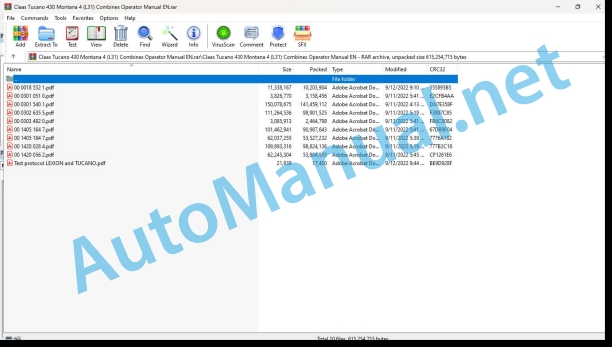
00 0018 552 1.pdf
00 0301 051 0.pdf
00 0301 540 1.pdf
00 0302 635 5.pdf
00 0303 482 0.pdf
00 1405 164 7.pdf
00 1405 184 7.pdf
00 1420 028 4.pdf
00 1420 056 2.pdf
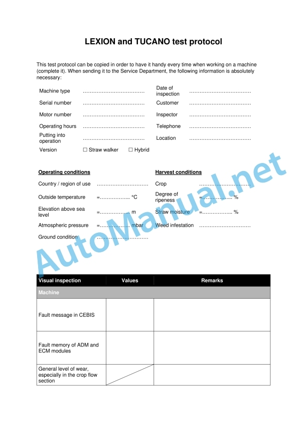
Test protocol LEXION and TUCANO.pdf
00 0018 552 1.pdf:
TELEMATICS Website
Table of contents
1 About this Concise Operator’s Manual
1.1 Notes on the manual
1.1.1 Validity of manual
1.1.2 Notes regarding the Concise Operator’s Manual
1.1.3 Notes on warranty
2 Safety
2.1 Intended use
2.1.1 Proper use
3 Product description
3.1 Overview and method of operation
3.1.1 TELEMATICS product variants
3.1.2 TONI (TELEMATICS on implements)
3.1.3 Fleet View
3.1.4 TELEMATICS basic
3.1.5 TELEMATICS advanced
3.1.6 TELEMATICS professional
3.1.7 TELEMATICS app
4 Operating and control elements
4.1 TELEMATICS overview
4.1.1 Illustration conventions of buttons and navigation elements
4.1.2 Symbols and colours
4.2 Menu structure
4.2.1 Start screen
4.2.2 TELEMATICS website site map
4.2.3 Main menu overview
4.2.4
4.2.5
4.2.6
00 0301 051 0.pdf:
PROFI CAM 3
Table of contents
1 Introduction
1.1 Notes on the manual
1.1.1 Validity of manual
1.1.2 Information about this Operator’s Manual
1.1.3 Symbols and notes
1.1.4 Optional equipment
1.1.5 Qualified specialist workshop
1.1.6 Maintenance information
1.1.7 Warranty notes
1.1.8 Spare parts and technical questions
1.2 Intended use
1.2.1 Intended use
1.2.2 Reasonably foreseeable misuse
2 Safety
2.1 Identifying warnings
2.1.1 Hazard signs
2.1.2 Signal word
2.2 Safety rules
2.2.1 Meaning of Operator’s Manual
2.2.2 Observing safety decals and warnings
2.2.3 Optional equipment and spare parts
3 Product description
3.1 Overview and method of operation
3.1.1 How the PROFI CAM works
3.2 Identification plates and identification number
3.2.1 Position of identification plates
3.2.2 Explanation of PROFI CAM identification plate
3.3 Information on the product
3.3.1 CE marking
4 Operating and control elements
4.1 Camera system
4.1.1 Camera system monitor
4.2 Menu structure
4.2.1 Main menu
4.2.2
4.2.3
4.2.4
4.2.5
4.2.6
5 Technical specifications
5.1 PROFI CAM
5.1.1 Monitor
5.1.2 Camera
5.1.3 Switch box
5.1.4 Degree of protection against foreign bodies and water
6 Preparing the product
6.1 Shutting down and securing the machine
6.1.1 Switching off and securing the machine
6.2 Prior to operation
6.2.1 Carry out prior to operation
6.2.2 Installing the sun protection
6.2.3 Aligning the camera
6.2.4 Connecting the camera electrics
7 Operation
7.1 Monitor
7.1.1 Switching on the monitor
7.1.2 Calling up the menu
7.1.3 Setting a menu item
7.1.4 Setting the image orientation
7.1.5 Setting automatic screen darkening
7.1.6 Image mirroring
7.1.7 Setting the trigger view
7.1.8 Setting the follow-up time for trigger view
7.1.9 Setting the display mode
7.1.10 Activating/deactivating a display mode
8 Faults and remedies
8.1 Electrical and electronic system
8.1.1 Overview of problems on PROFI CAM camera system
8.1.2 Replacing the switch box fuse
9 Maintenance
9.1 Maintenance intervals
9.1.1 Every 10 operating hours or daily
9.2 Camera system
9.2.1 Checking the camera system for dirt
9.2.2 Cleaning the camera
9.2.3 Cleaning the switch box
9.2.4 Cleaning the monitor
10 Placing out of operation and disposal
10.1 General Information
10.1.1 Putting out of operation and disposal
11 Technical terms and abbreviations
11.1 Abbreviations
11.1.1 Units
11.1.2 Abbreviations
11.1.3 Technical terms
00 0301 540 1.pdf:
Mercedes-Benz OM936LA(Stage IV and V)
Table of contents
Introduction
General information
Validity of manual
Using the manual
Text and figures
Document structure based on sub-assemblies
Search and find
Directions
Abbreviations
Technical terms
General repair instructions
Technical specifications
Information on technically correct repairs
Self-locking bolts
Liquid locking compound
Steel roller chains
Tensioning
Chain connector
Chain connector type E with spring
Chain connector type G with wire
Chain connector type S with cotter pins
Taper ring fasteners
Dismounting
Installation
Gib head key connections
Dismounting
Installation
Lock collar bearing
Dismounting
Installing
Adapter sleeve bearing
Dismounting
Installation
Chuck bushing
Removing
Dismounting of version A
Dismounting of version B
Installing
Chuck bushing version A
Chuck bushing version B
Circlips
Ferrule fittings
Screwing in
Leaky ferrule fittings
Sealing cone fittings
Hydraulic hoses
Hose placement
Treatment of sealing faces
Spare parts
Torque settings
Tightening torques for metric ISO screw thread
Tightening torques for metric fine thread
Tightening torques for screwed pipe connections with sealing cone joint and hydraulic threaded joints with soft core seal
Tightening torques for hydraulic fittings with ferrule
Tightening torques for hydraulic male connectors SDS shape B and E
Tightening torques for hydraulic swivel screw fittings
Tightening torque for hollow screws (with copper sealing ring)
Tightening torques for hydraulic male connectors SDE shape H, with adjustable direction
Tightening torques for brake line screw fittings
Tightening torques for worm drive hose clamps
Tightening torques for hose clamps with round pins
CCN explanation
CCN (CLAAS Component Number)
Electric systems standard
Hydraulic system standard
CCN (CLAAS Component Number)
General information
Important
Hazard signs
Signal word
Regulations for avoiding accidents with personal injuries
Testing, adjusting and repair work
Engine operation
Suspended loads
Working on piping and hoses
Work on the Common Rail System
Working on the electric system
Working on the hydraulic system
Electric welding
Painting work
Working with urea solution
Information on how to avoid damage and premature wear
Liability limitation
Shutting down and storage
Regulations for avoiding health and environmental damage
Precautionary measures for protection against health and environmental damage
Disposal of operating utilities and auxiliary operating utilities
Information for working on the diesel engine
Accident protection
Cleanliness
Installation instructions
Engine overhaul
Putting into operation after an engine overhaul
First aid measures
01 Engine
0102 Complete component
Type design
Engine data
OM 936 LA
Engine description
Engine components
Engine components
Actuators
Ignition order
Cranking the engine
Special tool for built-in engine
Special tool for when the engine is removed
Special tool for setting the engine to ignition TDC
Cranking the engine in built-in condition
Cranking the engine in removed condition
Setting the engine to ignition TDC
Setting the engine to ignition TDC: Removing
0105 Engine suspension
Lifting eyes
Technical specifications
0110 Engine housing
Technical specifications
Special tool
Removing
Installing
Crankshaft front seal
Technical specifications
Special tool
Removing
Installing
Crankshaft rear seal
Technical specifications
Special tool
Removing
Installing
Housing cover
Technical specifications
Special tool
Removing
Installing
Timing housing
Technical specifications
Work preparation
Removing
Installing
Flywheel housing
Technical specifications
Special tool
Removing
Installing
0115 Engine unit
Technical specifications
Special tool
Removing
Disassembling
Checking
Assembling
Installing
Checking the combustion pressure
Connecting rod
Technical specifications
Removing
Checking
Installing
Cylinder bore
Technical specifications
Special tool
Checking
Crankshaft
Technical specifications
Special tool
Removing the crankshaft
Checking the crankshaft
Installing the crankshaft
Crankshaft main bearings
Technical specifications
Special tool
Removing
Installing
Oscillation damper
Technical specifications
Special tool
Removing
Installing
Flywheel
Technical specifications
Special tool
Removing
Checking
Installing
0120 Cylinder head / Valves / Idler gear
Valve cover
Technical specifications
Removing
Installing
Rocker arm frame
Technical specifications
Removing
Installing
Camshaft
Technical specifications
Special tool
Removing
Installing
Checking
Cylinder head
Technical specifications
Special tool
Removing
Installing
Cleaning
Checking
Rocker arm mechanism
Technical specifications
Removing
Installing
Technical specifications
Special tool
Removing
Installing
Checking the valves
Adjusting the valve lash
Valve springs and valve stem seals
Technical specifications
Special tool
Removing
Installing
Gear drive
Technical specifications
Removing
Installing
Checking
Checking and adjusting the backlash
0125 Injection / Fuel system
High-pressure lines and rail
Technical specifications
Special tool
Removing
Installing
Injectors
Technical specifications
Work preparation
Special tool
Removing
Installing
Protective sleeve
Technical specifications
Special tool
Removing
Installing
Fuel pump (low pressure)
Technical specifications
Work preparation
Removing
Installing
Fuel pump (high pressure)
Technical specifications
Work preparation
Special tool
Removing
Installing
Fuel pump drive gear (high pressure)
Technical specifications
Work preparation
Special tool
Removing
Installing
Fuel filter module
Technical specifications
Work preparation
Removing
Installing
Fuel pre-heating heater element
Technical specifications
Work preparation
Removing
Installing
Fuel control valve (Y643-MB)
Technical specifications
Work preparation
Removing
Installing
Test device for fuel pressure measurement
Technical specifications
Work preparation
Special tool
Installing
0130 Lubricating oil system
Lubricating oil system
Special tool
Pre-filling
Installing
Oil spray nozzle
Technical specifications
Removing
Installing
Oil/coolant module
Technical specifications
Work preparation
Removing the oil/coolant module
Installing the oil/coolant module
Removing the heat exchanger
Installing the heat exchanger
Oil pump
Technical specifications
Work preparation
Removing
Installing
0135 Cooling system
Special tool
Draining
Filling up
Cleaning the coolant circuit
Coolant pump
Technical specifications
Work preparation
Removing
Installing
Coolant thermostat
Technical specifications
Work preparation
Removing
Installing
0140 Exhaust system
Exhaust gas recirculation cooler
Technical specifications
Work preparation
Special tool
Removing the exhaust gas recirculation tube downstream of exhaust gas recirculation cooler
Installing the exhaust gas recirculation tube downstream of exhaust gas recirculation cooler
Removing the exhaust gas recirculation tube upstream of exhaust gas recirculation cooler
Installing the exhaust gas recirculation tube upstream of exhaust gas recirculation cooler
Removing the exhaust gas recirculation cooler
Installing the exhaust gas recirculation cooler
Checking if the exhaust gas recirculation cooler shows a pressure drop
Exhaust gas recirculation cooler bracket
Technical specifications
Work preparation
Removing the exhaust gas recirculation cooler bracket
Installing the exhaust gas recirculation cooler bracket
Exhaust gas recirculation cooler bracket
Technical specifications
Work preparation
Removing the exhaust gas recirculation cooler bracket
Installing the exhaust gas recirculation cooler bracket
Exhaust manifold
Technical specifications
Work preparation
Removing
Installing
Exhaust manifold
Technical specifications
Work preparation
Removing
Installing
Turbocharger
Technical specifications
Work preparation
Removing
Installing
Turbocharger
Technical specifications
Work preparation
Removing
Installing
Charge pressure actuator
Technical specifications
Work preparation
Removing
Installing
Exhaust gas recirculation actuator (Y621-MB)
Technical specifications
Work preparation
Removing
Installing
Exhaust turbocharger oil lines
Technical specifications
Work preparation
Removing
Installing
Exhaust turbocharger oil lines
Technical specifications
Work preparation
Removing
Installing
0145 Air intake
Charge air housing
Technical specifications
Work preparation
Removing the left charge air tube
Installing the left charge air tube
Removing the right charge air tube
Installing the right charge air tube
Removing the charge air manifold
Installing the charge air distributor
0150 Engine attachment parts
Electric starting motor
Technical specifications
Removing
Installing
Alternator (G002, G003 / G2-MB)
Technical specifications
Special tool
Removing the alternator
Installing the alternator
Alternator drive belt tensioner
Technical specifications
Installation instructions
Resonance vessel
Technical specifications
Installation instructions
Air compressor
Technical specifications
Work preparation
Special tool
Removing the air compressor
Installing the air compressor
Removing the drive gearwheel
Installing the drive gearwheel
0155 Engine control
Control unit
Technical specifications
Installation instructions
0165 Exhaust gas aftertreatment
Urea pump (M047 / M25-MB)
Technical specifications
Work preparation
Special tool
Removing the urea pump
Installing the urea pump
Removing the pressure relief valve
Installing the pressure relief valve
Removing the inlet nozzle filter
Installing the inlet nozzle filter
Removing the frost protection element
Installing the frost protection element
Urea dosing unit (A089 / A67-MB)
Technical specifications
Work preparation
Special tool
Removing the dosing unit
Installing the dosing unit
Removing the filter
Installing the filter
00 0303 482 0.pdf:
PROFI CAM 4
Table of contents
1 Introduction
1.1 Notes on the manual
1.1.1 Validity of manual
1.1.2 Information about this Operator’s Manual
1.1.3 Symbols and notes
1.1.4 Optional equipment
1.1.5 Qualified specialist workshop
1.1.6 Maintenance information
1.1.7 Notes on warranty
1.1.8 Spare parts and technical questions
1.2 Intended use
1.2.1 Intended use
1.2.2 Reasonably foreseeable misuse
2 Safety
2.1 Identifying warnings
2.1.1 Hazard signs
2.1.2 Signal word
2.2 Safety rules
2.2.1 Meaning of Operator’s Manual
2.2.2 Structural changes
2.2.3 Optional equipment and spare parts
2.2.4 Operation only following proper putting into operation
2.2.5 Technical status
2.2.6 Respecting technical limit values
Respecting technical limit values
2.2.7 Hazards when driving on roads and fields
3 Product description
3.1 Overview and method of operation
3.1.1 How the PROFI CAM works
3.2 Identification plates and identification number
3.2.1 Identification plates
3.3 Information on the product
3.3.1 CE marking
4 Operating and display elements
4.1 Camera system
4.1.1 Camera system monitor
4.1.2 CEBIS
4.2 Menu structure
4.2.1 Main menu
4.2.2
4.2.3
4.2.4
4.2.5
4.2.6
5 Technical specifications
5.1 PROFI CAM
5.1.1 Monitor
5.1.2 Camera
5.1.3 Switch box
6 Preparing the product
6.1 Switching off and securing the machine
6.1.1 Switching off and securing the machine
6.2 Prior to putting into operation
6.2.1 Carry out prior to operation
6.2.2 Installing the sun protection
6.2.3 Aligning the camera
7 Operation
7.1 Monitor
7.1.1 Switching on the monitor
7.1.2 Calling up the menu
7.1.3 Setting a menu item
7.1.4 Setting the image orientation
7.1.5 Setting automatic screen darkening
7.1.6 Image mirroring
7.1.7 Setting the trigger view
7.1.8 Setting the follow-up time for trigger view
7.1.9 Setting the display mode
7.1.10 Activating/deactivating a display mode
8 Faults and remedies
8.1 Electric and electronic system
8.1.1 Overview of problems on PROFI CAM camera system
9 Maintenance
9.1 Maintenance intervals
9.1.1 Every 10 operating hours or daily
9.2 Camera system
9.2.1 Checking the camera system for dirt
9.2.2 Cleaning the camera
9.2.3 Cleaning the switch box
9.2.4 Cleaning the monitor
10 Putting out of operation and disposal
10.1 General information
10.1.1 Putting out of operation and disposal
11 Technical terms and abbreviations
11.1 Abbreviations
11.1.1 Units
11.1.2 Abbreviations
11.1.3 Technical terms
00 1405 164 7.pdf:
GPS PILOT
Table of contents
1 Introduction
1.1 General information
1.1.1 Validity of Manual
1.1.2 Information about this Operator’s Manual
1.1.3 Symbols and notes
1.1.4 Optional equipment
1.1.5 Qualified specialist workshop
1.1.6 Maintenance notes
1.1.7 Notes on warranty
1.1.8 Spare parts and technical questions
1.1.9 Licensing for road traffic
Sample report
Clearance certificate
General operating permit
1.2 Intended use
1.2.1 Intended use
1.2.2 Reasonably foreseeable misuse
2 Safety
2.1 Identifying warnings
2.1.1 Hazard signs
2.1.2 Signal word
2.2 Safety rules
2.2.1 Meaning of Operator’s Manual
2.2.2 Update of terminal software
2.2.3 Requirements made on all persons working with the product
2.2.4 Hazard areas
Hazard areas
2.2.5 Interaction between the control terminal and the machine or tractor
2.2.6 Structural changes
2.2.7 Optional equipment and spare parts
2.2.8 Use of USB devices
2.2.9 Operation only following proper putting into operation
2.2.10 Technical status
2.2.11 Hazard from damage on the product
2.2.12 Respecting technical limit values
Respecting technical limit values
2.2.13 Preparing the product for road travel
2.2.14 Hazards when driving on the road with an ISOBUS implement
Switching on the terminal during road travel.
2.2.15 Hazards when driving on the road and on the field
2.2.16 Electrocution by electrical system
2.2.17 Potentially fatal electric shock from overhead lines
2.2.18 Liquids under pressure
2.2.19 Maintenance operations and repair work
2.2.20 Driving with the GPS PILOT
Road travel
Fieldwork
2.2.21 Working with Task Control* and Section Control*
3 Product description
3.1 Overview and method of operation
3.1.1 Overview of GPS PILOT – Hydraulic system
3.1.2 Overview of GPS PILOT – Steer ready
3.1.3 Overview of GPS PILOT FLEX
3.1.4 Overview of GPS PILOT ex works
3.1.5 Overview of the S10 terminal
3.1.6 Overview of navigation computer (ECU)
3.1.7 Electric steering wheel
3.1.8 Overview of correction signals
EGNOS/WAAS/MSAS
Omnistar HP / XP / G2
RTK FIELD BASE and BASELINE HD
RTK FARM BASE
3.1.9 Module overview
BASELINE HD
RTK FIELD BASE
RTK (Motorola)
RTK FARM BASE
3.2 Safety devices
3.2.1 Automatic cut-out when the maximum speed is exceeded
3.2.2 Automatic cut-out when the speed falls below the minimum
3.2.3 Seat contact switch
3.2.4 Manual override
Electric steering wheel
3.3 Optional equipment
3.3.1 GPS L2*
3.3.2 GLONASS*
3.3.3 TURN IN*
3.3.4 AUTO TURN*
3.3.5 Task Control*
Task Control Basic*
Task Control Geo*
3.3.6 Section Control*
3.4 Identification plates and identification numbers
3.4.1 GPS PILOT identification plate
3.4.2 Identification plate of terminal
3.4.3 Identification plate of navigation controller
4 Operating and display elements
4.1 GPS PILOT
4.1.1 Master switch and drive switch
4.2 Overview of the S10 terminal
4.2.1 Layout conventions of buttons and displays
4.3 GPS PILOT menu structure
4.3.1 Start menu
Start menu without Task Control*
Start menu with Task Control*
4.3.2 Menu overview
4.3.3 Overview of display field
4.3.4
4.3.5
4.3.6
John Deere Repair Technical Manual PDF
New Holland Service Manual PDF
John Deere Repair Technical Manual PDF
John Deere Repair Technical Manual PDF
John Deere 18-Speed PST Repair Manual Component Technical Manual CTM168 10DEC07
John Deere Repair Technical Manual PDF
John Deere PowerTech M 10.5 L and 12.5 L Diesel Engines COMPONENT TECHNICAL MANUAL CTM100 10MAY11
John Deere Repair Technical Manual PDF
John Deere Repair Technical Manual PDF
John Deere Transmission Control Unit Component Technical Manual CTM157 15JUL05
John Deere Repair Technical Manual PDF
John Deere 16, 18, 20 and 24HP Onan Engines Component Technical Manual CTM2 (19APR90)
John Deere Parts Catalog PDF
John Deere Tractors 7500 Parts Catalog CPCQ26568 30 Jan 02 Portuguese

