Claas Tucano 480-470 (C36) Combines Repair Manual EN
$300.00
- Model: Tucano 480-470 (C36) Combines
- Type Of Manual: Repair Manual
- Language: EN
- Format: PDF(s)
- Size: 21.9 MB
File List:
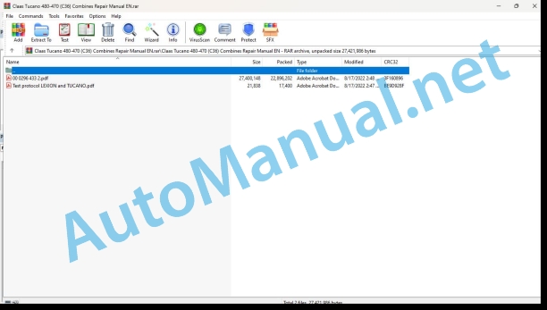
00 0296 433 2.pdf
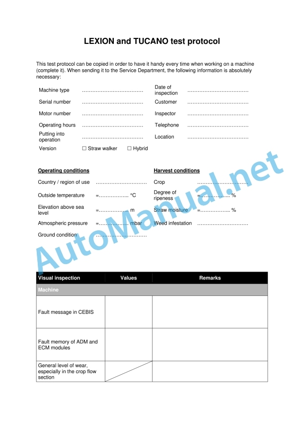
Test protocol LEXION and TUCANO.pdf
00 0296 433 2.pdf:
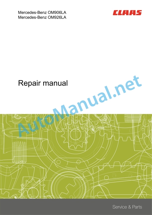
Mercedes-Benz OM906LAMercedes-Benz OM926LA
Table of contents
Introduction
General information
Validity of manual
Handling the manual
Texts and figures
Document structure based on the assembly structure
Search and find
Directions
Abbreviations
Technical terms
General repair instructions
Technical specifications
Information on proper repairs
Self-locking bolts
Liquid locking compound
Steel roller chains
Tensioning
Chain connector
Taper ring fasteners
Dismounting
Installation
Gib head key joints
Dismounting
Installation
Lock collar bearing
Dismounting
Installation
Adapter sleeve bearings
Dismounting
Installation
Chuck bushing
Dismounting
Installation
Circlips
Ferrule fittings
Screwing in
Non-tight ferrule connection
Sealing cone fittings
Hydraulic hoses
Hose placement
Treatment of sealing faces
Spare parts
Torque settings
Tightening torques for metric standard threads
Tightening torques for metric fine thread screws
Tightening torques for hydraulic screw fittings and air conditioner screw fittings with sealing cone and O-ring according to DIN 3865
Tightening torques for hydraulic screw fittings with ferrule according to DIN 3861
Tightening torques for SDS hydraulic male connectors
Tightening torques for hydraulic swivel fittings
Tightening torques for hollow screws DIN 7643
Tightening torques for direction-adjustable SDE hydraulic male connectors
Tightening torques for brake line screw fittings
Tightening torques for worm drive hose clamps
Tightening torque for spring-loaded worm drive hose clamps
CCN explanation
CCN (CLAAS Component Number)
Electric systems standard
Hydraulic system standard
CCN (CLAAS Component Number)
General information
Of special importance
Identification of warning and danger signs
Regulations for avoiding accidents with personal injuries
Testing, adjusting and repair work
Engine operation
Suspended loads
Working on piping and hoses
Work on the Common Rail System
Working on the electric system
Working on the hydraulic system
Electric welding
Painting work
Working with urea solution
Information on how to avoid damage and premature wear
Liability limitation
Shutting down and storage
Regulations for avoiding health and environmental damage
Precautionary measures for protection against health and environmental damage
Disposal of operating utilities and auxiliary operating utilities
Information for working on the diesel engine
Accident protection
Cleanliness
Installation instructions
Engine overhaul
Putting into operation after an engine overhaul
First aid measures
01 Engine
0102 Complete component
Type design
Engine data
Engine description
Engine components
Ignition order
Cranking the engine
Special tool for built-in engine
Special tools for removed engine
Cranking the engine in built-in condition
Cranking the engine in removed condition
0105 Engine suspension
Lifting eyes
Technical specifications
0110 Engine housing
Oil sump
Special tool
Technical specifications
Installation
Crankshaft front seal
Special tool
Technical specifications
Installation
Crankshaft rear seal
Special tool
Technical specifications
Installation
Timing housing
Special tool
Technical specifications
Installation
Oil separator
Technical specifications
0115 Engine unit
Special tool
Technical specifications
Disassembly
Checking
Assembly
Installation
Measuring the excess dimension
Connecting rod
Technical specifications
Checking
Installation
Cylinder bore
Technical specifications
Checking
Gear of crankshaft
Special tool
Installation instructions
Crankshaft
Special tool
Technical specifications
Checking
Installation
Oscillation damper
Technical specifications
Installation instructions
Flywheel
Special tool
Technical specifications
Checking
Installation
Replace ring gear
0120 Cylinder head / Valves / Idler gear
Valve cover
Technical specifications
Installation
Cylinder head
Special tool
Technical specifications
Checking
Installation
Special tool
Technical specifications
Installation instructions
Checking the valves
Adjusting the valve lash
Rocker lever
Disassembly
Assembly
Installation
Valve springs and valve stem seals
Special tool
Technical specifications
Installation
Valve guide
Work preparation
Special tool
Technical specifications
Checking
Installation
Camshaft
Special tool
Technical specifications
Checking
Installation
0125 Injection – / Fuel system
Fuel system
Cylinder head injection line
Special tool
Technical specifications
Installation instructions
Nozzle holder combination
Work preparation
Special tool
Technical specifications
Installation
Protective sleeve
Special tool
Technical specifications
Installation instructions
Plug-on pump
Special tool
Work preparation
Technical specifications
Installation
Fuel pump
Technical specifications
Installation
Fuel filter housing
Technical specifications
0130 Lubricating oil system
Lubricating oil system
Work preparation
Special tool
Pre-filling
Cleaning the main oil channel
Oil spray nozzle
Special tool
Technical specifications
Installation
Oil filter housing
Technical specifications
Applies to type designs: 926.959 and 926.970
Installation
Applies to type designs: 926.959 and 926.970
Oil cooler
Technical specifications
Installation
Oil pump
Work preparation
Special tool
Technical specifications
Installation
Installing the radial seal
0135 Cooling system
Special tool
Technical specifications
Draining
Filling up
Cleaning the coolant circuit
Coolant pump
Technical specifications
Installation
Coolant thermostat
Work preparation
Technical specifications
Checking
Installation
0140 Exhaust system
Exhaust manifold
Technical specifications
Applies to type designs: 926.959 and 926.970
Installation
Applies to type designs: 926.959 and 926.970
Exhaust turbo charger
Special tool
Technical specifications
Installation
Checking
Checking the axial play
Checking the radial play
Flap nozzle
Technical specifications
Installation
Catalyst
Work preparation
Technical specifications
Installation instructions
0145 Air intake
Intake housing
Technical specifications
Installation instructions
0150 Engine attachment parts
Electric starting motor
Work preparation
Technical specifications
Installation
Removing the solenoid switch
Installing the solenoid switch
Alternator
Special tool
Technical specifications
Installation
Removing the pulley
Installing the pulley
Alternator
Special tool
Technical specifications
Installation
Removing the pulley
Installing the pulley
Alternator drive belt tensioner
Technical specifications
Installation instructions
Air compressor
Technical specifications
Installation
Checking the oil thrown out
0155 Engine control
MR/PLD control unit
Technical specifications
Installation instructions
0165 Exhaust gas aftertreatment
Exhaust treatment system
Work preparation
Special tool
Technical specifications
Checking the urea solution (purity)
Checking the urea solution (density)
Urea heater valve
Work preparation
Special tool
Technical specifications
Installation
Urea pump
Work preparation
Special tool
Technical specifications
Installation
Removing the pressure accumulator
Installing the pressure accumulator
Removing the dump valve
Installing the dump valve
Removing the intake filter
Installing the intake filter
Checking the electric wiring loom
Filling the accumulator
Urea dosing unit
Work preparation
Special tool
Technical specifications
Installation instructions
Flushing
Urea injector
John Deere Repair Technical Manual PDF
John Deere Repair Technical Manual PDF
John Deere Repair Technical Manual PDF
John Deere Repair Technical Manual PDF
John Deere Repair Technical Manual PDF
John Deere Repair Technical Manual PDF
John Deere 16, 18, 20 and 24HP Onan Engines Component Technical Manual CTM2 (19APR90)
John Deere Parts Catalog PDF
John Deere Tractors 6300, 6500, and 6600 Parts Catalog CQ26564 (29SET05) Portuguese
John Deere Repair Technical Manual PDF
John Deere Repair Technical Manual PDF


