Claas Crop Sensor Isaria (B61) Digital Solutions Technical System EN
$300.00
- Model: Crop Sensor Isaria (B61) Digital Solutions
- Type Of Manual: Technical System
- Language: EN
- Format: PDF(s)
- Size: 5.6 MB
File List:
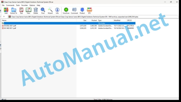
00 0302 343 1.pdf
00 1403 501 1.pdf
00 0302 343 1.pdf:
PROFI CAM 3
Table of contents
General information
Marking of warnings and hazard prevention notes
First-aid measures
CCN explanation
CCN (CLAAS Component Number)
Electric system standard
Overview
Hydraulic system standard
Overview
CCN (CLAAS Component Number)
10 Electrical / Electronic equipment
1030 Board computer / Indicators
Camera system
Description of function
1097 Testing / Measuring / Adjusting
Testing / measuring / adjusting the PROFI CAM
Checking the fuse in the video channel select box (C102)
Testing the video camera connector (C055)
1098 Fault / remedy
Fault / remedy PROFI CAM
The video monitor (C101) shows no image or cannot be switched on (indicator light fails to light up)
Video monitor (C102) displays a blue image either permanently or temporarily
The video monitor image is blurred
Replacing the fuse in the video channel select box (C102)
Connection and connecting cable with video camera (C055)
00 1403 501 1.pdf:
CROP SENSOR
Table of contents
CCN explanation
CCN (CLAAS Component Number)
Electric systems standard
Overview
CCN (CLAAS Component Number)
Introduction
Safety rules
Safety and hazard precautions
Validity of manual
Validity of the manual
10 Electrical / Electronic equipment
1012 Modules / sensors
Module overview
Module arrangement
Description of function
Module A173 – Crop sensor module
Designations
Designations
Module A175 – ISO-Master module crop quality
Designations
Designations
1080 Electronic circuit diagram
Introduction into circuit diagrams
Overview of designations
CLAAS cable designation
Wire colours
Power supply
Actuators
Actual value switch (output = 0 or 1)
Internal connections
Overview of CAN Bus system
Communication
Standards
Electric circuit diagrams (SCM)
SCM 01 – Electric circuit diagram
Designation
Connector
SCM 02 – Overview of modules
Designation
SCM 03 – plug
Designation
Connector database (chp CLAAS)
Example of key number representation (CHP)
Key number (CHP)
Connector representation (CHP)
1085 Networks
BUS systems (CAN)
Description of function
Diagnosis by fault codes
FMI failure code (Failure Mode Indicator)
FMI failure code (Failure Mode Indicator)
FMI 00 (Signal too high)
FMI 01 (Signal too low)
FMI 02 (Erratic signal)
FMI 03 (Voltage too high)
FMI 04 (Voltage too low)
FMI 05 (Current too low)
FMI 06 (Current too high)
FMI 07 (Mechanical failure)
FMI 08 (Abnormal frequency signal)
FMI 09 (Communication error)
FMI 10 (Rate of signal change too fast)
FMI 11 (multiple faults)
FMI 12 (ECU defective)
FMI 13 (Signal outside of calibration range)
FMI 16 (Parameter not available)
FMI 17 (ECU not responding)
FMI 18 (Power supply failure)
FMI 19 (Software conditions not met)
FMI 95 (no signal change)
FMI 96 (CAN Bus system defective)
FMI 97 (Erratic condition)
FMI 98 (Warning)
FMI 99 (Info)
Fault codes
Fault codes
DTC (Diagnostic Trouble Code) overview
Position of components
Electric system
A Terminal / modules
B Sensors
M Motor (electrical)
John Deere Repair Technical Manual PDF
John Deere Repair Technical Manual PDF
John Deere 18-Speed PST Repair Manual Component Technical Manual CTM168 10DEC07
John Deere Repair Technical Manual PDF
John Deere Diesel Engines POWERTECH 2.9 L Component Technical Manual CTM126 Spanish
John Deere Repair Technical Manual PDF
John Deere Repair Technical Manual PDF
John Deere Parts Catalog PDF
John Deere Harvesters 8500 and 8700 Parts Catalog CPCQ24910 Spanish
John Deere Repair Technical Manual PDF
John Deere Repair Technical Manual PDF
John Deere POWERTECH E 4.5 and 6.8 L Diesel Engines TECHNICAL MANUAL 25JAN08
John Deere Repair Technical Manual PDF


