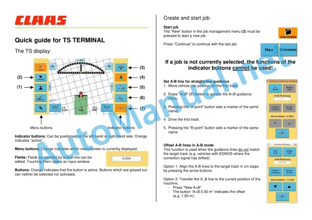
Claas Gps Pilot Ts (B81) Digital Solutions Operator Manual EN
$50.00
- Model: Gps Pilot Ts (B81) Digital Solutions
- Type Of Manual: Operator Manual
- Language: EN
- Format: PDF(s)
- Size: 76.3 MB
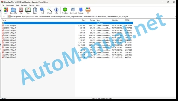
File List:
00 0018 584 4.pdf
00 0018 647 2.pdf
00 0018 652 1.pdf
00 0019 424 0.pdf
00 0301 051 0.pdf
00 0303 482 0.pdf
00 1400 062 1.pdf
00 1400 108 1.pdf
00 1400 240 0.pdf
00 1400 243 0.pdf
00 1400 244 0.pdf
00 1400 638 3.pdf
00 1402 805 1.pdf
00 2348 427 0.pdf
00 0018 584 4.pdf:
EASY on board app
Table of contents
1 Introduction
1.1 Notes on the manual
1.1.1 Information about this Operator’s Manual
1.1.2 Symbols and notes
1.1.3 Notes regarding warranty
1.1.4 Technical requirements
1.2 Intended use
1.2.1 Intended use
1.2.2 Reasonably foreseeable misuse
1.3 Softwareupdate
1.3.1 Installing updates
1.3.2 Updating the operating system
1.4 Faults and remedies
1.4.1
1.4.2 Fault message: Screen locked
1.5 Technical terms and abbreviations
1.5.1 Technical terms
1.5.2 Units
1.5.3 Abbreviations
2.1 Identifying warnings
2.1.1 Hazard signs
2.1.2 Signal word
2.2 Safety rules
2.2.1 Meaning of Operator’s Manual
2.2.2 Requirements made on all persons working with the product
2.2.3 Hazard areas
2.2.4 Check interactions with self-propelled machines / tractors and implements
2.2.5 Structural changes
2.2.6 Optional equipment and spare parts
2.2.7 Technical status
2.2.8 Hazard caused by damage to the product
2.2.9 Visibility of work area
2.2.10 Glare and reflections
2.2.11 Unintentional triggering of functions
2.2.12 Hazards caused by signal tones
2.2.13 Unauthorised use
2.2.14 Use of mobile terminal outside the cab
2.2.15 Follow the safety instructions
2.2.16 Respecting technical limit values
2.2.17 Preparing the product for road travel
2.2.18 Hazards when driving on the road and on the field
2.2.19 Hazards when driving on the road with an ISOBUS implement
2.2.20 Hazards caused by switching off the app while driving
2.2.21 Hazards from disturbance of WLAN environment
2.2.22 Hazards from covering up the App
2.2.23 Hazards caused by malfunctions of the app
2.2.24 Lifted machine parts and loads
3 EASY on board App
3.1 Operating and display elements
3.1.1 Overview of the EASY on board App
3.1.2 Overview of function bar
3.1.3 Cockpit bar overview
3.1.4 Functions of the EASY on board App
3.1.5 Using the number pad
3.1.6 Using the keyboard
3.2 Operation
3.2.1 Selecting a module
3.2.2 Activating or deactivating modules
3.2.3 Activating or changing the licence
3.2.4 Setting the volume
3.2.5 Closing the app
4 Documentation
4.1 Product description
4.1.1 Requirements
4.1.2 Task data
4.1.3 Product options
4.1.4 App operation in the background
4.2 Operating and display elements
4.2.1
4.2.2 Tasks
4.2.3 Fields
4.2.4 Harvesting
4.2.5 Seeds
4.2.6 Consumables
4.2.7 Machines and implements
4.2.8 Persons
4.2.9 Remark
4.2.10
4.2.11 Entering quantities
4.3 Creating a task
4.3.1 Creating a task
4.3.2 Copying a task
4.3.3 Selecting fields
4.3.4 Creating a new field
4.3.5 Selecting the harvest type
4.3.6 Selecting seeds
4.3.7 Select consumables
4.3.8 Selecting machines and implements
4.3.9 Selecting persons
4.3.10 Save task
4.4 Documentation
4.4.1 Starting the task
4.4.2 Stopping the task
4.4.3 Completing the task
4.4.4 Synchronising an task
4.4.5 Exporting data
4.4.6 Deleting settings
5 ISO terminal
5.1 Product description
5.1.1
5.1.2 Connecting the ISO terminal
5.2 Operating and display elements
5.2.1 Overview of the ISO terminal
5.2.2
5.2.3 Controlling the machine without a USB connection to the CWI
5.3 Programmable keys
5.3.1 Assigning a key assignment
5.3.2 Programming the key assignment
5.3.3 Editing a key assignment
5.3.4 Deleting key assignments
6 Adjustments
6.1 Operating and display elements
6.1.1 Settings
6.2 Adjustments
6.2.1 Resetting the data source
6.2.2 Activating ISOBUS communication
6.2.3 Checking the synchronisation status
6.2.4 Sending an error report
7.1 Adjustments
7.1.1 Where do I find the version number?
7.1.2 Can I change to another app while this app is running?
00 0301 051 0.pdf:
PROFI CAM 3
Table of contents
1 Introduction
1.1 Notes on the manual
1.1.1 Validity of manual
1.1.2 Information about this Operator’s Manual
1.1.3 Symbols and notes
1.1.4 Optional equipment
1.1.5 Qualified specialist workshop
1.1.6 Maintenance information
1.1.7 Warranty notes
1.1.8 Spare parts and technical questions
1.2 Intended use
1.2.1 Intended use
1.2.2 Reasonably foreseeable misuse
2.1 Identifying warnings
2.1.1 Hazard signs
2.1.2 Signal word
2.2 Safety rules
2.2.1 Meaning of Operator’s Manual
2.2.2 Observing safety decals and warnings
2.2.3 Optional equipment and spare parts
3 Product description
3.1 Overview and method of operation
3.1.1 How the PROFI CAM works
3.2 Identification plates and identification number
3.2.1 Position of identification plates
3.2.2 Explanation of PROFI CAM identification plate
3.3 Information on the product
3.3.1 CE marking
4 Operating and control elements
4.1 Camera system
4.1.1 Camera system monitor
4.2 Menu structure
4.2.1 Main menu
4.2.2
4.2.3
4.2.4
4.2.5
4.2.6
5 Technical specifications
5.1 PROFI CAM
5.1.1 Monitor
5.1.2 Camera
5.1.3 Switch box
5.1.4 Degree of protection against foreign bodies and water
6 Preparing the product
6.1 Shutting down and securing the machine
6.1.1 Switching off and securing the machine
6.2 Prior to operation
6.2.1 Carry out prior to operation
6.2.2 Installing the sun protection
6.2.3 Aligning the camera
6.2.4 Connecting the camera electrics
7 Operation
7.1 Monitor
7.1.1 Switching on the monitor
7.1.2 Calling up the menu
7.1.3 Setting a menu item
7.1.4 Setting the image orientation
7.1.5 Setting automatic screen darkening
7.1.6 Image mirroring
7.1.7 Setting the trigger view
7.1.8 Setting the follow-up time for trigger view
7.1.9 Setting the display mode
7.1.10 Activating/deactivating a display mode
8 Faults and remedies
8.1 Electrical and electronic system
8.1.1 Overview of problems on PROFI CAM camera system
8.1.2 Replacing the switch box fuse
9 Maintenance
9.1 Maintenance intervals
9.1.1 Every 10 operating hours or daily
9.2 Camera system
9.2.1 Checking the camera system for dirt
9.2.2 Cleaning the camera
9.2.3 Cleaning the switch box
9.2.4 Cleaning the monitor
10 Placing out of operation and disposal
10.1 General Information
10.1.1 Putting out of operation and disposal
11 Technical terms and abbreviations
11.1 Abbreviations
11.1.1 Units
11.1.2 Abbreviations
11.1.3 Technical terms
00 0303 482 0.pdf:
PROFI CAM 4
Table of contents
1 Introduction
1.1 Notes on the manual
1.1.1 Validity of manual
1.1.2 Information about this Operator’s Manual
1.1.3 Symbols and notes
1.1.4 Optional equipment
1.1.5 Qualified specialist workshop
1.1.6 Maintenance information
1.1.7 Notes on warranty
1.1.8 Spare parts and technical questions
1.2 Intended use
1.2.1 Intended use
1.2.2 Reasonably foreseeable misuse
2.1 Identifying warnings
2.1.1 Hazard signs
2.1.2 Signal word
2.2 Safety rules
2.2.1 Meaning of Operator’s Manual
2.2.2 Structural changes
2.2.3 Optional equipment and spare parts
2.2.4 Operation only following proper putting into operation
2.2.5 Technical status
2.2.6 Respecting technical limit values
Respecting technical limit values
2.2.7 Hazards when driving on roads and fields
3 Product description
3.1 Overview and method of operation
3.1.1 How the PROFI CAM works
3.2 Identification plates and identification number
3.2.1 Identification plates
3.3 Information on the product
3.3.1 CE marking
4 Operating and display elements
4.1 Camera system
4.1.1 Camera system monitor
4.1.2 CEBIS
4.2 Menu structure
4.2.1 Main menu
4.2.2
4.2.3
4.2.4
4.2.5
4.2.6
5 Technical specifications
5.1 PROFI CAM
5.1.1 Monitor
5.1.2 Camera
5.1.3 Switch box
6 Preparing the product
6.1 Switching off and securing the machine
6.1.1 Switching off and securing the machine
6.2 Prior to putting into operation
6.2.1 Carry out prior to operation
6.2.2 Installing the sun protection
6.2.3 Aligning the camera
7 Operation
7.1 Monitor
7.1.1 Switching on the monitor
7.1.2 Calling up the menu
7.1.3 Setting a menu item
7.1.4 Setting the image orientation
7.1.5 Setting automatic screen darkening
7.1.6 Image mirroring
7.1.7 Setting the trigger view
7.1.8 Setting the follow-up time for trigger view
7.1.9 Setting the display mode
7.1.10 Activating/deactivating a display mode
8 Faults and remedies
8.1 Electric and electronic system
8.1.1 Overview of problems on PROFI CAM camera system
9 Maintenance
9.1 Maintenance intervals
9.1.1 Every 10 operating hours or daily
9.2 Camera system
9.2.1 Checking the camera system for dirt
9.2.2 Cleaning the camera
9.2.3 Cleaning the switch box
9.2.4 Cleaning the monitor
10 Putting out of operation and disposal
10.1 General information
10.1.1 Putting out of operation and disposal
11 Technical terms and abbreviations
11.1 Abbreviations
11.1.1 Units
11.1.2 Abbreviations
11.1.3 Technical terms
00 1400 108 1.pdf:
GPS PILOT TS
GPS COPILOT TS
Table of contents
1 To this operator’s manual
1.1 General Information
1.1.1 Using this manual
1.1.2 Validity of manual
1.1.3 Technical data
1.1.4 Licensing for road traffic
1.2 Various components / Machine body
1.2.1 Spare parts and technical questions
1.2.2 TS terminal identification plate
2.1 General Information
2.1.1 Read and follow any safety instructions
2.1.2 Particularly important
2.1.3 Intended use
2.1.4 Accumulator
2.2 Safety rules
2.2.1 Identification of warning and danger signs
3 Sectional view of machine
3.1 Overview of antennas
3.1.1 Antenna (EGNOS, e-Dif)
3.2 Overview of correction signals
3.2.1 GPS PILOT EGNOS
3.2.2 GPS PILOT e-Dif
3.3 TS terminal
3.3.1 TS terminal connections
4 Before putting into initial operation
4.1 General Information
4.1.1 General warnings
4.2 Initial TS terminal operation
4.2.1 Fastening of TS terminal with a suction cup
4.2.2 Check list for initial operation of the manual steering system
4.2.3 Check list for initial operation of the automatic steering system
5 Operating and control elements
5.1 General Information
5.1.1 General warning information
5.1.2 Validity
5.1.3 Switching on the TS terminal
5.2 Menu structure
5.2.1 Layout conventions of buttons and displays
5.2.2 Menu Overview
5.3 Operation of screen menus
5.3.1 Basic settings menu
5.3.2 Settings menu
5.3.3 GPS status information menu
5.3.4 NMEA menu
5.3.5 e-Dif menu
5.3.6 Machine settings menu
5.3.7 Steering settings menu
5.3.8 Tilt setup menu
5.3.9 Job setup menu
5.3.10 Job notes menu
5.3.11 Field view menu
5.3.12 Straight-line tracking menu
5.3.13 Circle guidance line menu
5.3.14 Marking menu
5.3.15 Area measuring menu
5.3.16 Return point menu
6 Technical specifications
6.1 GPS PILOT TS / GPS COPILOT TS
6.1.1 Correction signal accuracy
6.1.2 Power supply
6.1.3 TS terminal
7 Operation
7.1 General Information
7.1.1 General warning information
7.1.2 Start job
Manual steering
Automatic steering
7.2 Preparations for fieldwork with GPS PILOT
7.2.1 General instructions
7.2.2 Switching the eDrive box on / off
7.2.3 Switching on the GPS PILOT TS
7.2.4 Switching off the GPS PILOT TS
7.2.5 Setting the steering adjustment.
Valve test
7.2.6 Adjusting the steering speed
7.2.7 Entering the antenna height
7.2.8 Calibrating the inclination sensor
7.2.9 Check safety components
7.3 Fieldwork with GPS PILOT / GPS COPILOT
7.3.1 Types of fieldwork
7.3.2 Activate straight guidance.
Performing the first pass
Saving points A and B
Re-saving points A, B and B
Saving point A + direction:
7.3.3 Relocating A=B lines in the A=B mode
7.3.4 Activate contour tracking
Lock function
7.3.5 Activating circular guidance
Performing the first pass
8.1 General Information
8.1.1 Spare parts and technical questions
9 Placing out of operation and disposal
9.1 General Information
9.1.1 Removal from service and disposal
10 EC-declaration of conformity
10.1 GPS PILOT TS – B81
10.1.1 EC Declaration of Conformity
10.2 GPS COPILOT TS
10.2.1 EC Declaration of Conformity
11 Technical terms and abbreviations
11.1 GPS PILOT
11.1.1 Abbreviations
00 1400 240 0.pdf:
Table of contents
1 To this operator’s manual
1.1 Notes on the manual
1.1.1 General instructions
1.1.2 Validity of manual
1.1.3 Handling of manual
1.1.4 Symbols and notes
1.1.5 Equipment
1.1.6 Technical specifications
2.1 Safety rules
2.1.1 Particularly important
2.1.2 Qualification of drivers and maintenance personnel
2.1.3 Intended use
2.1.4 General safety and accident prevention regulations
2.1.5 Hydraulic accumulators
2.1.6 First aid measures
2.1.7 Danger of injury due to hydraulic liquid
2.2 Safety instructions in this manual
2.2.1 Identification of warning and danger signs
2.3 Safety devices
2.3.1 Safety instructions for starting the terminal
3 Product description
3.1 Overview and method of operation
3.1.1 Overview of CULTI CAM
3.1.2 Overview of COMMUNICATOR II
Backward compatibility
3.1.3 Overview of camera
3.1.4 Overview of UBM module
3.1.5 Overview of sensors
Working position switch
Travel speed sensor
Steering angle sensor
3.1.6 Overview of hydraulic system
3.1.7 Overview of cables
Main wiring loom
Tractor wiring loom
Camera connecting cable
3.1.8 Function of CULTI CAM
Visual principle
3.1.9 Possible applications and pre-conditions
Pre-conditions for row of plants
Pre-conditions for multiple row
3.1.10 Accuracy and signal quality
Signal quality
Hilly terrain
3.1.11 Plant pre-conditions
Green salad
Cauliflower
Witloof chicory
Strawberries
Sugar beets
3.2 Optional equipment
3.2.1 Optional machine equipment
3.2.2 Video monitor
Invalid signal
Valid signal
3.2.3 Xenon light
3.2.4 Extension cable
3.2.5 Bracket
Aluminium section bracket
Aluminium section
Connector bracket
3.3 Identification plates and identification number
3.3.1 Spare parts and technical questions
3.3.2 Position of identification plate
3.3.3 Explanation of camera identification plate
3.3.4 Explanation of COMMUNICATOR II identification plate
3.3.5 Explanation of UBM module identification plate
4 Operating and control elements
4.1 COMMUNICATOR II
4.1.1 Terminal
4.1.2 Terminal program
4.1.3 Main menu – ���Information���
4.1.4 Main menu – ���Settings���
4.1.5 Main menu – ���Terminal settings���
4.2 CULTI CAM
4.2.1 CULTI CAM application
4.2.2 Menu cards
4.2.3on settings menu card
4.2.5 General settings menu card
4.2.6 Extended settings menu card
4.2.7 Information menu card
5 Technical specifications
5.1 COMMUNICATOR II
5.1.1 Specification
5.2 CULTI CAM
5.2.1 Specification
5.2.2 Software version
6 Preparing l warnings
6.1.2 Turning off and securing the machine
6.2 Prior to operation
6.2.1 Before commissioning
6.2.2 Every time before putting into operation
6.3 Mounting
6.3.1 Camera
6.3.2 Adjusting the camera position
Adjusting the camera height
Camera height setting values
Plant row and multiple row
Detecting the camera height
Adjamera angle
Detecting the camera angle
6.3.3 Operation and output
COMMUNICATOR II
6.3.4 Electronics
UBM module
6.3.5 Hydraulic system
6.3.6 Xenon light
6.4 CULTI CAM
6.4.1 Preparing calibration
6.4.2 Perform calibration
Calibration of travel speed sensor
Entering the value manually
Testing the control unit
Alternative:
Calibration of steering angle sensor
Calibration of maximum deflection
Adjusting the steering rate
Sensitivity
Setting the threshold value
Calibration of camera
Performing the camera calibration
6.4.3 Extended calibration
Factory settings
Alarm delay
Simulation speed
Inverting the position switch
Automatic centring
Twin-camera mode
7 Operation
7.1 Driving on the road
7.1.1 Road travel
7.2 Switching COMMUNICATOR II on/off
7.2.1 Engaging COMMUNICATOR II
7.2.2 Selecting an application
7.2.3 Switching COMMUNICATOR II off
7.3 Programmable COMMUNICATOR II keys
7.3.1 Key assignment
7.4 COMMUNICATOR II ISOBUS settings
7.4.1 Administration of applications
7.5 COMMUNICATOR II terminal settings
7.5.1 Setting the screen brightness/volume
7.5.2 Setting the language
7.5.3 Setting the display formats
7.5.4 Setting the date/time
7.5.5 Displaying the COMMUNICATOR II software version
7.6 Fieldwork
7.6.1 General settings
Xenon light
Dual offset
7.6.2 Setting an application
Row of plants
Multiple row
7.6.3 Automatic control
Activating automatic control
Deactivating automatic control
Side shifting
Dual offset
Xenon light
8 Faults and remedies
8.1 Overview of faults
8.1.1 CULTI CAM fault table
Hydraulic system fault
8.1.2 Questions and answers
9 Maintenance
9.1 General Information
9.1.1 General warnings
9.2 Maintenance Information
9.2.1 Maintenance intervals
10 Service
10.1 General Information
10.1.1 Spare parts and technical questions
10.1.2 Service and warranty
Warranty handling
11 Placing out of operation and disposal
11.1 General Information
11.1.1 Putting out of operation and disposal
12 Technical terms and abbreviations
12.1 Terms and explanations
12.1.1 Units
12.1.2 Abbreviations
12.1.3 Technical terms
00 1400 243 0.pdf:
AGROCOM MAP quick start guidefor importing a new machine description
! Please note: Please read the manual carefully and follow the instructions.
Step 1: Write data to the memory card on the PC in AGROCOM MAP
Step 2: On MOBILE CEBIS ��� set uk record with CROP SENSOR
Step 3: Import the machine description on the PC into AGROCOM MAP
00 1400 244 0.pdf:
AGROCOM NET quick start guidefor importing a new machine description
! Please note: Please read the mual carefully and follow the instructions.
Step 1: Write data to the memory card on the PC in AGROCOM NET
Step 2: On MOBILE CEBIS ��� set up the work record with CROP SENSOR
Step 3: Import the machine description on the PC into AGROCOM NET
00 1400 638 3.pdf:
GPS COPILOT S7
Table of contents
1 Introduction
1.1 General information
1.1.1 Validity.1.2 Information about this Operator’s Manual
1.1.3 Symbols and notes
1.1.4 Optional equipment
1.1.5 Qualified specialist workshop
1.1.6 Maintenance notes
1.1.7 Notes on warranty
1.1.8 Spare parts and technical questions
1.2 Intended use
1.2.1 Intended use of GPS COPILOT
1.2.2 Reasonably foreseeable misuse of GPS COPILOT
2.1 Identifying warnings
Hazard signs
2.1.2 Signal word
2.2 Safety rules
2.2.1 Meaning of Operator’s Manual
2.2.2 Update of terminal software
2.2.3 Observe the safety decals and warnings
2.2.4 Requirements made on all personworking with the product
2.2.5 Structural changes
2.2.6 Optional equipment and spare parts
2.2.7 Use of USB devices
2.2.8 Operation only following proper putting into operation
2.2.9 Technical status
2.2.10 Hazards when driving on the road and on the field
Road travel
2.2.11 Electrocution by electrical system
2.2.12 Maintenance operations and repair work
3 Product description
3.1 Overview and method of operation
3.1.1 Overview of GPS COPILOT
3.1.2 Overview of terminal S7
3.1.3 Overview of correction signals
EGNOS/WAAS/MSAS
3.1.4 Overview of antennas
GNSS antenna
3.2 Optional equipment
3.2.1 GLONASS*
3.3 Identification plates and identification numbers
3.3.1 Identification plate of GPS COPILOT S7
3.3.2 Identification plate of terminal
4 Operating and display elements
4.1 Overview of terminal S7
4.1.1 Layout conventions of buttons and displays
4.2 GPS COPILOT menu structure
4.2.1 Start menu
4.2.2 Main menu overview
4.2.3 Overview of DGPS displays
4.2.4
4.2.5
4.2.6
4.2.7
4.2.8
4.2.9
4.2.10
4.2.11
4.2.12
4.2.13
4.2.14
4.2.15
4.2.16
4.2.17
4.2.18
4.2.19
00 2348 427 0.pdf:
Table of contents
1 Introduction
1.1 General information
1.1.1 Validity of the manual
1.1.2 Information about this Operator’s Manual
1.1.3 Symbols and notes
1.2 Intended use
1.2.1 Intended use
1.2.2 Reasonably foreseeable misuse
2.1 Safety rules
2.1.1 General safety and accident prevention regulations
2.1.2 Interaction between terminal and machine or tractor
2.1.3 Electrocution by electrical system
3 Product description
3.1 Overview and method of operation
3.1.1 Overview of CEMIS 700
3.1.2 Function principle of CEMIS 700
3.2 Identification plates and identification numbers
3.2.1 Spare parts and technical questions
3.2.2 Identification plate of CEMIS 700
4 Information on the product
4.1 Software version
5 Operating and display elements
5.1 CEMIS 700
5.1.1 User interface
5.1.2 Terminal program
6 Technical specifications
6.1 CEMIS 700
6.1.1 Specification
7 Operation
7.1 CEMIS 700
7.1.1 Operating the CEMIS 700
7.1.2 Switching CEMIS 700 on
7.1.3 Switching CEMIS 700 off
7.2 Terminal settings
7.2.1 Making settings
Making settings with the rotary button
Making settings with the touch function
7.2.2 Setting the screen lighting
Daytime mode
Nighttime mode
Activating automatic key lighting
7.2.3 Setting the time and date
7.2.4 Displaying diagnosis information
On-board power supply voltage display
Display of CLAAS ISOBUS ECU address and name
7.2.5 Setting the language and display formats
Setting the language
Setting display formats
7.2.6 Setting the volume
7.2.7 Deleting an ISOBUS implement
8 Maintenance
8.1 Maintenance
8.1.1 Daily
9 Putting out of operation and disposal
9.1 General information
9.1.1 Removal from service and disposal
10 Technical terms and abbreviations
10.1 Terms and explanations
10.1.1 Technical words
10.1.2 Abbreviations
John Deere Parts Catalog PDF
John Deere Harvesters 8500 and 8700 Parts Catalog CPCQ24910 Spanish
John Deere Repair Technical Manual PDF
John Deere Repair Technical Manual PDF
John Deere Repair Technical Manual PDF
John Deere Repair Technical Manual PDF
John Deere Repair Technical Manual PDF
John Deere Repair Technical Manual PDF
John Deere Diesel Engines POWERTECH 2.9 L Component Technical Manual CTM126 Spanish
John Deere Repair Technical Manual PDF
John Deere Repair Technical Manual PDF

