Claas Jaguar 880-830 (500) Forage Harvesters Technical System EN
$300.00
- Model: Jaguar 880-830 (500) Forage Harvesters
- Type Of Manual: Technical System
- Language: EN
- Format: PDF(s)
- Size: 201 MB
File List:
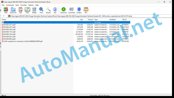
00 0291 027 2.pdf
00 0302 343 1.pdf
00 0302 565 2.pdf
00 0303 118 1.pdf
00 0303 154 2.pdf
00 0303 624 1.pdf
00 0305 863 0.pdf
CHP-numbers for connectors CLAAS HARNESS PARTS.pdf
00 0291 027 2.pdf:
MB OM460LAMB OM502LAMB OM906LAMB OM926LA
Table of contents
CCN explanation
CCN (CLAAS Component Number)
Electric systems standard
Overview
Hydraulic system standard
Overview
CCN (CLAAS Component Number)
Introduction
Safety rules
Safety and hazard precautions
Validity of manual
Validity of manual
01 Engine
0125 Injection / Fuel system
Injection / fuel system PLD
PLD injection system
Description of function
Pumping phases of plug-on pump
Description of function
Control of plug-on pump
Description of function
Classification of plug-on pumps
Example of a plug-on pump identification plate
Elements in example of plug-on pump identification plate
Fuel low-pressure measurement
Special tool
Preparation of fuel low-pressure measurement
Description of function
Measuring values, fuel low-pressure (downstream of fuel filter)
0155 Engine control
Diesel engine monitoring, diesel engine (MB TIER 3) TUCANO, JAGUAR
Measured values table
Description of function
Diesel engine monitoring, diesel engine (MB TIER 3) LEXION
Measured values table
Description of function
Diesel engine monitoring, diesel engine (MB TIER 4i) TUCANO, JAGUAR
Measured values table
Description of function
Limitation of torque in case of lack of urea
Description of function
Limitation of torque in case of insufficient urea quality
Description of function
Torque limitation after exceeding the time with system faults
Description of function
Diesel engine monitoring, diesel engine (MB TIER 4i) LEXION
Measured values table
Description of function
Limitation of torque in case of lack of urea
Description of function
Limitation of torque in case of insufficient urea quality
Description of function
Torque limitation after exceeding the time with system faults
Description of function
0165 Exhaust gas aftertreatment
Compressed-air system of MB TIER 4i (LEXION, TUCANO)
Description of function
Air dryer with integrated pressure controller
Description of function
Compressed air system MB TIER 4i (JAGUAR)
Description of function
Air dryer with integrated pressure controller
Description of function
SCR system – Urea heating and injection
Description of function
Combined filling level / urea temperature sensor
Description of function
Urea pump unit
Description of function
Reduction catalyst temperature sensors
Description of function
Dosing unit
Description of function
NOx sensor
Description of function
Combined intake air humidity and temperature sensor
Description of function
10 Electrical / Electronic equipment
1012 Modules / sensors
Module overview – MB (OM460LA, 502LA, 906LA, 926LA)
Key to diagram
Module A015 – Electronic engine control (ECM) – MB TIER 4i
Connector X1
Key to diagram
Module pin assignment, connector X1
Connector X2, sheet 1 of 2, 6-cylinder inline and V8 engine
Module pin assignment, connector X2 sheet 1 of 2
Connector X2, sheet 2 of 2, 6-cylinder inline engine
Module pin assignment, connector X2 sheet 2 of 2, 6-cylinder inline engine
Connector X2, sheet 2 of 2, V8 engine
Module pin assignment, connector X2 sheet 2 of 2, V8 engine
Module A017 – Engine adaptation module (ADM) – MB TIER 3
Key to diagram
Key to diagram
Module A017 – Engine adaptation module (ADM) – MB TIER 4i
Key to diagram
Key to diagram
Module A032 – Reduction catalyst (SCR) – MB TIER4i
Key to diagram
Key to diagram
Sensors MB OM460LA
Figure of sensors
Sensors on MB 502LA
Figure of sensors
Sensors on MB OM 906LA, OM 926LA
Figure of sensors
1085 Networks
BUS system (CAN) – engine and machine
Description of function
92 Diagnosis
Diagnosis by fault codes
9220 Error codes engine (J1939)
FMI failure code (Failure Mode Indicator)
FMI failure code (Failure Mode Indicator)
FMI 00 (Signal too high)
FMI 01 (Signal too low)
FMI 02 (Erratic signal)
FMI 03 (Voltage too high)
FMI 04 (Voltage too low)
FMI 05 (Current too low)
FMI 06 (Current too high)
FMI 07 (Mechanical failure)
FMI 08 (Abnormal frequency signal)
FMI 09 (Communication error)
FMI 10 (Rate of signal change too fast)
FMI 11 (multiple faults)
FMI 12 (ECU defective)
FMI 13 (Signal outside of calibration range)
FMI 16 (Parameter not available)
FMI 17 (ECU not responding)
FMI 18 (Power supply failure)
FMI 19 (Software conditions not met)
FMI 95 (no signal change)
FMI 96 (CAN Bus system defective)
FMI 97 (Erratic condition)
FMI 98 (Warning)
FMI 99 (Info)
Fault codes
Diesel engine J1939 (MB) fault code list
Description of function
00 0302 343 1.pdf:
PROFI CAM 3
Table of contents
General information
Marking of warnings and hazard prevention notes
First-aid measures
CCN explanation
CCN (CLAAS Component Number)
Electric system standard
Overview
Hydraulic system standard
Overview
CCN (CLAAS Component Number)
10 Electrical / Electronic equipment
1030 Board computer / Indicators
Camera system
Description of function
1097 Testing / Measuring / Adjusting
Testing / measuring / adjusting the PROFI CAM
Checking the fuse in the video channel select box (C102)
Testing the video camera connector (C055)
1098 Fault / remedy
Fault / remedy PROFI CAM
The video monitor (C101) shows no image or cannot be switched on (indicator light fails to light up)
Video monitor (C102) displays a blue image either permanently or temporarily
The video monitor image is blurred
Replacing the fuse in the video channel select box (C102)
Connection and connecting cable with video camera (C055)
00 0302 565 2.pdf:
Sensor system
Table of contents
CCN explanation
CCN (CLAAS Component Number)
Electric system standard
Overview
Hydraulic system standard
Overview
CCN (CLAAS Component Number)
Introduction
Safety rules
Safety and hazard information
10 Electrical / Electronic equipment
1097 Testing / Measuring / Adjusting
Test report of the angle sensor (0011780.x)
Application of test report
Required tools
Test report of the angle sensor (0011780.x)
Testing / Measuring / Adjusting of angle sensor (0011780.x)
1. Reason for test
2. Mechanical test of angle sensor
3. Electric test with CDS
4. Electric test with multimeter
5. Mechanical test of connecting cable
Completing the machine
Test report of position and speed sensors
Application of test report
Required tools
Sensor variants
Part numbers of speed sensors
Part number of position sensor
Test report of position and speed sensors
Testing / measuring / adjusting of position and speed sensors
1. Reason for test
2. Mechanical test
3. Electric test with CDS
4a. Installation dimensions
Check of installation dimension
Installation dimensions of gearbox speed sensor (0011 799.x) and cam speed sensor (0011 810.x)
Installation dimension of position sensor (0011 815.x)
4b. Installation position
Centring of sensor
Metal-free zone
5. Electric test with multimeter
Voltage measurement
Direction of rotation and speed sensor (0011 605.x)
Measured values table
6. Mechanical test of connecting cable
Completing the machine
Test report of the urea sensor (00 0773 207 x)
Application of test report
Required tools
Parts number of the urea sensor
Test report of the urea sensor
Testing / measuring / adjusting urea sensor
1. Reason for test
2. Mechanical test
3. Mechanical test of connecting cable
4. Electric test with multimeter
5. Component test with the CDS
00 0303 154 2.pdf:
JAGUAR 880 – 830
Table of contents
Introduction
Safety rules
Safety and hazard information
Validity of manual
Validity of manual
General information
Marking of warnings and hazard prevention notes
Safety routines
First-aid measures
CCN explanation
CCN (CLAAS Component Number)
Electric system standard
Overview
Hydraulic system standard
Overview
CCN (CLAAS Component Number)
01 Engine
0125 Injection / Fuel system
Additional fuel tank
Measured values table
Description of function
0150 Engine attachment parts
Starting the diesel engine, diesel engine speed adjustment (MTU TIER3)
Measured values table
Description of function
Starting the diesel engine, diesel engine speed adjustment (MTU Tier 4 / Stage V)
Measured values table
Description of function
0155 Engine control
Diesel engine monitoring, diesel engine
0165 Exhaust gas aftertreatment
Exhaust treatment system
03 Chassis
0315 Drive axle
Electro-hydraulic gearshift (EHS)
Measured values table
Description of function
0330 Rear steering drive axle
4-Trac system
Measured values table
Description of function
0335 Ground drive
Ground drive
Measured values table
Description of function
High-pressure sensors reference table (B097, B098)
0375 Cruise Control
CRUISE PILOT
Measured values table
Material feed height sensor setting (B124)
Description of function
04 Brake
0405 Service brake
Service brake
Description of function
0415 Parking brake
Parking brake
Description of function
0420 Trailer air brake
Compressed-air trailer brake system
Measured values table
Description of function
05 Steering
0505 Steering
Steering system
Measured values table
Description of function
0510 Automatic steering
AUTO PILOT / Sensing system
Measured values table
Description of function
AUTO PILOT / CAM PILOT
Measured values table
Description of function
CAM PILOT settings
Swath detection by CAM PILOT
Swath specifications
Field structure and conditions
Basic machine GPS steering system
Measured values table
Description of function
GPS steering system – EGNOS with CEBIS MOBILE
Description of function
GPS steering system – Omnistar HP with S7/S10 terminal
Description of function
GPS steering system – RTK with S7/S10 terminal
Description of function
GPS PILOT with RTK
GPS steering system – BASELINE HD with S7/S10 terminal
Description of function
09 Hydraulic system
0905 Hydraulic oil tank
Hydraulic oil tank
Key to diagram
0910 Pumps
Ground drive variable-displacement pump
Key to diagram
Constant-pressure pump (CPH)
Key to diagram
Description of function
CPH pump upon engine start
CPH pump when system pressure is reached
CPH pump when volume flow is requested by the system
Measuring and testing of constant-pressure pump
Test of constant-pressure pump (CPH)
ctions for test setup for testing of constant-pressure pump (CPH)
Testing and measuring the constant-pressure / low-pressure hydraulic system
Instructions for test setup for testing and measuring the constant-pressure / low-pressure hydraulic system
0915 Hydraulic lines
Pressure filter
Key to diagram
0920 Valves
Working hydraulics valve block
Key to diagram
Low-pressure hydraulics valve block – Working hydraulics
Key to diagram
Raise / lower front attachment valve block
Key to diagram
Pressure relief valve unit – ORBIS CAC (type 65x, 992, I5x)
Key to diagram
Reversing valve unit, front attachments
Key to diagram
ORBIS transport carriage valve block (type 659, 992, I52, I53)
Key to diagram
0925 Hydraulic Motors
Ground drive variable-displacement motor
Key to diagram
Reverse front attachment hydraulic motor
Key to diagram
Swinging upper discharge chute hydraulic motor
Key to diagram
Swinging upper discharge chute gear motor
Key to diagram
0980 Hydraulic circuit diagrams
Vehicle hydraulics circuit diagrams
SCM 01 – Constant pressure supply, ground drive
SCM 02 – Brake hydraulics, steering hydraulics
SCM 03 – Working hydraulics – with AUTO PILOT valve
SCM 04 – Low-pressure hydraulics
Front attachment hydraulics circuit diagrams
ORBIS 750
ORBIS 900
Key to diagram
Description of function
Key to diagram
Front attachment hydraulics circuit diagrams – ORBIS (type I61 – I66)
Front attachment hydraulics circuit diagrams – ORBIS (type I53 / I52 / 992 / 659)
ORBIS 750 with transport carriage
ORBIS 900 with transport carriage
Key to diagram
Description of function
Front attachment hydraulics circuit diagrams – PICK UP (type I36)
PICK UP (type I36)
Tipper hydraulic systems oil supply retrofit kit (0144415.0)
Description of function
Molasses system oil supply retrofit kit (0143 830.0)
10 Electrical / Electronic equipment
1010 Central electrics
Basic central terminal compartment
Basic central terminal compartment – Fuses and relays
Fuse assignment – Basic central terminal compartment
Relay assignment – Basic central terminal compartment
Connectors – Basic central terminal compartment
Connectors – Wiring loom assignment – Basic central terminal compartment
Roof central terminal compartment
Fuse assignment
Relay assignment
Electronic components
Roof central terminal compartment decal
Patch boards
Cab patch board 1 (inside)
Cab rear wall patch board 2 (outside)
1012 Modules / sensors
Module A006 – Automatic air conditioner (ACM)
Key to diagram
Key to diagram
Module A007 – Cab fan (CFC)
Key to diagram
Key to diagram
Module A009 – AUTO PILOT (ATP)
Key to diagram
Key to diagram
Module A015 – Electronic engine control (ECM) – MTU Tier 3
Key to diagram
Module pin assignment
Module A015 – Electronic engine control (ECM) – MTU TIER 4
Key to diagram
Module pin assignment
Module A015 – Electronic engine control (ECM) – MTU Stage V
Key to diagram
Module pin assignment
Module A017 – Engine adaptation (ADM) – MTU TIER 3
Key to diagram
Module pin assignment
Module A017 – Engine adaption (ADM) – MTU Tier 4
Key to diagram
Module pin assignment
Module A017 – Engine adaption (ADM) – MTU Stage V
Key to diagram
Module pin assignment
Module A032 – Reduction catalytic converter (SCR) – MTU TIER 4
Key to diagram
Module pin assignment
Module A032 – Reduction catalytic converter (SCR) – MTU Stage V
Key to diagram
Module pin assignment
Module A049 – ground drive (GDM)
Key to diagram
Key to diagram
Module A053 ISO BUS adaptation module
Key to diagram
Module A065 – GPS PILOT terminal
Key to diagram
Key to diagram
Module A069 – Vehicle base module (VBM)
Key to diagram
Key to diagram
Key to diagram
Key to diagram
Key to diagram
Key to diagram
Module A084 – Shear bar adjustment module (SBM)
Key to diagram
Key to diagram
Module A097 – Maize header (MCU)
Key to diagram
Module A099 – Additional control unit (ACU)
Key to diagram
Key to diagram
Key to diagram
Key to diagram
Key to diagram
Key to diagram
Module A100 – Multifunction arm rest module (MFA)
Key to diagram
Key to diagram
Module A100 – Multifunction arm rest module (MFA – 2/3)
Key to diagram
Key to diagram
Module A100 – Multifunction arm rest module (MFA – 3/3)
Key to diagram
Key to diagram
Module A104 – Work lights (WLP)
Key to diagram
Module A130 – Front attachment (FAM) (ORBIS)
Key to diagram
Module A159 – Universal communication module
Key to diagram
Key to diagram
Module A167 – Position control unit (PCU)
Key to diagram
Key to diagram
Module A190 – GPS PILOT terminal (ISO) (GPI)
Key to diagram
Key to diagram
F112 Immobiliser, NIR sensor
Key to diagram
Key to diagram
Module A209 CAN Ethernet gateway module
Key to diagram
Key to diagram
1030 Board computer / Indicators
Camera system
Description of function
Telematics
Description of function
Universal communication module A159 (UCM) – LED description
Status LED
Connection status LED
1035 Operation / Multifunction control lever
Road travel / fieldwork circuit
T signal
Measured values table
Description of function
1040 Yield measuring
Yield measuring with dry mass sensor
Measured values table
Material feed height sensor setting (B124)
Testing and measuring – conductivity / temperature measurement
Yield measuring with NIR contents sensor
Measured values table
Material feed height sensor setting (B124)
Contents sensor measuring principle
Content sensor system description
Contents sensor operating statuses
Content sensor measured value table (dry mass)
Contents sensor system behaviour under normal conditions
1080 Electrical circuit diagram
Introduction into circuit diagrams
Overview of designations
CLAAS wire marking
Wire colours
Power supply
Actuators
Actual value switch (output = 0 or 1)
Internal connections
Overview of CAN bus system
Communication
Standards
CLAAS Circuit Viewer
Electric system circuit diagrams (SCM)
SCM 005 Front attachment sectioning points
Key to diagram
SCM 010 Electric power supply MB T4
Key to diagram
SCM 015 Electric power supply MB Tier 3 / MB Stage V / MAN
Key to diagram
SCM 020 Basic central electrical system
Key to diagram
SCM 025 Basic central electrical system
SCM 035 Power supply of modules 12V / 24V Tier4 / MB Stage V
Key to diagram
SCM 050 Power supply of modules MB Tier 3
Key to diagram
SCM 055 Urea injection MB Tier 4
Key to diagram
SCM 060 Urea injection MB Stage V
Key to diagram
SCM 085 Power supply for module I
Key to diagram
SCM 090 Power supply of modules II
Key to diagram
SCM 100 Power supply of modules IV
Key to diagram
SCM 105 Power supply of sensors
SCM 110 Earth of sensors
SCM 115 Road travel
Key to diagram
SCM 120 Diesel engine speed adjustment / diesel engine monitoring
Key to diagram
SCM 125 CAN 0 (vehicle CAN)
Key to diagram
SCM 130 CAN 0 (vehicle CAN)
Key to diagram
SCM 135 CAN 1 (J1939 – CAN)
Key to diagram
SCM 140 CAN 2 (front attachment CAN)
Key to diagram
SCM 155 CAN 5 (ISO BUS)
Key to diagram
SCM 160 CAN 10 (chute CAN)
Key to diagram
SCM 165 UCM / CEG
Key to diagram
SCM 170 Main drive
Key to diagram
SCM 175 Fuel level
Key to diagram
SCM 180 Variable fan
Key to diagram
SCM 185 Machine monitoring
Key to diagram
SCM 190 Central lubrication system
Key to diagram
SCM 195 Ground drive
Key to diagram
Key to diagram
SCM 215 Air conditioner
Key to diagram
SCM 220 Raise/lower front attachment – cross levelling
Key to diagram
SCM 225 Auxiliary control unit 1 – Fold front attachment
Key to diagram
SCM 230 – Front attachment drive – Metal detector – Stone detector
Key to diagram
SCM 240 Upper discharge chute controller
Key to diagram
SCM 245 Corncracker
Key to diagram
SCM 250 DIRECT DISC
Key to diagram
SCM 255 – Shear bar sharpening
Key to diagram
SCM 260 Hitch – Gap adjustment – High tipper
Key to diagram
SCM 265 Four-wheel drive
Key to diagram
SCM 270 Brake system
Key to diagram
SCM 275 Brake light
Key to diagram
SCM 280 AUTO PILOT
Key to diagram
SCM 285 – Windscreen wiper – windscreen washer system
Key to diagram
SCM 290 Turn signal indicator system
Key to diagram
SCM 291 Direction indicator – validity: US
Key to diagram
SCM 295 Main lighting circuit – Parking light
Key to diagram
SCM 300 Drive lights
Key to diagram
SCM 305 Instrument lighting
Key to diagram
SCM 310 Maintenance lighting
Key to diagram
SCM 315 Sidefinder
Key to diagram
SCM 320 Work lights I. master circuit
Key to diagram
SCM 325 Work lights II. master circuit
Key to diagram
SCM 330 – Work lights II. master circuit Type 500
Key to diagram
SCM 335 Drive lights France
Key to diagram
SCM 340 Components fitted in the cab
Key to diagram
SCM 345 Compressed-air trumpet horn
Key to diagram
SCM 350 Mirror adjustment
Key to diagram
SCM 365 Service sockets
Key to diagram
SCM 370 Silage additive system
Key to diagram
SCM 375 Quantimeter / Auto Fill / NIR
Key to diagram
SCM 380 Rear camera
Key to diagram
SCM 385 Camera systems power supply from 2019
SCM 386 Camera systems from 2019
Key to diagram
SCM 390 Knife support
Key to diagram
SCM 400 Additional module (UBM)
SCM 405 T signal
Key to diagram
SCM 410 Earth supply
SCM 415 Earth supply
SCM 420 GPS1+ power supply
Key to diagram
SCM 425 GPS1+
Key to diagram
SCM 430 Task management
Key to diagram
Front attachment electric system circuit diagrams (SCM)
SCM 01 – JAGUAR interfaces
Key to diagram
SCM 02 – ORBIS
Key to diagram
Connectors
SCM 03 – DIRECT DISC
Key to diagram
SCM 04 – PICK-UP
Key to diagram
SCM 05 – Lighting
Key to diagram
Connectors
Front attachment electric system circuit diagrams – ORBIS (type I61 – I66) (SCM)
Front attachment electric system circuit diagrams – ORBIS (type I53 / I52 / 992 / 659) (SCM)
SCM 01 Power supply, CAN bus
Key to diagram
SCM 02 AUTO PILOT, CAC
Key to diagram
SCM 03 Fold ORBIS, transport carriage
Key to diagram
SCM 04 Transfer gearbox sensors
Key to diagram
SCM 09 Transfer gearbox touch arms
SCM 10 Module assignment (A130)
Key to diagram
PICK UP front attachment electric system circuit diagrams (I36 / I35) (SCM)
SCM 01 Power supply, CAN bus
Key to diagram
SCM 02 ACTIVE CONTOUR
Key to diagram
SCM 03 Reversing, roller type crop guard/touch wheels
Key to diagram
SCM 04 Lighting
1081 Overview of connectors
Connector database (chp CLAAS)
Example of representation of key numbers (CHP)
Connector representation (CHP)
1085 Networks
CAN BUS (MB Tier 3)
Description of function
CAN BUS (MB Tier 4)
Description of function
CAN Bus (MB Stage V)
Description of function
BUS systems (Ethernet) – basic machine
Description of function
1097 Testing / Measuring / Adjusting
Recording the external white balance / NIR content sensor
Recording an external white balance reference
Testing / measuring / adjusting the PROFI CAM
Checking the fuse in the video channel select box (C102)
Testing the video camera connector (C055)
1098 Fault / remedy
Fault / remedy NIR content sensor
Contents sensor system behaviour in case of fault
Contents sensor solution matrix for troubleshooting
DTC: 1459 Sapphire glass dirty
DTC: 1454 Spectrum implausible
DTC: 1450, 1461, 1462, 1467, 1468 lamp failed
DTC: 1472, 1473 Measured values permanently outside of specified range
DTC: 1451 Motor defective
DTC: 1463, 1464 Service life of the E146 or E147 lamp will end soon
DTC: 1453 Entire measuring head failed
DTC: 1460 No calibration detected
DTC: 1455 – 1458 Temperature outside the permitted range
DTC: 1469 Measuring head temperature sensor failed
DTC: 1470 Temperature sensor in the content sensor failed
DTC: 1471 Heating failed
DTC: 18cf, 18c0 Content sensor/dry matter measuring system failed
No fault messages from the system – but also no measured values displayed
Component and connector overview for solution matrix
Replacing the hardox plate with sapphire glass
Replacing the lamps (E146/E147)
User information for external white balance
External white balance
Fault / remedy PROFI CAM
The video monitor (C101) shows no image or cannot be switched on (indicator light fails to light up)
Video monitor (C102) displays a blue image either permanely or temporarily
The video monitor image is blurred
Replacing the fuse in the video channel select box (C102)
Connection and connecting cable with video camera (C055)
12 Cab / Operator’s platform
1230 Seat
Seat contact
Measured values table
Comfort seat
Description of nction
1240 Air condition
Automatic air conditioner
Measured values table
Description of function
Test menu:
Test menu operation
20 Crop feeding
2002 Front attachment
Raise / lower front attachment
Measured values table
Description of function
Circuit diagram
Pilot valve
Folding the front attachment in/out – ORBIS (type I61 – I66)
Measured values table
Description of function
Folding the front attachment in/out (ORBIS)
Measured values table
Description of function
ORBIS with transport carriage (type I61 – I65)
Measured values table
Description of function
System behaviour of ORBIS transport carriage in case of fault
ORBIS with transport carriage (type I53 / I52 / 992 / 659)
Measured values table
Description of function
System behaviour of ORBIS transport carriage in case of fault
Transport travel (active pitching dampening)
Measured values table
Description of function
Restricted ground speed when axle load is too high
Transport travel with carrier wheel cart – ORBIS (type 992 / 659)
Measured values table
Description of function
PICK UP / roller crop press, sensing wheels
Measured values table
Description of function
21 Feeder unit
2105 Feeder housing
Mechanical feeder drive
Measured values table
Description of function
System behaviour in case of fault
Metal detector
Stone detector
Stone detector fault – CEBIS symbol
2197 Inspecting / Measuring / Setting
Testing and measuring – Mechanical feeder
Testing and measuring – Metal detector function
Testing and measuring – Stone detector function
Stone detector fault – CEBIS symbol
Metal detector test protocol
Important information about the test protocol
Application of test protocol
Tools required
Preparation for creating the test protocol
Test protocol
Digital magnetic box
Stone detector test protocol
Important information about the test protocol
Application of test protocol
Tools required
Preparation for creating the test protocol
Test protocol
Testing / measuring of metal detector
Preparing the measurement
Performing the measurement
Testing and measuring – stone detector
Testing sequence
Evaluation
2198 Fault / Remedy
Metal detector check list for fault analysis
26 Ground guidance
2605 AUTO CONTOUR
CONTOUR – ORBIS (I61 – I66)
Measured values table
Description of function
Measured values table
Description of function
AUTO CONTOUR (CAC) / manual cross levelling – ORBIS (I61 – I66)
Measured values table
Description of function
AUTO CONTOUR (CAC) / manual cross levelling
Measured values table
Description of function
ACTIVE CONTOUR – PICK UP
Measured values table
Description of function
44 Chopping
4415 Shear bar
Shear bar (adjustment)
Measured values table
Description of function
Shear bar clearance sensors (B084 / B085)
Normal counter behaviour
Counter behaviour when the knife condition is incorrectly set
Fault display
4420 Cutting cylinder
Chopper unit (main drive)
Measured values table
Description of function
Hydraulic circuit diagram – Engaging and decelerating the main drive
Description of function – Engaging and decelerating the main drive
Main drive engaging test
Main drive shut-down test
Instructions for test-set-up (Engaging the main drive / disengaging the main drive)
4425 Knife sharpener
Sharpening the cutting cylinder
Measured values table
Sharpening operation
Key to diagram
Key to diagram
Description of function
4498 Fault / Remedy
Deactivating automatic main drive shut-down
Deactivating automatic inspection and maintenance shut-down
Prerequisites for the diagnostics mode
Problem / remedy – shear bar
Solution matrix for troubleshooting on the shear bar adjustment
DTC 2336 Right shear bar adjustment motor no reaction
DTC 2337 Left shear bar adjustment motor no reaction
DTC 2342 Left shear bar adjusting unit disabled. Repair the mechanism. Re-enter the knife condition.
DTC 2343 Right shear bar adjusting unit disabled. Repair the mechanism. Re-enter the knife condition.
DTC 233f Mechanical tension in the shear bar adjustment unit too high
DTC 2338 Knock sensor signal faulty
DTC 233e Insufficient shear bar clearance selected in CEBIS. Increase the clearance. The adjustment procedure must be repeated.
DTC 2352 Shear bar lever solenoid coil defective
DTC 2353 Shear bar lever solenoid coil defective
DTC 2354 Shear bar lever solenoid coil defective
DTC 2356 Shear bar lever hydraulic clamping pressure sensor signal defective
DTC 2357 Shear bar lever hydraulic clamping pressure sensor signal defective
DTC 2358 Hydraulic pressure outside the permitted range during an active adjustment procedure – adjustment procedure aborted
Error 01: Knocking detected despite excessive shear bar gap
Error 02: Adjusting procedure is not reproducible. Differing shear bar gaps after several adjustments. One screwing-down on the right, one screwing-down on the left. Different gaps at the same sensitivity.
Error 03: Adjusting procedure takes too long (depending on the real shear bar gap). Limit value for types 498 / 499 / 502: more than 3 min.
Error 04: The shear bar moves away from the
John Deere Repair Technical Manual PDF
John Deere Repair Technical Manual PDF
John Deere Application List Component Technical Manual CTM106819 24AUG20
John Deere Repair Technical Manual PDF
John Deere Parts Catalog PDF
John Deere Harvesters 8500 and 8700 Parts Catalog CPCQ24910 Spanish
John Deere Repair Technical Manual PDF
John Deere Repair Technical Manual PDF
John Deere Repair Technical Manual PDF
John Deere 18-Speed PST Repair Manual Component Technical Manual CTM168 10DEC07
John Deere Repair Technical Manual PDF
John Deere Repair Technical Manual PDF
John Deere POWERTECH E 4.5 and 6.8 L Diesel Engines TECHNICAL MANUAL 25JAN08

