Claas Cougar 1400 Mahtechnik (788) Mower Technical System EN
$300.00
- Model: Cougar 1400 Mahtechnik (788) Mower
- Type Of Manual: Technical System
- Language: EN
- Format: PDF(s)
- Size: 37.0 MB
File List:
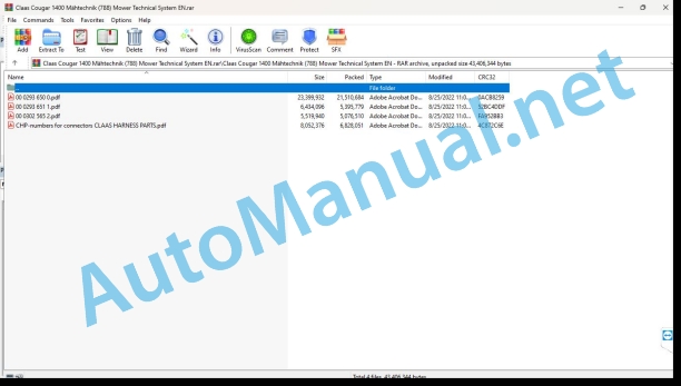
00 0293 650 0.pdf
00 0293 651 1.pdf
00 0302 565 2.pdf
CHP-numbers for connectors CLAAS HARNESS PARTS.pdf
00 0293 650 0.pdf:
Table of Content
1 Overall hydraulic system
Hydraulic circuit diagram
Overall circuit diagram
Designations
PFC pump – compensation valve
Designations
Description of function
PFC pump – initial position (Engine OFF)
Designations
Description of
PFC pump – low-pressure standby
Designations
Description of
PFC pump – pump changes to delivery mode
Designations
Description of
PFC pump – constant volume flow
Designations
Description of
PFC pump – downstroking
Designations
Description of
PFC pump – maximum pressure limitation (pressure relief valve function)
Designations
Description of
2 Steering hydraulics
System concept
Description
Emergency steering mode
Hydraulic circuit diagram
Designations
Function
The motor axle steered by the Orbitrol steering unit
Hydraulic circuit diagram
Designations
Function
Fully electronic steering mode (steer-by-wire)
Hydraulic circuit diagram
Designations
Function
Steering hydraulics valve block
Graphics
Designations
3 Working hydraulics
Hydraulic circuit diagram
Working hydraulics circuit diagram
Designations
Working hydraulics valve block
Graphics
Designations
Side arm solenoid valve
Graphics
Designations
Discription of function
Front power lift solenoid valve, front mower unit
Graphics
Designations
Discription of function
Constant-pressure system valve block
Graphics
Designations
Upper link, safety frame solenoid valve
Graphics
Designations
Discription of function
Cab rotation solenoid valve
Graphics
Designations
Discription of function
Constant-pressure system solenoid valve
Graphics
Designations
Description of function
Testing and measuring
4 Low-pressure hydraulic system
Hydraulic circuit diagram
Low-pressure hydraulic system circuit diagram
Designations
Low-pressure hydraulic system valve block
Graphics
Designations
Discription of function
4-Trac solenoid valve, differential lock, gearbox shifting, drive clutch
Designations
Discription of function
Testing and measuring
Designations
5 Ground drive hydraulics
Hydraulic circuit diagram
Ground drive hydraulics circuit diagram
Designations
Ground drive control
Ground drive variable-displacement pump (211)
Additional feed and ground drive cooling
Ground drive forward/reverse solenoid coil, shut-off valve
Ground drive variable-displacement motor
Testing and measuring
Pressure testing using the signals from the high-pressure sensors B97, B98
Measured value table
6 Location of components
Overview
Main sub-assemblies (I to XI)
Component grid (DIN A3)
00 0293 651 1.pdf:
Table of Content
1 Introduction
Structure of electrical documentation
Circuit diagram
Grid co-ordinates
Interconnection list
CLAAS standard:
2 Central terminal compartment
Overview
View with cover folded up
View with central terminal unit folded up
Plug-in contact
Electronic components
3 Modules
Module representation
Overview 1
Overview 2
Module assignment
Module A15 – Electronic engine control DC
Module A17 – Engine adaptation (ADM)
Module A49 – Ground drive module
Module A52 – MFG (Multi-function handle)
Module A55 Electro-hydraulic steering (EHL) connector X1
Module A55 Electro-hydraulic steering (EHL) connector X2
Module A59-1 Valve control, right (VCU)
Module A59-2 Valve control, left (VCU)
Module A68 Mower unit control module (MCM) 42-pin connector X1
Module A68 Mower unit control module (MCM) 70-pin connector X2
Module A69 VBM 42-pin connector X1
Module A69 VBM 70-pin connector X2
4 Circuit diagrams
01a Main power supply, diesel engine electric starting motor
Circuit diagram (DIN A3)
Key to diagram
02a Diesel engine speed adjustment / Fan control
Circuit diagram (DIN A3)
Key to diagram
03a Diesel engine cut-off system
Circuit diagram (DIN A3)
Key to diagram
04a Road travel circuit, constant-pressure circuit, all-wheel drive circuit
Circuit diagram (DIN A3)
Key to diagram
05a Terminal
Circuit diagram (DIN A3)
Key to diagram
06a CAN BUS, module power supply
Circuit diagram (DIN A3)
Key to diagram
07a Centre mower unit drive circuit
Circuit diagram (DIN A3)
Key to diagram
08a Front mower unit PTO shaft circuit
Circuit diagram (DIN A3)
Key to diagram
12a Multifunction handle
Circuit diagram (DIN A3)
Key to diagram
A52 Multifunction handle module
13a Front mower units management
Circuit diagram (DIN A3)
Key to diagram
14a Centre mower units management
Circuit diagram (DIN A3)
Key to diagram
15a Swath control (reserved)
Circuit diagram (DIN A3)
Key to diagram
26a Machine monitoring
Circuit diagram (DIN A3)
Key to diagram
27a External sensor monitoring, laser steering reserved
Circuit diagram (DIN A3)
Key to diagram
28a EHL, cab position detection, special steering programs enable
Circuit diagram (DIN A3)
Key to diagram
30a Warning beacon
Circuit diagram (DIN A3)
Key to diagram
33a Cab rotation
Circuit diagram (DIN A3)
Key to diagram
36a Turn indicator system (Europe)
Circuit diagram (DIN A3)
Key to diagram
36b Turn indicator system (USA)
Circuit diagram (DIN A3)
Key to diagram
37a Windscreen wiper, Windscreen washer
Circuit diagram (DIN A3)
Key to diagram
38a Compressor-type air conditioner
Circuit diagram (DIN A3)
Key to diagram
39a Operator’s seat
Circuit diagram (DIN A3)
Key to diagram
40a Additional sockets
Circuit diagram (DIN A3)
Key to diagram
41a Drive management, parking brake, cab position, differential lock
Circuit diagram (DIN A3)
Key to diagram
42a Limp Home
Circuit diagram (DIN A3)
Key to diagram
43a Electronic ground drive, cab position detection
Circuit diagram (DIN A3)
Key to diagram
44a Transmission control
Circuit diagram (DIN A3)
Key to diagram
45a Lighting main circuit, taillight, position light
Circuit diagram (DIN A3)
Key to diagram
46a Low beam, high beam, low beam changeover switch
Circuit diagram (DIN A3)
Key to diagram
47a Worklights I
Circuit diagram (DIN A3)
Key to diagram
49a Transmission control
Circuit diagram (DIN A3)
Key to diagram
50a Instrument lighting, broadcast radio, mirror adjustment
Circuit diagram (DIN A3)
Key to diagram
5 Diagnosis
Diagnosis according to fault code
Fault code CCN (CLAAS Component Number)
Circuit diagram structure
FMI fault code (fault mode indicator)
6 Location of components
Overview (DIN A3)
00 0302 565 2.pdf:
Sensor system
Table of contents
CCN explanation
CCN (CLAAS Component Number)
Electric system standard
Overview
Hydraulic system standard
Overview
CCN (CLAAS Component Number)
Introduction
Safety rules
Safety and hazard information
10 Electrical / Electronic equipment
1097 Testing / Measuring / Adjusting
Test report of the angle sensor (0011780.x)
Application of test report
Required tools
Test report of the angle sensor (0011780.x)
Testing / Measuring / Adjusting of angle sensor (0011780.x)
1. Reason for test
2. Mechanical test of angle sensor
3. Electric test with CDS
4. Electric test with multimeter
5. Mechanical test of connecting cable
Completing the machine
Test report of position and speed sensors
Application of test report
Required tools
Sensor variants
Part numbers of speed sensors
Part number of position sensor
Test report of position and speed sensors
Testing / measuring / adjusting of position and speed sensors
1. Reason for test
2. Mechanical test
3. Electric test with CDS
4a. Installation dimensions
Check of installation dimension
Installation dimensions of gearbox speed sensor (0011 799.x) and cam speed sensor (0011 810.x)
Installation dimension of position sensor (0011 815.x)
4b. Installation position
Centring of sensor
Metal-free zone
5. Electric test with multimeter
Voltage measurement
Direction of rotation and speed sensor (0011 605.x)
Measured values table
6. Mechanical test of connecting cable
Completing the machine
Test report of the urea sensor (00 0773 207 x)
Application of test report
Required tools
Parts number of the urea sensor
Test report of the urea sensor
Testing / measuring / adjusting urea sensor
1. Reason for test
2. Mechanical test
3. Mechanical test of connecting cable
4. Electric test with multimeter
5. Component test with the CDS
CHP-numbers for connectors CLAAS HARNESS PARTS.pdf:
CLAAS HARNESS PARTS
Table of contents
10 Electrical / Electronic equipment
1081 Overview of connectors
CLAAS HARNESS PARTS (CHP)
John Deere Repair Technical Manual PDF
John Deere Repair Technical Manual PDF
John Deere Transmission Control Unit Component Technical Manual CTM157 15JUL05
John Deere Repair Technical Manual PDF
John Deere Repair Technical Manual PDF
John Deere Repair Technical Manual PDF
John Deere 16, 18, 20 and 24HP Onan Engines Component Technical Manual CTM2 (19APR90)
John Deere Repair Technical Manual PDF
John Deere DF Series 150 and 250 Transmissions (ANALOG) Component Technical Manual CTM147 05JUN98
John Deere Repair Technical Manual PDF
New Holland Service Manual PDF
John Deere Repair Technical Manual PDF

