Claas Disco 3500 Tc (F52) Mower Operator Manual EN
$50.00
- Model: Disco 3500 Tc (F52) Mower
- Type Of Manual: Operator Manual
- Language: EN
- Format: PDF(s)
- Size: 37.1 MB
File List:
00 0295 391 2.pdf
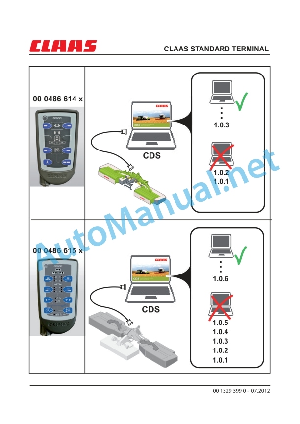
00 1329 399 0.pdf
00 2348 408 0.pdf
00 2348 427 0.pdf
00 0295 391 2.pdf:
Contents
1 Machine description
1.1 DISCO 3900 TC; 3500 TC / TRC; 3100 TC / TRC 9
1.1.1 Designations 9
1.2 DISCO 3100 TC AS 11
1.2.1 Designations 11
2 Introduction
2.1 General Information 13
2.1.1 Using the manual 13
2.1.2 Validity of manual 14
2.2 Identification plates and identification numbers 15
2.2.1 Spare parts and technical questions 15
2.2.2 Identification plate 16
3 Safety
3.1 Basic safety instructions 17
3.1.1 General safety information 17
3.1.2 Intended use 17
3.1.3 Reasonable foreseeable misuse 18
3.1.4 Directives, statutes and standards 18
3.1.5 Technical condition 19
3.1.6 Occupational safety 19
3.1.7 Hydraulics 21
3.1.8 Safety features on the machine 22
3.1.9 What to do in the event of hazardous situations and accidents 22
3.1.10 Decommissioning and disposal 23
3.2 Warning and hazard signs 24
3.2.1 Labels 24
3.3 Safety decals 25
3.3.1 General instructions for warning signs 25
3.3.2 Placement on the machine 26
4 Specifications
4.1 DISCO 3900 TC – Model F53 33
4.1.1 Dimensions and weight 33
4.1.2 Requirements for the tractor 34
4.1.3 Design 34
4.1.4 Tyres 34
4.1.5 Noise level 35
4.2 DISCO 3500 TC / DISCO 3500 TRC – Model F52 36
4.2.1 Dimensions and weight 36
4.2.2 Requirements for the tractor 37
4.2.3 Design 37
4.2.4 Tyres 37
4.2.5 Noise level 38
4.3 DISCO 3100 TC / DISCO 3100 TRC – Model F51 39
4.3.1 Dimensions and weight 39
4.3.2 Requirements for the tractor 40
4.3.3 Design 40
4.3.4 Tyres 40
4.3.5 Noise level 41
4.4 DISCO 3100 TC AS – Model F51 42
4.4.1 Dimensions and weight 42
4.4.2 Requirements for the tractor 43
4.4.3 Design 43
4.4.4 Tyres 43
4.4.5 Noise level 44
5 Prior to initial operation
5.1 General information 45
5.1.1 Checklist for commissioning 45
5.2 Adaptation to the machine 46
5.2.1 Universal drive shaft – check length 46
5.2.2 Universal drive shaft – adjusting length 47
5.2.3 Mounting universal drive shaft on machine 48
5.2.4 Adjusting the lateral offset 50
5.3 Accessories 53
5.3.1 Crop spreader (G03 0010) 53
5.3.2 Swathing plate extension (G03 0060) 53
5.3.3 High-cut skids (B03 0020) 53
5.3.4 Skid extensions (C03 0030) 54
5.3.5 Hydraulic connection for tractor (R03 0030) 54
6 Before putting the machine into operation
6.1 General information 55
6.1.1 Check list for putting into operation 55
7 Attaching / detaching machine
7.1 Hitching the machine 56
7.1.1 General instructions 56
7.1.2 Connecting the hitch bracket 57
7.1.3 Raising the prop stand 57
7.1.4 Fitting the universal drive shaft 58
7.1.5 Coupling hydraulic hose lines 60
7.1.6 Connecting the power supply 65
7.1.7 Cross conveyor belt control terminal 65
7.2 Unhitching the machine 66
7.2.1 General instructions 66
7.2.2 Lowering the prop stand 66
7.2.3 Disconnecting the power supply 67
7.2.4 Cross conveyor belt control terminal 67
7.2.5 Decoupling hydraulic hose lines 68
7.2.6 Removing universal drive shaft 72
7.2.7 Unhitching headstock 72
8 Driving and Transport
8.1 General information 73
8.1.1 Road travel 73
8.1.2 Field driving 76
8.1.3 Handling 76
8.2 Transport position 77
8.2.1 Folding down safety devices 77
8.2.2 Lifting the mower unit 78
8.2.3 Swinging to transport position 79
8.2.4 Lowering the cross conveyor belt to working and transport position 80
8.3 Loading machine 81
8.3.1 Loading / unloading machine 81
9 Setup for work use
9.1 Working position 82
9.1.1 Folding safety devices 82
9.1.2 Adjusting the hitch bracket 83
9.1.3 Adjusting the mower head load relief 83
9.1.4 Adjusting the cutting height 85
9.2 Conditioner of DISCO 3900 TC / 3500 TC / 3100 TC / TC AS 86
9.2.1 Conditioner speed 86
9.2.2 Chicane plate 86
9.2.3 Swathing plates 87
9.2.4 Crop spreader 88
9.3 DISCO 3500 TRC / 3100 TRC conditioner 89
9.3.1 Swathing plates 89
9.3.2 Mowing without conditioner effect 89
9.4 Cross conveyor belt of DISCO 3100 TC AS 91
9.4.1 Adjusting the discharge flap 91
9.4.2 Cross conveyor belt – Adjusting the throwing distance 92
10 Working
10.1 Working in the field 93
10.1.1 General instructions 93
10.1.2 Swinging into working position 95
10.1.3 Lowering the mower unit 96
10.2 Mowing 97
10.2.1 Putting the machine into operation 97
10.2.2 Mowing methods 98
10.2.3 Turning area position 99
10.2.4 Instructions for mowing 100
10.2.5 Difficult conditions of use 101
10.2.6 Recommendation for environmental protection 101
10.3 Mowing with cross conveyor belt DISCO 3100 TC AS 103
10.3.1 Putting the machine into operation 103
10.3.2 Lifting / lowering the cross conveyor belt 104
10.3.3 Starting / stopping the cross conveyor belt 104
10.3.4 Mowing methods 105
11 Maintenance
11.1 General warning signs 107
11.1.1 Bolts 107
11.1.2 Lubrication 107
11.1.3 Wheels / tyres 108
11.1.4 Hydraulic system 109
11.1.5 Electrical system 109
11.1.6 Protective guards 110
11.1.7 Parts 110
11.1.8 Unbalance 110
11.1.9 Cleaning and care 111
11.1.10 Winter storage recommendations 112
11.2 Maintenance schedule 113
11.2.1 Service intervals 113
11.3 Lubricants 115
11.3.1 Lubricants chart 115
11.4 Gearbox / clutch / universal drive shaft 118
11.4.1 Main gearbox 119
11.4.2 Transfer gearbox 122
11.4.3 Angle drive 126
11.4.4 Maintaining universal drive shaft 128
11.4.5 Friction clutch 129
11.4.6 Venting the friction clutch 129
11.4.7 Replacing the friction discs 130
11.5 Transport chassis 131
11.5.1 Wheels and tyres 131
11.5.2 Wheel change 132
11.6 Hitch 133
11.6.1 Adjusting the hitch bracket pressure springs 133
11.7 Hydraulics 134
11.7.1 Hydraulic system 134
11.7.2 Hydraulic hose lines 135
11.7.3 Accumulator 136
11.7.4 Tensioning the hydraulic pump drive belt 137
11.7.5 Replacing the drive belt hydraulic pump 137
11.7.6 Cross conveyor belt hydraulic oil 138
11.8 Mowing unit 139
11.8.1 Mower head gearbox 140
11.8.2 Mower knife box 143
11.8.3 Replacing the knives 144
11.8.4 Knife holder 150
11.8.5 Maintaining the cutting disc 152
11.8.6 Replacing the cutting discs 153
11.8.7 Installing the pinion units 154
11.8.8 Adjusting the safety guard 155
11.8.9 Anti-wrapping guard 156
11.9 Crop processing 157
11.9.1 Tensioning the conditioner drive belt 157
11.9.2 Changing conditioner drive belts 157
11.9.3 Installing/removing the conditioner tines DISCO 3900 TC / 3500 TC / 3100 TC 159
11.9.4 DISCO 3500 TRC / 3100 TRC conditioner rollers 160
11.10 Crop discharge 162
11.10.1 Adjusting the cross conveyor belt 162
11.11 Attachment parts/machine body 166
11.11.1 Adjusting the suspended frame tension springs 166
11.12 Problems and remedies 167
12 Lubrication chart
12.1 Lubrication points 170
12.1.1 Lubricants 170
12.1.2 Lubrication intervals 171
12.1.3 Lubrication points – 8 h 174
12.1.4 Lubrication points – 20 h 175
12.1.5 Lubrication points – 100 h 178
12.1.6 Lubrication points – 250 h 179
1 Machine description
1.1 DISCO 3900 TC; 3500 TC / TRC; 3100 TC / TRC
1.1.1 Designations
1.2 DISCO 3100 TC AS
1.2.1 Designations
2 Introduction
2.1 General Information
2.1.1 Using the manual
Texts and figures
Document structure based on subassemblies
Search and find
Technical specifications
Directions
2.1.2 Validity of manual
2.2 Identification plates and identification numbers
2.2.1 Spare parts and technical questions
2.2.2 Identification plate
3 Safety
3.1 Basic safety instructions
3.1.1 General safety information
3.1.2 Intended use
3.1.3 Reasonable foreseeable misuse
3.1.4 Directives, statutes and standards
3.1.5 Technical condition
3.1.6 Occupational safety
3.1.7 Hydraulics
3.1.8 Safety features on the machine
3.1.9 What to do in the event of hazardous situations and accidents
3.1.10 Decommissioning and disposal
3.2 Warning and hazard signs
3.2.1 Labels
3.3 Safety decals
3.3.1 General instructions for warning signs
3.3.2 Placement on the machine
00 0515 130 0 (2)
00 0515 134 0 (33)
00 0480 462 0 (1)
00 0514 899 0 (8)
00 0515 380 0 (21)
00 0516 039 0 (22)
00 0515 139 1 (50)
00 0514 799 0 (6)
00 0516 038 0 (21)
00 0516 052 0 (25)
00 0514 825 0 (32)
4 Specifications
4.1 DISCO 3900 TC – Model F53
4.1.1 Dimensions and weight
4.1.2 Requirements for the tractor
4.1.3 Design
4.1.4 Tyres
4.1.5 Noise level
A-valuated equivalent permanent sound pressure level
Measuring method
4.2 DISCO 3500 TC / DISCO 3500 TRC – Model F52
4.2.1 Dimensions and weight
4.2.2 Requirements for the tractor
4.2.3 Design
4.2.4 Tyres
4.2.5 Noise level
A-valuated equivalent permanent sound pressure level
Measuring method
4.3 DISCO 3100 TC / DISCO 3100 TRC – Model F51
4.3.1 Dimensions and weight
4.3.2 Requirements for the tractor
4.3.3 Design
4.3.4 Tyres
4.3.5 Noise level
A-valuated equivalent permanent sound pressure level
Measuring method
4.4 DISCO 3100 TC AS – Model F51
4.4.1 Dimensions and weight
4.4.2 Requirements for the tractor
4.4.3 Design
4.4.4 Tyres
4.4.5 Noise level
A-valuated equivalent permanent sound pressure level
Measuring method
5 Prior to initial operation
5.1 General information
5.1.1 Checklist for commissioning
5.2 Adaptation to the machine
5.2.1 Universal drive shaft – check length
Universal drive shaft – shortest operating position
Universal drive shaft – longest operating position
5.2.2 Universal drive shaft – adjusting length
Universal drive shaft without seal on the outer profile tube
Universal drive shaft with seal on the outer profile tube
5.2.3 Mounting universal drive shaft on machine
Locking pin – lock
Draw lock
5.2.4 Adjusting the lateral offset
Adjusting the hydraulic cylinder length
Hydraulic cylinder alignment position
5.3 Accessories
5.3.1 Crop spreader (G03 0010)
DISCO 3900 TC
DISCO 3500 TC
DISCO 3100 TC
5.3.2 Swathing plate extension (G03 0060)
DISCO 3900 TC
5.3.3 High-cut skids (B03 0020)
5.3.4 Skid extensions (C03 0030)
DISCO 3900 TC
DISCO 3500 TC / TRC
DISCO 3100 TC / TRC / TC AS
5.3.5 Hydraulic connection for tractor (R03 0030)
6 Before putting the machine into operation
6.1 General information
6.1.1 Check list for putting into operation
7 Attaching / detaching machine
7.1 Hitching the machine
7.1.1 General instructions
7.1.2 Connecting the hitch bracket
7.1.3 Raising the prop stand
7.1.4 Fitting the universal drive shaft
Wide angle constant-velocity joint
7.1.5 Coupling hydraulic hose lines
Hydraulic hose lines – Lifting
Hydraulic hoses – swivelling
Hydraulic hose line – Load relief
Hydraulic hose – cross conveyor belt
7.1.6 Connecting the power supply
7.1.7 Cross conveyor belt control terminal
7.2 Unhitching the machine
7.2.1 General instructions
7.2.2 Lowering the prop stand
7.2.3 Disconnecting the power supply
7.2.4 Cross conveyor belt control terminal
7.2.5 Decoupling hydraulic hose lines
Hydraulic hose line – Load relief
Hydraulic hoses – swivelling
Hydraulic hose lines – Lifting
Hydraulic hose – cross conveyor belt
7.2.6 Removing universal drive shaft
Locking pin – lock
Draw lock
7.2.7 Unhitching headstock
8 Driving and Transport
8.1 General information
8.1.1 Road travel
Marking the machine for road travel
8.1.2 Field driving
8.1.3 Handling
8.2 Transport position
8.2.1 Folding down safety devices
8.2.2 Lifting the mower unit
8.2.3 Swinging to transport position
8.2.4 Lowering the cross conveyor belt to working and transport position
8.3 Loading machine
8.3.1 Loading / unloading machine
9 Setup for work use
9.1 Working position
9.1.1 Folding safety devices
9.1.2 Adjusting the hitch bracket
9.1.3 Adjusting the mower head load relief
9.1.4 Adjusting the cutting height
9.2 Conditioner of DISCO 3900 TC / 3500 TC / 3100 TC / TC AS
9.2.1 Conditioner speed
DISCO 3900 TC:
DISCO 3500 TC / 3100 TC / 3100 TC AS:
9.2.2 Chicane plate
9.2.3 Swathing plates
9.2.4 Crop spreader
9.3 DISCO 3500 TRC / 3100 TRC conditioner
9.3.1 Swathing plates
9.3.2 Mowing without conditioner effect
9.4 Cross conveyor belt of DISCO 3100 TC AS
9.4.1 Adjusting the discharge flap
9.4.2 Cross conveyor belt – Adjusting the throwing distance
10 Working
10.1 Working in the field
10.1.1 General instructions
10.1.2 Swinging into working position
10.1.3 Lowering the mower unit
10.2 Mowing
10.2.1 Putting the machine into operation
10.2.2 Mowing methods
10.2.3 Turning area position
10.2.4 Instructions for mowing
10.2.5 Difficult conditions of use
10.2.6 Recommendation for environmental protection
10.3 Mowing with cross conveyor belt DISCO 3100 TC AS
10.3.1 Putting the machine into operation
10.3.2 Lifting / lowering the cross conveyor belt
10.3.3 Starting / stopping the cross conveyor belt
10.3.4 Mowing methods
11 Maintenance
11.1 General warning signs
11.1.1 Bolts
11.1.2 Lubrication
11.1.3 Wheels / tyres
11.1.4 Hydraulic system
11.1.5 Electrical system
11.1.6 Protective guards
11.1.7 Parts
11.1.8 Unbalance
11.1.9 Cleaning and care
11.1.10 Winter storage recommendations
11.2 Maintenance schedule
11.2.1 Service intervals
11.3 Lubricants
11.3.1 Lubricants chart
11.4 Gearbox / clutch / universal drive shaft
11.4.1 Main gearbox
Top gearbox
Lower gearbox
Cleaning the breather valve
Checking the oil level
Topping up oil
Draining / changing the oil
11.4.2 Transfer gearbox
Top gearbox
Lower gearbox
Cleaning the breather valve
Checking the oil level
Topping up oil
Draining / changing the oil
11.4.3 Angle drive
Checking the oil level
Topping up oil
Draining / changing the oil
Cleaning the vent valve
11.4.4 Maintaining universal drive shaft
General information about universal drive shafts
11.4.5 Friction clutch
11.4.6 Venting the friction clutch
11.4.7 Replacing the friction discs
11.5 Transport chassis
11.5.1 Wheels and tyres
11.5.2 Wheel change
11.6 Hitch
11.6.1 Adjusting the hitch bracket pressure springs
11.7 Hydraulics
11.7.1 Hydraulic system
11.7.2 Hydraulic hose lines
11.7.3 Accumulator
Check pre-loading pressure
11.7.4 Tensioning the hydraulic pump drive belt
11.7.5 Replacing the drive belt hydraulic pump
11.7.6 Cross conveyor belt hydraulic oil
Checking the oil level
Topping up oil
Draining / changing the oil
11.8 Mowing unit
11.8.1 Mower head gearbox
Checking the oil level
Topping up oil
Draining / changing the oil
11.8.2 Mower knife box
11.8.3 Replacing the knives
Mower knife quick change system
11.8.4 Knife holder
11.8.5 Maintaining the cutting disc
Cleaning the drain opening
Checking the wear bars
11.8.6 Replacing the cutting discs
11.8.7 Installing the pinion units
11.8.8 Adjusting the safety guard
Front safety guard holder
Safety guard holder, left /right
11.8.9 Anti-wrapping guard
11.9 Crop processing
11.9.1 Tensioning the conditioner drive belt
11.9.2 Changing conditioner drive belts
11.9.3 Installing/removing the conditioner tines DISCO 3900 TC / 3500 TC / 3100 TC
11.9.4 DISCO 3500 TRC / 3100 TRC conditioner rollers
Adjusting the tension springs
Adjusting synchronous running
Adjusting the roller clearance
11.10 Crop discharge
11.10.1 Adjusting the cross conveyor belt
11.11 Attachment parts/machine body
11.11.1 Adjusting the suspended frame tension springs
11.12 Problems and remedies
12 Lubrication chart
12.1 Lubrication points
12.1.1 Lubricants
12.1.2 Lubrication intervals
12.1.3 Lubrication points – 8 h
12.1.4 Lubrication points – 20 h
12.1.5 Lubrication points – 100 h
12.1.6 Lubrication points – 250 h
00 2348 408 0.pdf:
CEMIS 100
Table of contents
1 Introduction
1.1 General information
1.1.1 Validity of the manual
1.1.2 Information about this Operator’s Manual
1.1.3 Symbols and notes
1.2 Intended use
1.2.1 Intended use
1.2.2 Reasonably foreseeable misuse
2 Safety
2.1 Safety rules
2.1.1 General safety and accident prevention regulations
2.1.2 Interaction between terminal and machine or tractor
2.1.3 Electrocution by electrical system
3 Product description
3.1 Overview and method of operation
3.1.1 Overview of CEMIS 100
3.1.2 Function principle of CEMIS 100
3.2 Identification plates and identification numbers
3.2.1 Spare parts and technical questions
3.2.2 Identification plate of CEMIS 100
4 Operating and display elements
4.1 CEMIS 100
4.1.1 User interface for LINER
4.1.2 User interface for ROLLANT
4.1.3 User interface for UNIWRAP
5 Technical specifications
5.1 CEMIS 100
5.1.1 Specification
6 Operation
6.1 CEMIS 100
6.1.1 Operating the CEMIS 100
6.1.2 Switching CEMIS 100 on
6.1.3 Switching CEMIS 100 off
7 Maintenance
7.1 CEMIS 100
7.1.1 Daily
8 Putting out of operation and disposal
8.1 General information
8.1.1 Removal from service and disposal
9 Technical terms and abbreviations
9.1 Terms and explanations
9.1.1 Technical words
9.1.2 Abbreviations
00 2348 427 0.pdf:
CEMIS 700
Table of contents
1 Introduction
1.1 General information
1.1.1 Validity of the manual
1.1.2 Information about this Operator’s Manual
1.1.3 Symbols and notes
1.2 Intended use
1.2.1 Intended use
1.2.2 Reasonably foreseeable misuse
2 Safety
2.1 Safety rules
2.1.1 General safety and accident prevention regulations
2.1.2 Interaction between terminal and machine or tractor
2.1.3 Electrocution by electrical system
3 Product description
3.1 Overview and method of operation
3.1.1 Overview of CEMIS 700
3.1.2 Function principle of CEMIS 700
3.2 Identification plates and identification numbers
3.2.1 Spare parts and technical questions
3.2.2 Identification plate of CEMIS 700
4 Information on the product
4.1 Software version
5 Operating and display elements
5.1 CEMIS 700
5.1.1 User interface
5.1.2 Terminal program
6 Technical specifications
6.1 CEMIS 700
6.1.1 Specification
7 Operation
7.1 CEMIS 700
7.1.1 Operating the CEMIS 700
7.1.2 Switching CEMIS 700 on
7.1.3 Switching CEMIS 700 off
7.2 Terminal settings
7.2.1 Making settings
Making settings with the rotary button
Making settings with the touch function
7.2.2 Setting the screen lighting
Daytime mode
Nighttime mode
Activating automatic key lighting
7.2.3 Setting the time and date
7.2.4 Displaying diagnosis information
On-board power supply voltage display
Display of CLAAS ISOBUS ECU address and name
7.2.5 Setting the language and display formats
Setting the language
Setting display formats
7.2.6 Setting the volume
7.2.7 Deleting an ISOBUS implement
8 Maintenance
8.1 Maintenance
8.1.1 Daily
9 Putting out of operation and disposal
9.1 General information
9.1.1 Removal from service and disposal
10 Technical terms and abbreviations
10.1 Terms and explanations
10.1.1 Technical words
10.1.2 Abbreviations
John Deere Repair Technical Manual PDF
John Deere Repair Technical Manual PDF
John Deere Transmission Control Unit Component Technical Manual CTM157 15JUL05
John Deere Repair Technical Manual PDF
John Deere 16, 18, 20 and 24HP Onan Engines Component Technical Manual CTM2 (19APR90)
John Deere Repair Technical Manual PDF
John Deere Application List Component Technical Manual CTM106819 24AUG20
John Deere Repair Technical Manual PDF
John Deere Diesel Engines PowerTech 4.5L and 6.8L – Motor Base Technical Manual 07MAY08 Portuguese
John Deere Parts Catalog PDF
John Deere Harvesters 8500 and 8700 Parts Catalog CPCQ24910 Spanish
John Deere Repair Technical Manual PDF
John Deere Repair Technical Manual PDF
John Deere 18-Speed PST Repair Manual Component Technical Manual CTM168 10DEC07
John Deere Repair Technical Manual PDF

