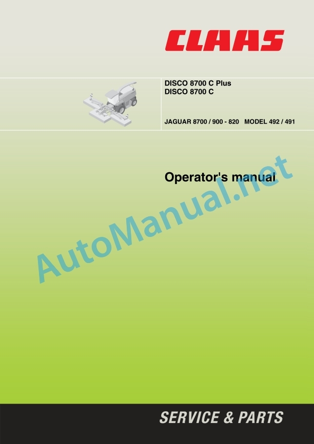
Claas Disco 8700 C C Plus (654) Mower Operator Manual EN
$50.00
- Model: Disco 8700 C C Plus (654) Mower
- Type Of Manual: Operator Manual
- Language: EN
- Format: PDF(s)
- Size: 64.9 MB
File List:
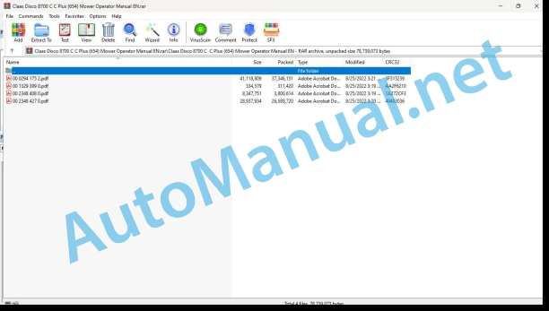
00 0294 175 2.pdf
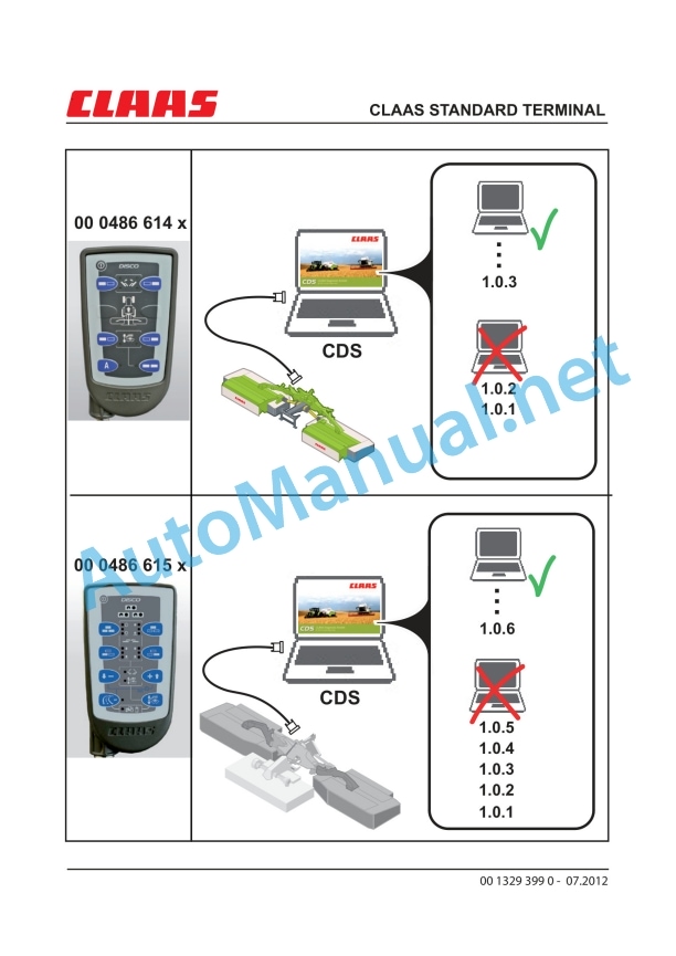
00 1329 399 0.pdf
00 2348 408 0.pdf
00 2348 427 0.pdf
00 0294 175 2.pdf:
1 Introduction
Introduction
Road traffic
Legal requirements for driving on public roads
General operating permit (ABE)
Driving on public roads
2 Contents
3 Preface
Of special importance
Identification plate
4 Safety Rules
Intended use
Identification of warning and dan ger signs
General safety and accident pre vention instructions
Attached machines
Attached devices
PTO Operation
Hydraulic system
Maintenance
Sound pressure level
Safety decals with pictorials
5 Specifications
6 Prior to Operation
Check and observe the following before putting into operation!
Adaptations to the forage har vester
Conversion steps
Additional weights
Lighting
Attachment to the tractor
Fitting the mounting frame
Hydraulic system
Universal drive shaft
Electrical system
Driving lights
Lowering speed
Adjusting the lowering speed of the mower unit suspension
Increasing the lifting speed
Safety devices
Suspension springs
Restricting the ground contour tracking (side mower units)
Checking the position of the upper link
Transport stop
Removing the machine
Removing the middle mower unit
Prior to transportation
Driving on public roads
Reinstating
Reinstating JAGUAR 900 / 890 / 870 / 850 / 830
Reinstating restrictors
Reinstating the central electrics
Reinstating JAGUAR 880 / 860 / 840 / 820
Reinstating the hydraulic control
Reinstating the central electrics
Reinstating the pressure accumulators
Reinstating the central lubrication
Miscellaneous
7 Operation
Operation of JAGUAR 8700 / 900 / 890 / 870 / 850 / 830
Multifunction lever
Control terminal
Working position
Adjusting mower unit relief
Setting the cutting height
Changing the swath width
Conditioner
Baffle plates
Changing the speed
Collision protection
Rotation monitoring
Fault display:
Fault display:
Recommendations for environmental protection
Transport position
Emergency functions
Operating the JAGUAR 880 / 860 / 840 / 820
Multifunction lever
Control terminal
Working position
Adjusting mower unit relief
Setting the cutting height
Changing the swath width
Conditioner
Baffle plates
Changing the speed
Collision protection
Rotation monitoring
Fault display:
Fault display:
Recommendations for environmental protection
Transport position
Emergency functions
Optional equipment
High cutting runners
Push-on runners
8 Maintenance
Important maintenance instructions
Hydraulic system
Energy accumulators
Lubrication
Safety devices
Tensioning the drive belts (main gearbox)
Tensioning the drive belt (Conditioner)
Drive diagram
Mounting frame
Middle mower unit
Side mower units
Mower head
Universal drive shaft
Clutches
Maintenance of the plate clutch
Mower blades
Mower blade box
Change mower blades.
Mower blade quick-change system
Mower blade holder (Mower-blade quick-change sys tem)
Bolted mower blades
Fastening mower blades (bolted mower blades)
Mower discs
Replacing cutting discs
Mower disc cap
Fitting pinion units
Spring adjustment
Ground contour following (middle mower unit)
Conditioner tines
Fitting/removing tines
Electrical system
Setting the rotation sensors
Hydraulic system
Hydraulic hoses
Hydraulic cylinder with vacuum valve
Pressure accumulators
Adjusting the safety pressure limiting valve
Safety devices
Fold-away guard frames
Sleeve protector
Lubrication openings
Screw connections
Connecting elements
End of season storage
Malfunctions
9 Lubrication chart
Safety Rules
Lubricants
Lubrication
00 2348 408 0.pdf:
CEMIS 100
Table of contents
1 Introduction
1.1 General information
1.1.1 Validity of the manual
1.1.2 Information about this Operator’s Manual
1.1.3 Symbols and notes
1.2 Intended use
1.2.1 Intended use
1.2.2 Reasonably foreseeable misuse
2 Safety
2.1 Safety rules
2.1.1 General safety and accident prevention regulations
2.1.2 Interaction between terminal and machine or tractor
2.1.3 Electrocution by electrical system
3 Product description
3.1 Overview and method of operation
3.1.1 Overview of CEMIS 100
3.1.2 Function principle of CEMIS 100
3.2 Identification plates and identification numbers
3.2.1 Spare parts and technical questions
3.2.2 Identification plate of CEMIS 100
4 Operating and display elements
4.1 CEMIS 100
4.1.1 User interface for LINER
4.1.2 User interface for ROLLANT
4.1.3 User interface for UNIWRAP
5 Technical specifications
5.1 CEMIS 100
5.1.1 Specification
6 Operation
6.1 CEMIS 100
6.1.1 Operating the CEMIS 100
6.1.2 Switching CEMIS 100 on
6.1.3 Switching CEMIS 100 off
7 Maintenance
7.1 CEMIS 100
7.1.1 Daily
8 Putting out of operation and disposal
8.1 General information
8.1.1 Removal from service and disposal
9 Technical terms and abbreviations
9.1 Terms and explanations
9.1.1 Technical words
9.1.2 Abbreviations
00 2348 427 0.pdf:
CEMIS 700
Table of contents
1 Introduction
1.1 General information
1.1.1 Validity of the manual
1.1.2 Information about this Operator’s Manual
1.1.3 Symbols and notes
1.2 Intended use
1.2.1 Intended use
1.2.2 Reasonably foreseeable misuse
2 Safety
2.1 Safety rules
2.1.1 General safety and accident prevention regulations
2.1.2 Interaction between terminal and machine or tractor
2.1.3 Electrocution by electrical system
3 Product description
3.1 Overview and method of operation
3.1.1 Overview of CEMIS 700
3.1.2 Function principle of CEMIS 700
3.2 Identification plates and identification numbers
3.2.1 Spare parts and technical questions
3.2.2 Identification plate of CEMIS 700
4 Information on the product
4.1 Software version
5 Operating and display elements
5.1 CEMIS 700
5.1.1 User interface
5.1.2 Terminal program
6 Technical specifications
6.1 CEMIS 700
6.1.1 Specification
7 Operation
7.1 CEMIS 700
7.1.1 Operating the CEMIS 700
7.1.2 Switching CEMIS 700 on
7.1.3 Switching CEMIS 700 off
7.2 Terminal settings
7.2.1 Making settings
Making settings with the rotary button
Making settings with the touch function
7.2.2 Setting the screen lighting
Daytime mode
Nighttime mode
Activating automatic key lighting
7.2.3 Setting the time and date
7.2.4 Displaying diagnosis information
On-board power supply voltage display
Display of CLAAS ISOBUS ECU address and name
7.2.5 Setting the language and display formats
Setting the language
Setting display formats
7.2.6 Setting the volume
7.2.7 Deleting an ISOBUS implement
8 Maintenance
8.1 Maintenance
8.1.1 Daily
9 Putting out of operation and disposal
9.1 General information
9.1.1 Removal from service and disposal
10 Technical terms and abbreviations
10.1 Terms and explanations
10.1.1 Technical words
10.1.2 Abbreviations
John Deere Parts Catalog PDF
John Deere Harvesters 8500 and 8700 Parts Catalog CPCQ24910 Spanish
John Deere Parts Catalog PDF
John Deere Tractors 7500 Parts Catalog CPCQ26568 30 Jan 02 Portuguese
John Deere Repair Technical Manual PDF
John Deere Repair Technical Manual PDF
John Deere Diesel Engines PowerTech 4.5L and 6.8L – Motor Base Technical Manual 07MAY08 Portuguese
John Deere Repair Technical Manual PDF
John Deere Repair Technical Manual PDF
John Deere Repair Technical Manual PDF
John Deere Parts Catalog PDF
John Deere Tractors 6300, 6500, and 6600 Parts Catalog CQ26564 (29SET05) Portuguese
John Deere Repair Technical Manual PDF
John Deere Repair Technical Manual PDF

