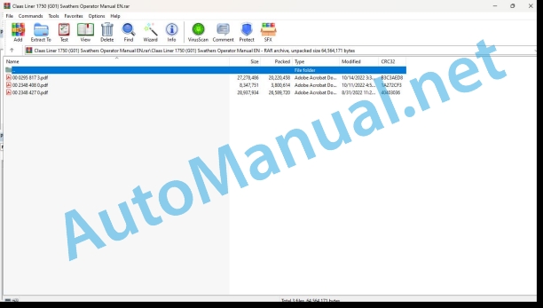
Claas Liner 1750 (G01) Swathers Operator Manual EN
$50.00
- Model: Liner 1750 (G01) Swathers
- Type Of Manual: Operator Manual
- Language: EN
- Format: PDF(s)
- Size: 48.3 MB
File List:
00 0295 817 3.pdf
00 2348 408 0.pdf
00 2348 427 0.pdf
00 0295 817 3.pdf:
LINER 1750
Table of contents
1 To this Operator’s Manual
1.1 Notes on the manual
1.1.1 General instructions
1.1.2 Validity of manual
1.1.3 Using this manual
Directional indicators
1.1.4 Technical specifications
1.1.5 Symbols and notes
2 Safety
2.1 Safety rules
2.1.1 Particularly important
2.1.2 Qualification of drivers and maintenance personnel
2.1.3 Intended use
2.1.4 Reasonably foreseeable misuse
2.1.5 Safety and accident prevention regulations
2.1.6 First aid measures
2.1.7 Danger of injury from hydraulic liquid
2.2 Safety decals on the machine
2.2.1 Safety decals
2.2.2 Position of safety decals
3 Machine description
3.1 Overview and method of operation
3.1.1 Overview of LINER 1750
3.1.2 Function of machine
3.2 Optional machine equipment
3.2.1 CLAAS STANDARD TERMINAL*
3.2.2 CLAAS COMMUNICATOR
3.2.3 ISOBUS connecting cable
3.2.4 Hydraulic rotor height adjustment
3.2.5 Rear tandem axles
3.2.6 Spare wheel, 16×6.5-8
3.2.7 Wheel weights
3.2.8 Hydraulic connectors, 3-part
3.2.9 Slip-on yoke, 8-piece
3.2.10 Lighting adapter for USA
3.2.11 SMV triangle
3.3 Identification plates and vehicle identification number
3.3.1 Spare parts and technical questions
3.3.2 Position of identification plate
3.3.3 Position of identification number
3.3.4 Explanation of machine identification plate
3.4 Information on the machine
3.4.1 Decal
4 Operating and control elements
4.1 Control terminal
4.1.1 CLAAS Standard Terminal*
Overview of keys and LEDs
4.1.2 CLAAS COMMUNICATOR*
Terminal overview
4.2 ISOBUS control unit
4.2.1 Monitor
4.2.2 Menu bar
Fieldwork menu
Information menu
4.2.3 Data field
4.3 Rotor
4.3.1 Crank
4.3.2 Raking height scale
4.3.3 Rope
4.4 Hydraulic hose line
4.4.1 Shut-off tap
4.5 Jack stand
4.5.1 Knob
5 Technical specifications
5.1 LINER 1750
5.1.1 Dimensions
5.1.2 Weights
5.1.3 Requirements on the tractor
5.1.4 Design
5.1.5 Tyre inflation pressure
5.1.6 Noise level
5.1.7 Lubricants
6 Machine preparation
6.1 Adapting the machine
6.1.1 Universal drive shaft – Checking the length
6.1.2 Universal drive shaft – Adapting the length
6.1.3 Fitting the universal drive shaft to the machine
6.1.4 Fitting the wheel weights*
6.1.5 Installing the CLAAS Standard Terminal*
6.1.6 Installing the CLAAS COMMUNICATOR*
6.2 Hitching the machine
6.2.1 Connecting the hitching bracket
6.2.2 Adjusting the hitching bracket
6.2.3 Installing the universal drive shaft
6.2.4 Connecting the hydraulic hose
6.2.5 Fitting the pull rope
6.2.6 Connecting the lighting cable
6.2.7 Stowing the wheel chocks
6.3 Unhitching the machine
6.3.1 Positioning the wheel chock at the wheel
6.3.2 Disconnecting the lighting cable
6.3.3 Storing the control terminal
6.3.4 Disconnecting the pull rope
6.3.5 Disconnecting the hydraulic hoses
6.3.6 Removing the universal drive shaft
6.3.7 Unhitching the hitch bracket
6.4 Prepare road travel
6.4.1 General safety precautions
6.4.2 Folding in the safety frame
6.4.3 Removing the tine arms
6.4.4 Pushing the windrowing rubber to the inside
6.4.5 Arrest windrowing rubber in the transport position
6.4.6 Folds the machine to transport position
6.4.7 Closing the shut-off tap
6.4.8 Fitting the safety bars
6.5 Preparing the working position
6.5.1 Removing protection strips
6.5.2 Opening the shut-off tap
6.5.3 Folding the machine to the working position
6.5.4 Fitting the tine arms
6.5.5 Folding the windrowing rubber to working position
6.5.6 Folding out the guard frames
6.6 Loading the machine
6.6.1 Lifting the machine
7 Operation
7.1 General safety precautions
7.1.1 Prior to operation
7.2 Driving on the road
7.2.1 Driving on public roads
7.3 Fieldwork settings
7.3.1 General instructions
7.3.2 Adjusting the swathing rotors
7.3.3 Raking height adjustment
7.3.4 Adjusting the windrowing rubber
7.3.5 Setting the headland position
7.3.6 Adjusting the hydraulic sequential control
7.3.7 Adjusting the steering angle stop
7.4 Fieldwork
7.4.1 Fieldwork
7.4.2 Observing the steering angle
7.4.3 Swathing
Adjusting the rotor overlap
7.4.4 Swathing straw
Additional windrowing rubber*
7.4.5 Engaging the PTO shaft
Optimum PTO speed
7.4.6 Lifting the swathing rotors to the headland position
Hydraulic sequential control
7.5 CLAAS STANDARD TERMINAL
7.5.1 General warnings
7.6 Switching the CLAAS STANDARD TERMINAL on/off
7.6.1 Switching on the terminal
7.6.2 Switching off the terminal
7.6.3 Terminal – automatic shutdown
7.7 CLAAS STANDARD TERMINAL working position
7.7.1 Lowering all rotors
7.7.2 Lift all rotors (automatic headland mode)
7.8 CLAAS STANDARD TERMINAL working width
7.8.1 Increasing / reducing the working width
7.9 CLAAS STANDARD TERMINAL raking height
7.9.1 Increasing/reducing the raking height
7.10 CLAAS STANDARD TERMINAL transport position
7.10.1 Folding to transport position
7.11 ISOBUS control unit
7.11.1 Description
7.11.2 Notes on this chapter
7.11.3 Explanations regarding the ISOBUS terms
7.12 ISOBUS transport
7.12.1 Transport position
7.13 ISOBUS working position
7.13.1 Working position
7.14 ISOBUS fieldwork
7.14.1 Working width preselection
7.14.2 Headland position pre-selection
7.14.3 Raking height (option)
7.15 CLAAS COMMUNICATOR
7.15.1 Notes on this chapter
7.15.2 Recommendations to achieve best possible use
7.16 Switching the CLAAS COMMUNICATOR on/off
7.16.1 Switching the CLAAS COMMUNICATOR on
7.16.2 Switching the CLAAS COMMUNICATOR off
7.17 Operating the CLAAS COMMUNICATOR
7.17.1 Select menu“ / cancel key (ESC)
7..Function keys
7.17.3 Select wheel – data selection and data input
7.17.4 Navigation in the data field
7.17.5 Programmable keys
7.17.6 Software maintenance
7.18 CLAAS COMMUNICATOR service program
7.18.1 Scope of functions
7.18.2 Calling up the service program
7.19 Overview of CLAAS COMMUNICATOR service program
7.19.1 Monitor
7.19.2 Title bar
7.19.3 Menu bar
7.19.4 Data field
7.19.5 Softkey
7.20 CLAAS COMMUNICATOR menu descriptions
7.20.1 Changing the menu
7.20.2 Information menu
7.20.3 Brightness / contrast menu
7.20.4 Time and date menu
7.20.5 Memory administration menu
7.20.6 Diagnosis sub-menu
7.20.7 Country settings menu
7.20.8 Auxiliary function (AUX) menu
8 Faults and remedies
8.1 Causes and remedies
8.1.1 Observe for troubleshooting
8.1.2 Hydraulic system
8.1.3 Sensing wheels
8.2 Emergency operation
8.2.1 Information about emergency operation
8.2.2 Overview of hydraulic valves
8.2.3 Work steps prior to emergency operation
8.2.4 Actuating the hydraulic valves manually
9 Maintenance
9.1 Maintenance Information
9.1.1 General maintenance warnings
9.1.2 Electrical system
9.1.3 Protective guards
9.1.4 Spare parts
9.1.5 Unbalance
9.1.6 Compressed air and water
9.1.7 Wheels / tyres
9.1.8 Burn prevention
9.1.9 Oils
9.1.10 Fire prevention and explosion prevention
9.1.11 Lines, tubes and hoses
9.2 Overview maintenance intervals
9.2.1 Dealing with maintenance intervals
9.2.2 Before the harvest
9.2.3 After the first 10 operating hours
9.2.4 After the first 50 operating hours
9.2.5 Every 8 operating hours or daily
9.2.6 Every 20 operating hours
9.2.7 Every 50 operating hours
9.2.8 Every 100 operating hours
9.2.9 Every 250 operating hours
9.2.10 Every 500 operating hours or annually
9.2.11 As needed
9.2.12 After the harvest
9.3 Maintenance operations in general
9.3.1 Clean the machine
9.3.2 Preserve the machine
9.3.3 Preventing frost damage
9.3.4 Fastening material
9.4 Maintenance operations gearbox
9.4.1 Check gearbox tightness
9.4.2 Checking the main gearbox oil level
9.4.3 Changing the main gearbox oil
9.4.4 Retightening the main gearbox bolts
9.4.5 Checking the angle drive oil level
9.4.6 Changing the angle drive oil
9.4.7 Retightening the angle drive bolts
9.4.8 Checking the swathing gearbox oil level
9.4.9 Changing the swathing gearbox oil
9.4.10 Retightening the swathing gearbox bolts
9.5 Maintenance operations clutch
9.5.1 Adjusting the locking element clutch
9.6 Maintenance operations drive shaft
9.6.1 Maintaining drive shafts
9.6.2 Retightening the universal drive shaft nuts
9.7 Maintanance operations chassis
9.7.1 Check the tyre pressure
9.7.2 Changing a land wheel
9.7.3 Changing a sensing wheel
Rear tandem axle*
9.7.4 Check / adjust track
Adjusting the steering rod
9.7.5 Checking / adjusting the toe-in
9.8 Maintenance operations hydraulic
9.8.1 Hydraulic system maintenance
9.8.2 Maintaining hydraulic hoses
9.9 Frame maintenance work
9.9.1 Checking the hitching bracket
9.9.2 Checking the frame mounting
9.10 Rotor maintenance
9.10.1 Checking the swathing gearbox fastening
9.10.2 Checking the swathing rotor suspension
9.10.3 Adjusting releasing springs
9.10.4 Check bracket for tine bars
9.10.5 Check spring tines
9.11 Lubrication chart
9.11.1 Grease points to be greased every 20 h
9.11.2 Grease points to be greased every 50 h
9.11.3 Grease points to be greased every 100 h
9.11.4 Grease points to be greased every 250 h
10 Placing out of operation and disposal
10.1 General information
10.1.1 Putting out of operation and disposal
11 EC declaration of conformity
11.1 EC Declaration of Conformity
12 Technical terms and abbreviations
12.1 Terms and explanations
12.1.1 Technical terms
12.1.2 Abbreviations
00 2348 408 0.pdf:
CEMIS 100
Table of contents
1 Introduction
1.1 General information
1.1.1 Validity of the manual
1.1.2 Information about this Operator’s Manual
1.1.3 Symbols and notes
1.2 Intended use
1.2.1 Intended use
1.2.2 Reasonably foreseeable misuse
2 Safety
2.1 Safety rules
2.1.1 General safety and accident prevention regulations
2.1.2 Interaction between terminal and machine or tractor
2.1.3 Electrocution by electrical system
3 Product description
3.1 Overview and method of operation
3.1.1 Overview of CEMIS 100
3.1.2 Function principle of CEMIS 100
3.2 Identification plates and identification numbers
3.2.1 Spare parts and technical questions
3.2.2 Identification plate of CEMIS 100
4 Operating and display elements
4.1 CEMIS 100
4.1.1 User interface for LINER
4.1.2 User interface for ROLLANT
4.1.3 User interface for UNIWRAP
5 Technical specifications
5.1 CEMIS 100
5.1.1 Specification
6 Operation
6.1 CEMIS 100
6.1.1 Operating the CEMIS 100
6.1.2 Switching CEMIS 100 on
6.1.3 Switching CEMIS 100 off
7 Maintenance
7.1 CEMIS 100
7.1.1 Daily
8 Putting out of operation and disposal
8.1 General information
8.1.1 Removal from service and disposal
9 Technical terms and abbreviations
9.1 Terms and explanations
9.1.1 Technical words
9.1.2 Abbreviations
00 2348 427 0.pdf:
CEMIS 700
Table of contents
1 Introduction
1.1 General information
1.1.1 Validity of the manual
1.1.2 Information about this Operator’s Manual
1.1.3 Symbols and notes
1.2 Intended use
1.2.1 Intended use
1.2.2 Reasonably foreseeable misuse
2 Safety
2.1 Safety rules
2.1.1 General safety and accident prevention regulations
2.1.2 Interaction between terminal and machine or tractor
2.1.3 Electrocution by electrical system
3 Product description
3.1 Overview and method of operation
3.1.1 Overview of CEMIS 700
3.1.2 Function principle of CEMIS 700
3.2 Identification plates and identification numbers
3.2.1 Spare parts and technical questions
3.2.2 Identification plate of CEMIS 700
4 Information on the product
4.1 Software version
5 Operating and display elements
5.1 CEMIS 700
5.1.1 User interface
5.1.2 Terminal program
6 Technical specifications
6.1 CEMIS 700
6.1.1 Specification
7 Operation
7.1 CEMIS 700
7.1.1 Operating the CEMIS 700
7.1.2 Switching CEMIS 700 on
7.1.3 Switching CEMIS 700 off
7.2 Terminal settings
7.2.1 Making settings
Making settings with the rotary button
Making settings with the touch function
7.2.2 Setting the screen lighting
Daytime mode
Nighttime mode
Activating automatic key lighting
7.2.3 Setting the time and date
7.2.4 Displaying diagnosis information
On-board power supply voltage display
Display of CLAAS ISOBUS ECU address and name
7.2.5 Setting the language and display formats
Setting the language
Setting display formats
7.2.6 Setting the volume
7.2.7 Deleting an ISOBUS implement
8 Maintenance
8.1 Maintenance
8.1.1 Daily
9 Putting out of operation and disposal
9.1 General information
9.1.1 Removal from service and disposal
10 Technical terms and abbreviations
10.1 Terms and explanations
10.1.1 Technical words
10.1.2 Abbreviations
John Deere Repair Technical Manual PDF
John Deere 18-Speed PST Repair Manual Component Technical Manual CTM168 10DEC07
John Deere Repair Technical Manual PDF
John Deere Repair Technical Manual PDF
John Deere Application List Component Technical Manual CTM106819 24AUG20
John Deere Repair Technical Manual PDF
John Deere Transmission Control Unit Component Technical Manual CTM157 15JUL05
John Deere Repair Technical Manual PDF
John Deere Repair Technical Manual PDF
John Deere Parts Catalog PDF
John Deere Tractors 6300, 6500, and 6600 Parts Catalog CQ26564 (29SET05) Portuguese
John Deere Repair Technical Manual PDF
John Deere 16, 18, 20 and 24HP Onan Engines Component Technical Manual CTM2 (19APR90)


