Claas Liner 3000 (605) Swathers Operator Manual EN
$50.00
- Model: Liner 3000 (605) Swathers
- Type Of Manual: Operator Manual
- Language: EN
- Format: PDF(s)
- Size: 38.0 MB
File List:
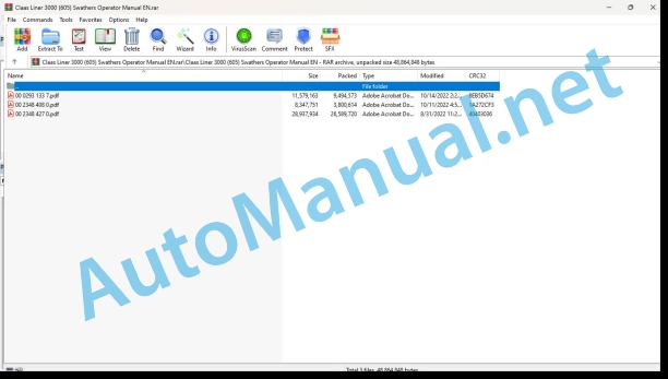
00 0293 133 7.pdf
00 2348 408 0.pdf
00 2348 427 0.pdf
00 0293 133 7.pdf:
1 Machine description
2 Introduction
2.1 General information
2.2 Identifying the machine
2.2.1 Validity
2.2.2 Identification plate
3 Contents
4 Safety notes
4.1 Of special importance
4.1.1 Prop stand
4.2 Safety rules
4.2.1 Identification of warning and danger signs
4.2.2 Designated use
4.2.3 General safety and accident prevention regulations
4.2.4 Mounted machines
4.2.5 Trailed machines
4.2.6 PTO operation
4.2.7 Hydraulic system
4.2.8 Tyres
4.2.9 Maintenance
4.2.10 Noise level
4.3 Safety decals with pictorals
5 Specifications
6 Work to be done before first operation
6.1 Adapting the tractor
6.1.1 Electrical system
Power demand (supplementary equipment)
6.1.2 Holder for Terminal/CLAAS Communicator/Operating terminal
6.1.3 Ballast weights
6.2 Hitching/adapting the swather
6.2.1 Adapting the hitching points
6.2.2 Adapting the universal drive shaft
6.2.3 Adapting the hydraulics
Constant flow pump
Constant pressure pump
Load sensing of hydraulic coupling (swather with ISOBUS Terminal)
7 Check every time before operation
8 Hitching/unhitching the machine
8.1 Hitching the machine
Proceed as follows to hitch the machine:
8.1.1 Attaching to the bottom links
8.1.2 Mounting the universal drive shaft
8.1.3 Prop stand
8.1.4 Connecting the hydraulics
8.1.5 Opening the shut-off valve for the rear rotors (only applies up to Serial No. 60501857)
8.1.6 Connecting the electrical system
8.1.7 Connecting the pneumatic brake system
8.1.8 Connecting the hydraulic brake system
8.1.9 Parking brake
8.1.10 Wheel chocks
8.1.11 Connecting ISOBUS Terminal
8.1.12 Installing the operating terminal
8.2 Unhitching and parking the machine
Closing the shut-off valves for rear rotors (up to Serial No. 605 0 1857)
Mechanical lock for the rear rotors (from Serial No. 605 0 1858)
8.2.1 Parking the machine at sub-zero temperatures
9 Driving and road transport
9.1 Transport on public roads
9.1.1 Driving licence
9.1.2 Identification plates
9.1.3 Transport on public roads
9.2 Transport position with ISOBUS Terminal
9.3 Transport position with operating terminal
9.4 Before transport
9.4.1 Removing the tine arms
9.4.2 Swing lighting bracket upwards
9.5 Before lowering into the working position
Removing the tine guards
9.6 Working position with ISOBUS Terminal
9.7 Working position with operating terminal
9.8 Before starting field operation
9.8.1 Mounting the tine arms
9.9 Unloading/loading the machine
10 Operation – CLAAS Communicator
10.1 CLAAS Communicator
10.1.1 Overview of hardware keys
10.1.2 Overview of display
10.1.3 Soft Keys
10.1.4 Soft key “STOP”
10.1.5 Switching on/off the CLAAS Communicator
10.1.6 “Menu Selection” key
10.1.7 “Terminal” knob
10.2 Serv ce start menu
10.2.2 Brightness and contrast
Changing the screen contrast
Changing the screen brightness
10.2.3 Setting date and time
10.2.4 Country settings:
10.2.5 AUX
10.2.6 Software management
Memory management
Deleting memory space
11 Operation – ISOBUS Terminal
11.1 Display
11.1.1 Overview of display
11.1.2 Title bar
11.1.3 Menu bar
11.1.4 Soft Key icons
11.1.5 Status bar
11.1.6 Data field
11.1.7 Software Version
11.1.8 Service menu/memory administration
11.2 Programming ISOBUS Terminal
11.2.1 Initial settings
11.2.2 Query of saved “Headland values”
11.2.3 Adjusting the working width
11.2.4 Adjusting the headland settings
Clearance height for headland
Delay when raising rotors
Delay when lowering rotors
11.3 Manual control
11.3.1 Of special importance
11.3.2 Activating manual control
Calling manual mode from the “Working Position” screen
Calling man from the “port” screen
11.3.3 Running gear
11.3.4 Raising/lowering the rotors
11.3.5 Setting the height of the rotor (Rake height, additional equipment)
11.3.6 Reducing/increasing the working width
11.3.7 Switching off the manual control
11.4 Basic setting (initialisation)
11.4.1 Starting the initialization process
11.4.2 Basic headland settings
11.5 Manual operation of hydraulic system
12 Operation – Control terminal
12.1 Control terminal
12.1.1 Survey of keys
Switching the control terminal on and off
12.1.2 Indicator light
12.2 Adjustments using the control terminal
12.2.1 Adjusting the headland position
Raising the rotors
Lowering the rotors
12.2.2 Basic headland setting
12.2.3 Clearance height at headland
12.3 Manual control
12.3.1 Of special importance
12.3.2 Activating manual control
12.3.3 Running gear
12.3.4 Raising/lowering the rotors
12.3.5 Increasing/decreasing the working width (rotor ove)
12.3.6 Switching f the manual control
12.4 Basic setting (initialisation)
12.4.1 Start initialization
12.4.2 Initialization completed
12.5 Emergency operation
12.5.1 Functional test of angle encoders
12.6 Manual operation of hydraulic system
13 Field operation
13.1 Using the swather
Minimum working width
13.1.1 Using the machine with ISOBUS Terminal
Adjusting the working width (rotor overlap)
Raising/lowering the rotors to the headland position
Working with individual rotors
Soft key “Selecting rotor controller”
Overview of “single actuation” soft keys
13.1.2 Using the machine with the control terminal
Adjusting the working width (rotor overlap)
Lifting/lowering the rotors at the headland
Working with the rear rotors
13.1.3 Changing the swath width
13.1.4 Height adjustment of rotors (rake height)
Mechanical height adjustment
Hydraulic rotor height adjustment (Additional equipment – only with ISOinal)
13.2 Accessory eq 13.2.1 Individual raising of the front rotors (only for swathers with control terminal)
13.2.2 Slip yoke kit (M03/0010)
13.2.3 Hydraulic couplings for tractors (R03/0020)
13.2.4 Adapter for USA road lighting (USA, R03/0500)
14 Trouble shooting
14.1 General faults
14.2 Error messages in the display (swather with ISOBUS Terminal)
15 Maintenance
15.1 Important notes on maintenance
15.1.1 Spare parts
15.1.2 Screws and bolts
15.1.3 Tyres
15.1.4 Hydraulic system
15.1.5 Lubrication
15.1.6 Protective devices
15.2 Maintenance schedule
15.3 Lubricants chart
15.4 Drives
15.4.1 Rotor drive
Leakage check on rotor drive
Checking lubricant level in rotor drive
Sealing the rotor drive housing (clamp bearings without moulded-on seals)
Sealing the rotor drive housing (clamp bearings with moulded-on seals)
15.4.2 Angle drives
15.4.3 Universal drive shaft
General information on universal drive shafts
15.4.4 Assembling/dismantling the universal drive shaft protection
15.5 Brakes
15.5.1 Pneumatic brake system
Draining the compressed air tank
Air filters for pneumatic hoses
Cleaning the filter elements
Air filter components
Checking/adjusting the brake cylinder stroke
15.6 Adjustment work
15.6.1 Flotation springs
15.6.2 Rotor flotation
15.6.3 Adjusting the reed switch (from Serial No.: 605 0 1113 onwards)
15.6.4 Adjusting the overspeed monitor
15.6.5 Angle encoders
15.6.6 Angle sensor (LINER 3000 with ISOBUS Terminal from serial No.: 605 0 2103)
15.6.7 Checking/adjusting the track
Checking toe-in
Adjusting toe-in
15.7 Rotor running gear
15.8 Tyres
15.8.1 Tyre pressure
15.8.2 Wheel change
15.9 Hydraulics
15.9.1 Hydraulic hoses
15.9.2 Replacing the pressure filter
15.10 Fixing elements
15.10.1 Threaded fasteners
15.10.2 Fasteners
Quick fit connector bracket securing device
Wear discs bracket securing device
Spring bracket securing device
15.11 Recommendations for winter storage
16 Lubricating chart
Lubricants
Lubrication intervals
00 2348 408 0.pdf:
CEMIS 100
Table of contents
1 Introduction
1.1 General information
1.1.1 Validity of the manual
1.1.2 Information about this Operator’s Manual
1.1.3 Symbols and notes
1.2 Intended use
1.2.1 Intended use
1.2.2 Reasonably foreseeable misuse
2 Safety
2.1 Safety rules
2.1.1 General safety and accident prevention regulations
2.1.2 Interaction between terminal and machine or tractor
2.1.3 Electrocution by electrical system
3 Product description
3.1 Overview and method of operation
3.1.1 Overview of CEMIS 100
3.1.2 Function principle of CEMIS 100
3.2 Identification plates and identification numbers
3.2.1 Spare parts and technical questions
3.2.2 Identification plate of CEMIS 100
4 Operating and display elements
4.1 CEMIS 100
4.1.1 User interface for LINER
4.1.2 User interface for ROLLANT
4.1.3 User interface for UNIWRAP
5 Technical specifications
5.1 CEMIS 100
5.1.1 Specification
6 Operation
6.1 CEMIS 100
6.1.1 Operating the CEMIS 100
6.1.2 Switching CEMIS 100 on
6.1.3 Switching CEMIS 100 off
7 Maintenance
7.1 CEMIS 100
7.1.1 Daily
8 Putting out of operation and disposal
8.1 General information
8.1.1 Removal from service and disposal
9 Technical terms and abbreviations
9.1 Terms and explanations
9.1.1 Technical words
9.1.2 Abbreviations
00 2348 427 0.pdf:
CEMIS 700
Table of contents
1 Introduction
1.1 General information
1.1.1 Validity of the manual
1.1.2 Information about this Operator’s Manual
1.1.3 Symbols and notes
1.2 Intended use
1.2.1 Intended use
1.2.2 Reasonably foreseeable misuse
2 Safety
2.1 Safety rules
2.1.1 General safety and accident prevention regulations
2.1.2 Interaction between terminal and machine or tractor
2.1.3 Electrocution by electrical system
3 Product description
3.1 Overview and method of operation
3.1.1 Overview of CEMIS 700
3.1.2 Function principle of CEMIS 700
3.2 Identification plates and identification numbers
3.2.1 Spare parts and technical questions
3.2.2 Identification plate of CEMIS 700
4 Information on the product
4.1 Software version
5 Operating and display elements
5.1 CEMIS 700
5.1.1 User interface
5.1.2 Terminal program
6 Technical specifications
6.1 CEMIS 700
6.1.1 Specification
7 Operation
7.1 CEMIS 700
7.1.1 Operating the CEMIS 700
7.1.2 Switching CEMIS 700 on
7.1.3 Switching CEMIS 700 off
7.2 Terminal settings
7.2.1 Making settings
Making settings with the rotary button
Making settings with the touch function
7.2.2 Setting the screen lighting
Daytime mode
Nighttime mode
Activating automatic key lighting
7.2.3 Setting the time and date
7.2.4 Displaying diagnosis information
On-board power supply voltage display
Display of CLAAS ISOBUS ECU address and name
7.2.5 Setting the language and display formats
Setting the language
Setting display formats
7.2.6 Setting the volume
7.2.7 Deleting an ISOBUS implement
8 Maintenance
8.1 Maintenance
8.1.1 Daily
9 Putting out of operation and disposal
9.1 General information
9.1.1 Removal from service and disposal
10 Technical terms and abbreviations
10.1 Terms and explanations
10.1.1 Technical words
10.1.2 Abbreviations
John Deere Repair Technical Manual PDF
John Deere Repair Technical Manual PDF
John Deere Parts Catalog PDF
John Deere Tractors 7500 Parts Catalog CPCQ26568 30 Jan 02 Portuguese
John Deere Repair Technical Manual PDF
John Deere Repair Technical Manual PDF
John Deere Diesel Engines PowerTech 4.5L and 6.8L – Motor Base Technical Manual 07MAY08 Portuguese
John Deere Repair Technical Manual PDF
John Deere Repair Technical Manual PDF
John Deere Repair Technical Manual PDF
John Deere Repair Technical Manual PDF
John Deere Transmission Control Unit Component Technical Manual CTM157 15JUL05


