Claas Scorpion 7030 (K12) Telehandlers Operator Manual EN
$50.00
- Model: Scorpion 7030 (K12) Telehandlers
- Type Of Manual: Operator Manual
- Language: EN
- Format: PDF(s)
- Size: 57.7 MB
File List:
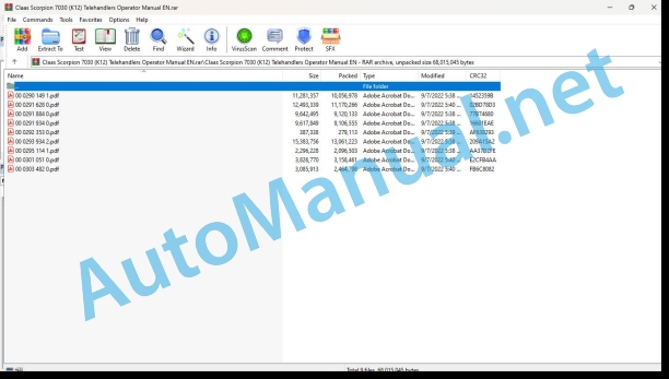
00 0290 149 1.pdf
00 0291 628 0.pdf
00 0291 884 0.pdf
00 0291 934 0.pdf
00 0292 353 0.pdf
00 0293 934 2.pdf
00 0295 114 1.pdf
00 0301 051 0.pdf
00 0303 482 0.pdf
00 0290 149 1.pdf:
Operator’s Manual
Contents
1 Introduction
1.1 General information on the Operator’s Manual
1.2 General information on machine safety
1.3 Machine overview
1.4 Model designation – trade names
1.5 Brief description of telehandler
1.6 Fields of application and using a telehandler with an attachment
1.7 Telehandler warranty
1.8 Regulations regarding telehandler operation
1.9 Type labels and component numbers
1.10 Description of labels
2 Safety instructions
2.1 Identification of warnings and dangers
2.2 Designated use and exemption from liability
2.3 General conduct and safety instructions
2.4 Safety instructions regarding operation
2.5 Safety instructions for maintenance
2.6 Maintenance work on protective ROPS and FOPS structures
2.7 Warning of special hazards
3 Operation
3.1 General information regarding the description of the control elements
3.2 Inside of cab: overview
3.3 Control elements on the control lever and switch consoles: overview
3.4 Telltales and warning lights: description
3.5 Putting the machine into service for the first time
3.7 Engine cover
3.8 Putting the diesel engine into service
3.9 Battery master switch
3.10 Error code displays (103 kW diesel engine)
3.11 Key-based drive interlock (option)
3.12 Drive interlock with code input (option)
3.13 Oil and fuel preheater (option)
3.14 Jump-starting the engine (external battery)
3.15 Before moving off
3.16 Steering system
3.17 Accelerator pedal
3.18 Manual throttle (option)
3.19 Brake/inching pedal
3.20 Parking brake
3.21 Moving off the telehandler
3.22 Stopping/parking the machine
3.23 Load stabiliser
3.24 Differential lock
3.25 Backup warning system (option)
3.26 Electric mirror adjustment (option)
3.27 Machine lights
3.28 Signalling system
3.29 Cab heating and ventilation
3.30 Air conditioning (option)
3.31 Washer system
3.32 Seat
3.33 Seat belt (lap belt)
3.34 Fire extinguisher (option)
3.35 Reversing fan (option)
3.36 Towing the machine
3.37 Loading and transporting the telehandler on a transport vehicle
3.38 Crane handling the machine
3.39 Telescopic boom control lever: overview
3.40 Operating and securing the 3rd control circuit
3.41 Safe load indicator for telescopic boom
3.42 Disabling/enabling the overload cutoff (option)
3.43 Operating the telescopic boom
3.44 Emergency lowering of telescopic boom in case of diesel engine breakdown
3.45 Equipping the machine with a standard bucket
3.46 Working with the standard bucket
3.47 Fitting a multipurpose bucket
3.48 Working with the multipurpose bucket
3.49 Fitting pallet forks
3.50 Working with the pallet forks
3.51 “Hose burst valve” safety feature
3.52 Working with a crane jib (option)
3.53 Continuous operation of 3rd control circuit (option)
3.54 Tilt ram lock (option)
3.55 Electric changeover valve for operation of 3rd control circuit as additional front control circuit (option)
3.56 Front/rear hydraulic additional control circuit (option)
3.57 Automatic bucket repositioning (option)
3.58 Tipping trailer connection (option)
3.59 Operation of the Autohitch trailer coupling (option)
3.60 Automatic trailer coupling (option)
3.61 Compressed-air brake system (option)
3.62 Hydraulic trailer brake (option)
3.63 Fitting attachments other than Kramer onto the quickhitch (option)
4 Troubleshooting
4.1 Diesel engine malfunctions
4.2 Malfunctions in the air conditioning system (option)
5 Maintenance
5.1 Important information on maintenance work
5.2 Safety prop for telescopic boom
5.3 Fuel system
5.4 Engine lcn system
5.5 Engine and hydraulics cooling system
5.6 Air filter
5.7 V-belts
5.8 Hydraulic system
5.9 Checking hydraulic pressure lines
5.10 Lubrication work
5.11 Lubricating with the central lubrication system (option)
5.12 Maintenance of the brake system
5.13 Maintenance: compressed-air brake system (option)
5.14 Tyres
5.15 Heating and ventilation system maintenance
5.16 Air conditioning (option): maintenance
5.17 Maintenance of the electrical system
5.18 Maintenance of the automatic trailer coupling (option)
5.19 General maintenance work
5.20 Maintenance of attachments and of the work equipment
5.21 Maintenance: diesel particulate filter (option)
5.22 Maintenance work “Aggressive Media” (option)
5.23 Maintenance plan (overview)
5.24 Fluids and lubricants
5.25 Maintenance label
6 Specifications
6.1 Model and trade names: overview
6.2 Frame
6.3 Engine
6.4 Oil/water cooling fan
6.5 Power train
6 Axl 6.7 Service and parking brake
6.8 Steering
6.9 Work hydraulics
6.10 Electrical system
6.11 Tyres for models 400-01/401-03/402-03/403-03
6.12 Weights
6.13 Noise levels
6.14 Vibrations, oscillation and acceleration value
6.15 Coolant compound table
6.16 Tightening torques
6.17 Trailer couplings: trailer weight/drawbar load
6.18 Payload: model 400-01 load diagram
6.19 Payload: load diagram without additional counterweight, model 401-03
6.20 Payload: load diagram with additional counterweight (2 x 150 kg) model 401-03
6.21 Payload: load diagram without additional counterweight, model 402-03
6.22 Payload: load diagram with additional counterweight (2 x 150 kg), model 402-03
6.23 Payload: load diagram model 403-03
6.24 Dimensions with bucket
6.25 Dimensions with pallet forks
00 0291 628 0.pdf:
Operator’s Manual
Contents
EC declaration of conformity (model 401-03)
EC declaration of conformity (model 402-03)
EC declaration of conformity (model 403-03)
1 Introduction
1.1 Operator’s Manual
1.2 Machine outside view
1.3 Brief description of telehandler
1.4 Telehandler warranty
1.5 Fields of application and using a telehandler with an attachment
1.6 Legal regulations regarding telehandler operation
1.7 Type labels and component numbers
1.8 Description of labels
2 Safety instructions
2.1 Identification of warnings and dangers
2.2 Designated use and exemption from liability
2.3 General conduct and safety instructions
2.4 Safety instructions regarding operation
2.5 Safety instructions for maintenance
2.6 Maintenance work on protective ROPS and FOPS structures
2.7 Warning of special hazards
3 Operation
3.1 Information regarding the description of the control elements
3.2 Inside of cab (overview)
3.3 Control elements on the control lever and switch consoles: overview
3.4 Indicator lights and warning lights: description
3.5 Before putting the machine into operation
3.7 Seat
3.8 Seat belt (lap belt)
3.9 Engine cover
3.10 Air-suspension seat (option)
3.11 Fire extinguisher (option)
3.12 Key-based drive interlock (option)
3.13 Drive interlock with code input (option)
3.14 Battery master switch
3.15 Oil and fuel preheater (option)
3.16 Putting the diesel engine into operation
3.17 Jump-starting the engine (external battery)
3.18 Error code displays (103 kW diesel engine)
3.19 Preparing for driving on public roads
3.20 Moving off the telehandler
3.21 Stopping/parking the machine
3.22 Steering system
3.23 Accelerator pedal
3.24 Manual throttle (option)
3.25 Brake/inching pedal
3.26 Parking brake
3.27 Telescopic boom load stabiliser
3.28 Differential lock
3.29 Backup warning system (option)
3.30 Electric mirror adjustment (option)
3.31 Reversing fan (option)
3.32 Machine lights
3.33 Signalling system
3.34 Cab heating and ventilation
3.35 Air conditioning (option)
3.36 Washer system
3.37 Telescopic boom control lever: overview
3.38 Safe load indicator for telescopic boom
3.39 Operating the telescopic boom
3.40 Emergency lowering of telescopic boom in case of diesel engine breakdown
3.41 Operating and securing the 3rd control circuit
3.42 Equipping the machine with a standard bucket
3.43 Working with the standard bucket
3.44 Fitting pallet forks
3.45 Working with the pallet forks
3.46 “Hose burst valve” safety feature
3.47 Continuous operation of 3rd control circuit (option)
3.48 Tilt ram lock (option)
3.49 Electric changeover valve for operation of 3rd control circuit as additional front control circuit (option)
3.50 Front/rear hydraulic additional control circuit (option)
3.51 Automatic bucket repositioning (option)
3.52 Tipping trailer connection (option)
3.53 Operation of the Autohitch trailer coupling (option)
3.54 Automatic trailer coupl(option)
.55 Compressed-air brake system (option)
3.56 Hydraulic trailer brake (option)
3.57 Fitting attachments other than Kramer onto the quickhitch (option)
3.58 Mounting hydraulic attachments from other manufacturers
3.59 Towing the machine
3.60 Loading and transporting the machine on a transport vehicle
3.61 Crane handling the machine
3.62 Decommissioning the machine for a longer time
3.63 Final decommissioning of machine
4 Troubleshooting
4.1 Diesel engine malfunctions
4.2 Malfunctions in the air conditioning system (option)
5 Maintenance
5.1 Important information on maintenance work
5.2 Safety prop for telescopic boom
5.3 Fuel system
5.4 Diesel engine lubrication system
5.5 Engine and hydraulics cooling system
5.6 Air filter
5.7 V-belts
5.8 Hydraulic system
5.9 Checking hydraulic pressure lines
5.10 Lubrication work
5.11 Lubricating with the central lubrication system (option)
5.12 Maintenance of the brake system
5.13 Maintenance: compressed-air brake system (option)
5.14 Tyres
5.15 Heating and ventilation system maintenance
5.16 Air conditioning (option): maintenance
5.17 Maintenance of the electrical system
5.18 Maintenance of the automatic trailer coupling (option)
5.19 Cleaning and maintenance work
5.20 Maintenance of attachments and of the work equipment
5.21 Maintenance work “Aggressive Media” (option)
5.22 Maintenance plan (overview)
5.23 Fluids and lubricants
5.24 Maintenance label
6 Specifications
6.1 Model and trade names: overview
6.2 Frame
6.3 Engine
6.4 Oil/water fan
6.5 Power train
6.6 Axles
6.7 Service and parking brake
6.8 Steering system
6.9 Work hydraulics
6.10 Electrical system
6.11 Tyres for models 401-03/402-03/403-03
6.12 Machine weights, axle loads
6.13 Noise levels
6.14 Vibrations, oscillation and acceleration value
6.15 Coolant compound table
6.16 Tightening torques
Trailer coupl: trailer weight/drawbar load
6.18 Payload: load diagram model 401-03 (without counterweight)
6.19 Payload: load diagram model 401-03 (with counterweight 2 x 150 kg)
6.20 Payload: load diagram model 402-03 (with counterweight 2 x 150 kg)
6.21 Payload: load diagram model 402-03 (with counterweight 2 x 300 kg)
6.22 Payload: model 403-03 load diagram
6.23 Dimensions with bucket
6.24 Dimensions with pallet forks
00 0291 884 0.pdf:
Operator’s Manual
Contents
1 Introduction
1.1 Operator’s Manual
1.2 Machine outside view
1.3 Brief description of telehandler
1.4 Telehandler warranty
1.5 Fields of application and using a telehandler with an attachment
1.6 Legal regulations regarding telehandler operation
1.7 Type labels and component numbers
1.8 Description of labels
2 Safety instructions
2.1 Identification of warnings and dangers
2.2 Designated use and exemption from liability
2.3 General conduct and safety instructions
2.4 Safety instructions regarding operation
2.5 Safety instructions for maintenance
2.6 Maintenance work on protective ROPS and FOPS structures
2.7 Warning of special hazards
3 Operation
3.1 Information regarding the description of the control elements
3.2 Inside of cab (overview)
3.3 Control elements on the control lever and switch consoles: overview
3.4 Indicator lights and warning lights: description
3.5 Before putting the machine into operation
3.7 Seat
3.8 Seat belt (lap belt)
3.9 Engine cover
3.10 Air-suspension seat (option)
3.11 Fire extinguisher (option)
3.12 Key-based drive interlock (option)
3.13 Drive interlock with code input (option)
3.14 Battery master switch
3.15 Oil and fuel preheater (option)
3.16 Putting the diesel engine into operation
3.17 Jump-starting the engine (external battery)
3.18 Error code displays (103 kW diesel engine)
3.19 Preparing for driving on public roads
3.20 Moving off the telehandler
3.21 Stopping/parking the machine
3.22 Steering system
3.23 Accelerator pedal
3.24 Manual throttle (option)
3.25 Brake/inching pedal
3.26 Parking brake
3.27 Telescopic boom load stabiliser
3.28 Differential lock
3.29 Backup warning system (option)
3.30 Electric mirror adjustment (option)
3.31 Reversing fan (option)
3.32 Machine lights
3.33 Signalling system
3.34 Cab heating and ventilation
3.35 Air conditioning (option)
3.36 Washer system
3.37 Telescopic boom control lever: overview
3.38 Safe load indicator for telescopic boom
3.39 Operating the telescopic boom
3.40 Emergency lowering of telescopic boom in case of diesel engine breakdown
3.41 Operating and securing the 3rd control circuit
3.42 Equipping the machine with a standard bucket
3.43 Working with the standard bucket
3.44 Fitting a multipurpose bucket
3.45 Working with the multipurpose bucket
3.46 Fitting pallet forks
3.47 Working with the pallet forks
3.48 “Hose burst valve” safety feature
3.49 Equipping the machine with a crane jib (option)
3.50 Continuous operation of 3rd control circuit (option)
3.51 Tilt ram lock (option)
3.52 Electric changeover valve for operation of 3rd control circuit as additional front control circuit (option)
3.53 Front/rear hydraulic additional control circuit (option)
3.54 Automatic bucket repositioning (option)
3.55 Tipping trailer connection (option)
3.56 Operation of the Autohitch trailer coupling (option)
3.57 Automatic trailer coupling (option)
3.58 Compressed-air brake system (option)
3.59 Hydraulic trailer brake (option)
3.60 Fitting attachments other than Kramer onto the quickhitch (option)
3.61 Towing the machine
3.62 Loading and transporting the machine on a transport vehicle
3.63 Crane handling the machine
3.64 Decommissioning the machine for a longer time
3.65 Final decommissioning of mac
4 Troubleshootin 4.1 Diesel engine malfunctions
4.2 Malfunctions in the air conditioning system (option)
5 Maintenance
5.1 Important information on maintenance work
5.2 Safety prop for telescopic boom
5.3 Fuel system
5.4 Diesel engine lubrication system
5.5 Engine and hydraulics cooling system
5.6 Air filter
5.7 V-belts
5.8 Hydraulic system
5.9 Checking hydraulic pressure lines
5.10 Lubrication work
5.11 Lubricating with the central lubrication system (option)
5.12 Maintenance of the brake system
5.13 Maintenance: compressed-air brake system (option)
5.14 Tyres
5.15 Heating and ventilation system maintenance
5.16 Air conditioning (option): maintenance
5.17 Maintenance of the electrical system
5.18 Maintenance of the automatic trailer coupling (option)
5.19 Cleaning and maintenance work
5.20 Maintenance of attachments and of the work equipment
5.21 Maintenance work “Aggressive Media” (option)
5.22 Maintenaplan (overview)
5.2uids and lubricants
5.24 Maintenance label
6 Specifications
6.1 Model and trade names: overview
6.2 Frame
6.3 Engine
6.4 Oil/water fan
6.5 Power train
6.6 Axles
6.7 Service and parking brake
6.8 Steering system
6.9 Work hydraulics
6.10 Electrical system
6.11 Tyres for models 401-03 / 402-03 / 403-03
6.12 Machine weights, axle loads
6.13 Noise levels
6.14 Vibrations, oscillation and acceleration value
6.15 Coolant compound table
6.16 Tightening torques
6.17 Trailer couplings: trailer weight/drawbar load
6.18 Load on pallet forks model 401-03 (without counterweight)
6.19 Load on pallet forks model 401-03 (with counterweight 2 x 150 kg)
6.20 Load on pallet forks model 402-03 (without counterweight)
6.21 Load on pallet forks model 402-03 (with counterweight 2 x 150 kg)
6.22 Load on pallet forks model 402-03 (with counterweight 2 x 300 kg)
6.23 Load on pallet forks model 403-03
6.24 Dimensions with bucket
6.25 Dimensions with pallet forks
00 0291 934 0.pdf:
Operator’s Manual
Contents
1 Introduction
1.1 Operator’s Manual
1.2 Machine outside view
1.3 Brief description of telehandler
1.4 Telehandler warranty
1.5 Fields of application and using a telehandler with an attachment
1.6 Legal regulations regarding telehandler operation
1.7 Type labels and component numbers
1.8 Description of labels
2 Safety instructions
2.1 Identification of warnings and dangers
2.2 Designated use and exemption from liability
2.3 General conduct and safety instructions
2.4 Safety instructions regarding operation
2.5 Safety instructions for maintenance
2.6 Maintenance work on protective ROPS and FOPS structures
2.7 Warning of special hazards
3 Operation
3.1 Information regarding the description of the control elements
3.2 Inside of cab (overview)
3.3 Control elements on the control lever and switch consoles: overview
3.4 Indicator lights and warning lights: description
3.5 Before putting the machine into operation
3.7 Seat
3.8 Seat belt (lap belt)
3.9 Engine cover
3.10 Air-suspension seat (option)
3.11 Fire extinguisher (option)
3.12 Key-based drive interlock (option)
3.13 Drive interlock with code input (option)
3.14 Battery master switch
3.15 Oil and fuel preheater (option)
3.16 Putting the diesel engine into operation
3.17 Jump-starting the engine (external battery)
3.18 Error code displays (103 kW diesel engine)
3.19 Preparing for driving on public roads
3.20 Moving off the telehandler
3.21 Stopping/parking the machine
3.22 Steering system
3.23 Accelerator pedal
3.24 Manual throttle (option)
3.25 Brake/inching pedal
3.26 Parking brake
3.27 Telescopic boom load stabiliser
3.28 Differential lock
3.29 Backup warning system (option)
3.30 Electric mirror adjustment (option)
3.31 Reversing fan (option)
3.32 Machine lights
3.33 Signalling system
3.34 Cab heating and ventilation
3.35 Air conditioning (option)
3.36 Washer system
3.37 Telescopic boom control lever: overview
3.38 Safe load indicator for telescopic boom
3.39 Operating the telescopic boom
3.40 Emergency lowering of telescopic boom in case of diesel engine breakdown
3.41 Operating and securing the 3rd control circuit
3.42 Equipping the machine with a standard bucket
3.43 Working with the standard bucket
3.44 Fitting pallet forks
3.45 Working with the pallet forks
3.46 “Hose burst valve” safety feature
3.47 Continuous operation of 3rd control circuit (option)
3.48 Tilt ram lock (option)
3.49 Electric changeover valve for operation of 3rd control circuit as additional front control circuit (option)
3.50 Front/rear hydraulic additional control circuit (option)
3.51 Automatic bucket repositioning (option)
3.52 Tipping trailer connection (option)
3.53 Operatof the Autohitch trailer coug (option)
3.54 Automatic trailer coupling (option)
3.55 Compressed-air brake system (option)
3.56 Hydraulic trailer brake (option)
3.57 Fitting attachments other than Kramer onto the quickhitch (option)
3.58 Mounting hydraulic attachments from other manufacturers
3.59 Towing the machine
3.60 Loading and transporting the machine on a transport vehicle
3.61 Crane handling the machine
3.62 Decommissioning the machine for a longer time
3.63 Final decommissioning of machine
4 Troubleshooting
4.1 Diesel engine malfunctions
4.2 Malfunctions in the air conditioning system (option)
5 Maintenance
5.1 Important information on maintenance work
5.2 Safety prop for telescopic boom
5.3 Fuel system
5.4 Diesel engine lubrication system
5.5 Engine and hydraulics cooling system
5.6 Air filter
5.7 V-belts
5.8 Hydraulic system
5.9 Checking hydraulic pressure lines
5.10 Lubrication work
5.11 Lubricating with the central lubrication system (option)
5.12 Maintenance of the brake system
5.13 Maintenance: compressed-air brake system (option)
5.14 Tyres
5.15 Heating and ventilation system maintenance
5.16 Air conditioning (option): maintenance
5.17 Maintenance of the electrical system
5.18 Maintenance of the automatic trailer coupling (option)
5.19 Cleaning and maintenance work
5.20 Maintenance of attachments and of the work equipment
5.21 Maintenance work “Aggressive Media” (option)
5.22 Maintenance plan (overview)
5.23 Fluids and lubricants
5.24 Maintenance label
6 Specifications
6.1 Model and trade names: overview
6.2 Frame
6.3 Engine
6.4 Oil/water fan
6.5 Power train
6.6 Axles
6.7 Service and parking brake
6.8 Steering system
6.9 Work hydraulics
6.10 Electrical system
6.11 Tyres for models 401-03/402-03/403-03
6.12 Machine weights, axle loads
6.13 Noise levels
6.14 Vibrations, oscillation and accetion value
6.15 Coolant comp table
6.16 Tightening torques
6.17 Trailer couplings: trailer weight/drawbar load
6.18 Payload: load diagram model 401-03 (without counterweight)
6.19 Payload: load diagram model 401-03 (with counterweight 2 x 150 kg)
6.20 Payload: load diagram model 402-03 (with counterweight 2 x 150 kg)
6.21 Payload: load diagram model 402-03 (with counterweight 2 x 300 kg)
6.22 Payload: model 403-03 load diagram
6.23 Dimensions with bucket
6.24 Dimensions with pallet forks
00 0293 934 2.pdf:
Operator’s Manual
Table of contents
1 Introduction
1.1 Important information on this Operator’s Manual
Abbreviations/symbols
1.2 Machine overview
1.3 Brief description
Hydrostatic drive
Work hydraulics and 4 wheel steering
Cooling system
1.4 Fields of application
1.5 Model designation – trade names
1.6 Use: implement
1.7 Regulations
Driving licences
Equipment
Machine inspections
Documents
Warning identification of the machine
1.8 EC declaration of conformity model 400-01
1.9 EC declaration of conformity model 401-01
1.10 EC declaration of conformity model 402-01
1.11 EC declaration of conformity model 403-01
1.12 Type labels and component numbers
Serial number
Cab number
Engine number
Hydraulic pump number
Variable displacement motor number
Variable displacement motor number (high speed option)
Front and rear axle numbers
1.13 Signs and symbols
Labels on the outside of the machine
Labels on the inside of the machine
2 Safety instructions
2.1 Identification of warnings and dangers
2.2 Warranty
2.3 Designated use and exemption from liability
2.4 General conduct and safety instructions
Organisational measures
Selection and qualification of staff, basic responsibilities
2.5 Safety instructions regarding operation
Normal operation
Applications with lifting gear
Trailers and implements
Transport
2.6 Safety instructions for maintenance
Service and maintenance work on ROPS/FOPS superstructures (ROPS bar)
2.7 Warning of special hazards
Electric energy
Gas, dust, steam, smoke
Hydraulic equipment
Oil, grease and other chemical substances
3 Operation
3.1 Overview of control elements
3.2 Cab overview
3.3 Instrument panel, multifunctional lever, switch consoles: overview
3.4 Telltales and warning lights: description
Telltale and warning light – instru ment panel
Telltale and warning light – instru ment panel
3.5 Taking the machine into service for the first time
Safety instructions
Important information
Running-in period
Check lists
Start-up checklist
Operation checklist
Parking checklist
Opening the door from the outside and inside
Side window
Rear window
3.7 Rear window emergency exit
3.8 Electric mirror adjustment (option)
3.9 Starting the engine
Before starting the engine
Starting the engine
3.10 Drive interlock with transponder key (option)
Disabling (releasing the drive interlock)
Enabling (locking the drive interlock)
3.11 Key-based drive interlock (option)
Disabling (releasing) the drive interlock
Enabling (locking) the drive interlock
Oil and fuel preheater (option)
3.12 Jump-starting the engine (external battery)
Safety instructions
Procedure
3.13 Before moving off
Special instructions for driving on public roads
Locking the control lever (joystick) and the 3rd control circuit (implements)
Steering column height and angle adjustment
Checking the steering system
Synchronous wheel position
Adjusting the height of the control lever base
Accelerator pedal
Brake/inching pedal
Parking brake
3.14 Moving off
Changing direction (forwards/reverse)
Selecting the speed range 0 – 20 kph
Selecting the drive range 0 – 30/40 kph (option)
Crawler gear potentiometer (option)
3.15 Load stabiliser
3.16 Backup warning system (option)
3.17 Differential lock
3.18 Synchronising the steering system
3.19 Changing steering mode
Front wheel steering
4 wheel steering
Changing over to diagonal steering (crab steering option)
3.20 Stopping/parking the machine
3.21 Light system
Headlights
Working light
Interior light
3.22 Signalling system
Turn indicator
Hazard warning system
Rotating beacon (option)
3.23 Cab heating and ventilation
3.24 Air conditioning (option)
3.25 Washer system
Tank for washer system
3.26 Seat
Seat adjustment
Weight adjustment
Backrest adjustment
Longitudinal adjustment with control lever base (option)
Horizontal adjustment without control lever base
3.27 Seat belt (lap belt)
Fastening the seat belt:
Unfastening the seat belt:
Longer/shorter lap belt adjustment:
3.28 Engine cover
3.29 Fire extinguisher (option)
3.30 Battery master switch (option)
3.31 Reversing cooling fan (option)
3.32 Towing and transporting the machine
Getting ready for towing
Towing the machine
3.33 Loading and transporting the telehandler
Safety instructions
Loading the machine
Strapping down the machine
3.34 Crane handling the machine
Safety instructions
Crane handling
3.35 Telescopic boom operation: overview
Operating the control lever for the lift, tilt and push-out rams
Operation of 3rd control circuit
3.36 Operating the telescopic boom
General safety instructions
Safe load indicator
Safe load indicator display
Functional check of the safe load indicator
Raising/extending the telescopic boom
Retracting/lowering the telescopic boom
3.37 Re-equipping implements
Picking up an implement with the hydraulic quickhitch facility
Re-equipping implements on the hydraulic quickhitch
Fitting an implement onto the mechanical quickhitch facility (option)
3.38 Safety feature “Hose burst valve”
3.39 Mounting/removing the pallet forks
Picking up the pallet forks
Removing the pallet forks from the quickhitch facility
Driving on public roads with the pallet forks
3.40 Adjusting the fork arms
3.41 Working with the pallet forks
General safety instructions
Brief instructions for fork arms
Specific safety instructions
Load diagram for pallet forks (EN 1459/1998)
Bucket payloads
Approaching the material
Loading the material
Picking up material and setting it down in a high position
3.42 Working with the standard bucket
General instructions
Practical hints for digging
Tilt position of the bucket
Transport position of the bucke Transporting with a full bucket
Loading loose material
Loading if the material is hard to penetrate
Removing material/digging in soft soil
Removing material/digging in hard soil
Loading vehicles
Freeing the machine
3.43 Mounting/removing the multipurpose bucket
Pressure relief on the quick couplers and the quickhitch facility
Hydraulic connections: telehandler – multipurpose bucket
Removing the multipurpose bucket from the quickhitch facility
3.44 Working with the multipurpose bucket
Driving on public roads with the multipurpose bucket
Grading and scraping
Stripping in thin layers (scraper)
Spreading material in layers
Pulling out material from slopes
Moving material with longer reach
Picking up residual material in grab operation
Grabbing bulky material
Grabbing large objects
Pulling out and setting posts
Precise unloading in grab operation
Backfilling round gravel into drainage ditches
Unloading from the bottom of the bucket for increased dump heights
3.45 Working with a crane jib (option)
3.46 Continuous operation of 3rd control circuit (option)
3.47 Changeover: 3rd control circuit to additional front control circuit (option)
3.48 Operation: front/rear additional hydraulic control circuit (option)
3.49 Tipping trailer operation (option)
3.50 Connection of electrically operated implements (option)
3.51 Operation of the Autohitch trailer coupling (option)
3.52 Trailer coupling operation (option)
3.53 Compressed-air brake system (option)
General safety instructions
Coupling and uncoupling com pressed-air hoses (dual-circuit brake system)
Compressed-air gauge
3.54 Hydraulic trailer brake connection (option)
4 Troubleshooting
4.1 Engine trouble
4.2 Malfunctions in the air conditioning system (option)
5 Maintenance
5.1 Introduction
5.2 Safety prop for telescopic boom
5.3 Fuel system
Specific safety instructions
Refuelling
Stationary fuel pumps
Diesel fuel specification
Checking/replacing the fuel prefilter (water separator)
Replacing the fuel filter
Bleeding the fuel system
5.4 Engine lubrication system
Checking the engine oil level
Filling up engine oil
Replacing the engine oil every 500 s/h (service hours)
Replacing the engine oil filter car tridge every 500 s/h (service hours)
5.5 Engine and hydraulics cooling system
Specific safety instructions
Checking the coolant level and quality
Filling up coolant
Draining coolant
Cleaning the radiator fins
Cleaning the radiator with the reversing fan (option)
5.6 Air filter
Checking air filter contamination
Replacing the filter cartridge at 500 s/ h (service hours)
5.7 V-belt
John Deere Repair Technical Manual PDF
John Deere DF Series 150 and 250 Transmissions (ANALOG) Component Technical Manual CTM147 05JUN98
John Deere Repair Technical Manual PDF
John Deere Repair Technical Manual PDF
John Deere Repair Technical Manual PDF
John Deere Repair Technical Manual PDF
John Deere Repair Technical Manual PDF
John Deere Parts Catalog PDF
John Deere Harvesters 8500 and 8700 Parts Catalog CPCQ24910 Spanish
John Deere Repair Technical Manual PDF
John Deere Repair Technical Manual PDF

