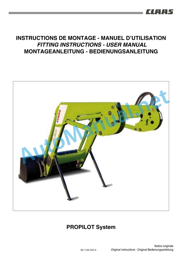
Claas Manubal (B96) Tractors Operator Manual EN
$50.00
- Model: Manubal (B96) Tractors
- Type Of Manual: Operator Manual
- Language: EN
- Format: PDF(s)
- Size: 24.2 MB
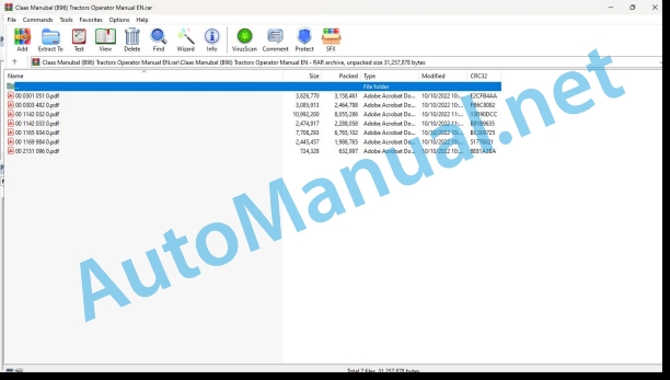
File List:
00 0301 051 0.pdf
00 0303 482 0.pdf
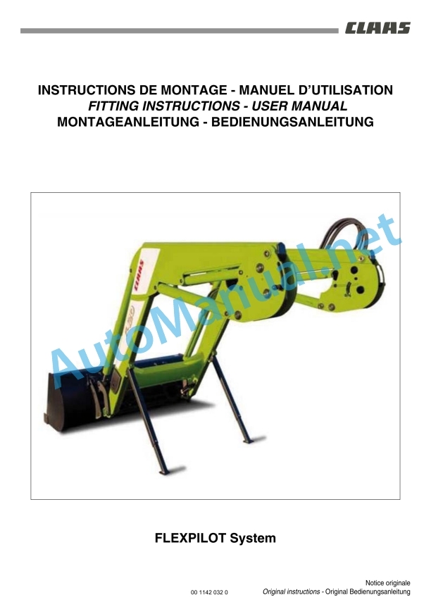
00 1142 032 0.pdf
00 1142 033 0.pdf
00 1165 934 0.pdf
00 1169 984 0.pdf
00 2151 096 0.pdf
00 0301 051 0.pdf:
PROFI CAM 3
Table of contents
1 Introduction
1.1 Notes on the manual
1.1.1 Validity of manual
1.1.2 Information about this Operator’s Manual
1.1.3 Symbols and notes
1.1.4 Optional equipment
1.1.5 Qualified specialist workshop
1.1.6 Maintenance information
1.1.7 Warranty notes
1.1.8 Spare parts and technical questions
1.2 Intended use
1.2.1 Intended use
1.2.2 Reasonably foreseeable misuse
2 Safety
2.1 Identifying warnings
2.1.1 Hazard signs
2.1.2 Signal word
2.2 Safety rules
2.2.1 Meaning of Operator’s Manual
2.2.2 Observing safety decals and warnings
2.2.3 Optional equipment and spare parts
3 Product description
3.1 Overview and method of operation
3.1.1 How the PROFI CAM works
3.2 Identification plates and identification number
3.2.1 Position of identification plates
3.2.2 Explanation of PROFI CAM identification plate
3.3 Information on the product
3.3.1 CE marking
4 Operating and control elements
4.1 Camera system
4.1.1 Camera system monitor
4.2 Menu structure
4.2.1 Main menu
4.2.2
4.2.3
4.2.4
4.2.5
4.2.6
5 Technical specifications
5.1 PROFI CAM
5.1.1 Monitor
5.1.2 Camera
5.1.3 Switch box
5.1.4 Degree of protection against foreign bodies and water
6 Preparing the product
6.1 Shutting down and securing the machine
6.1.1 Switching off and securing the machine
6.2 Prior to operation
6.2.1 Carry out prior to operation
6.2.2 Installing the sun protection
6.2.3 Aligning the camera
6.2.4 Connecting the camera electrics
7 Operation
7.1 Monitor
7.1.1 Switching on the monitor
7.1.2 Calling up the menu
7.1.3 Setting a menu item
7.1.4 Setting the image orientation
7.1.5 Setting automatic screen darkening
7.1.6 Image mirroring
7.1.7 Setting the trigger view
7.1.8 Setting the follow-up time for trigger view
7.1.9 Setting the display mode
7.1.10 Activating/deactivating a display mode
8 Faults and remedies
8.1 Electrical and electronic system
8.1.1 Overview of problems on PROFI CAM camera system
8.1.2 Replacing the switch box fuse
9 Maintenance
9.1 Maintenance intervals
9.1.1 Every 10 operating hours or daily
9.2 Camera system
9.2.1 Checking the camera system for dirt
9.2.2 Cleaning the camera
9.2.3 Cleaning the switch box
9.2.4 Cleaning the monitor
10 Placing out of operation and disposal
10.1 General Information
10.1.1 Putting out of operation and disposal
11 Technical terms and abbreviations
11.1 Abbreviations
11.1.1 Units
11.1.2 Abbreviations
11.1.3 Technical terms
00 0303 482 0.pdf:
PROFI CAM 4
Table of contents
1 Introduction
1.1 Notes on the manual
1.1.1 Validity of manual
1.1.2 Information about this Operator’s Manual
1.1.3 Symbols and notes
1.1.4 Optional equipment
1.1.5 Qualified specialist workshop
1.1.6 Maintenance information
1.1.7 Notes on warranty
1.1.8 Spare parts and technical questions
1.2 Intended use
1.2.1 Intended use
1.2.2 Reasonably foreseeable misuse
2 Safety
2.1 Identifying warnings
2.1.1 Hazard signs
2.1.2 Signal word
2.2 Safety rules
2.2.1 Meaning of Operator’s Manual
2.2.2 Structural changes
2.2.3 Optional equipment and spare parts
2.2.4 Operation only following proper putting into operation
2.2.5 Technical status
2.2.6 Respecting technical limit values
Respecting technical limit values
2.2.7 Hazards when driving on roads and fields
3 Product description
3.1 Overview and method of operation
3.1.1 How the PROFI CAM works
3.2 Identification plates and identification number
3.2.1 Identification plates
3.3 Information on the product
3.3.1 CE marking
4 Operating and display elements
4.1 Camera system
4.1.1 Camera system monitor
4.1.2 CEBIS
4.2 Menu structure
4.2.1 Main menu
4.2.2
4.2.3
4.2.4
4.2.5
4.2.6
5 Technical specifications
5.1 PROFI CAM
5.1.1 Monitor
5.1.2 Camera
5.1.3 Switch box
6 Preparing the product
6.1 Switching off and securing the machine
6.1.1 Switching off and securing the machine
6.2 Prior to putting into operation
6.2.1 Carry out prior to operation
6.2.2 Installing the sun protection
6.2.3 Aligning the camera
7 Operation
7.1 Monitor
7.1.1 Switching on the monitor
7.1.2 Calling up the menu
7.1.3 Setting a menu item
7.1.4 Setting the image orientation
7.1.5 Setting automatic screen darkening
7.1.6 Image mirroring
7.1.7 Setting the trigger view
7.1.8 Setting the follow-up time for trigger view
7.1.9 Setting the display mode
7.1.10 Activating/deactivating a display mode
8 Faults and remedies
8.1 Electric and electronic system
8.1.1 Overview of problems on PROFI CAM camera system
9 Maintenance
9.1 Maintenance intervals
9.1.1 Every 10 operating hours or daily
9.2 Camera system
9.2.1 Checking the camera system for dirt
9.2.2 Cleaning the camera
9.2.3 Cleaning the switch box
9.2.4 Cleaning the monitor
10 Putting out of operation and disposal
10.1 General information
10.1.1 Putting out of operation and disposal
11 Technical terms and abbreviations
11.1 Abbreviations
11.1.1 Units
11.1.2 Abbreviations
11.1.3 Technical terms
00 1165 934 0.pdf:
MANUBALC40-C30-U40L6000-L500-L40V7000-V500-V60-V50-V40W500
Table of contents
1 To this Operator’s Manual
1.1 Notes on the manual
1.1.1 Using the user manual
Important information concerning this user manual
Structure by MANUBAL sub-assemblies
Search and find
Direction indications
Specific terminology
Optional and additional equipment
1.1.2 Symbols and instructions
Text and illustrations
Highlighting dangers and warnings
1.1.3 Technical information
2 Safety
2.1 Safety instructions
2.1.1 Recommendations
2.1.2 Appropriate use
2.1.3 Inappropriate use
2.1.4 Safety and accident prevention instructions
2.1.5 MANUBAL
2.1.6 Checking the condition of the MANUBAL
2.1.7 Adjustment, servicing or repair work
2.1.8 Driving and transport
2.1.9 Safety regulations
2.1.10 Safety labels
3 Machine description
3.1 Identification plate and serial number
3.1.1 Identification plate
3.2 Overview
3.2.1 Description
Bale grabber
Wrapped bale grabber
Connections
Bale fork
3.3 Optional equipment
3.3.1 Wrapped bale grabber kit
3.3.2 Lower finger kit
3.3.3 Finger length
3.3.4 Additional fingers
3.3.5 Extension
4 Technical specifications
4.1 MANUBAL
4.1.1 Specifications of the MANUBAL bale grabber
4.1.2 Specifications of the MANUBAL bale fork
5 Machine preparation
5.1 Hitch
5.1.1 Hitching the MANUBAL
For an implement carrying frame with manual unlocking
5.1.2 Unhitching the MANUBAL
For an implement carrying frame with manual unlocking
5.2 Fieldwork settings
5.2.1 Adjusting the grabber opening/closing
Round bale
Rectangular bale
5.2.2 MANUBAL W500 2nd bale sensor
Operating principle
Adjusting the sensor
Forced activation of the sensor
5.2.3 MANUBAL C40 — Adjusting the Power control system
5.2.4 Position of bale fork fingers
Fixed fingers position
Floating fingers position
Inclined position
On-road position of foldable fingers
5.2.5 MANUBAL V7000 lower fingers
Configuration of lower fingers
Parking posion
5.2.6 Finger spacing
5.3 Optional equipment
5.3.1 Wrapped bale grabber kit
Adjusting the opening/closing of the wrapped bale grabber
Asseling the wrapped bale grabbers
5.3.2 Lower finger kit
Configuration of lower fingers
Parking position
Adjusting the finger spacing
5.3.3 Extension
6 Operation
6.1 MANUBAL
6.1.1 Picking up bales on cylindrical face
6.1.2 Picking up bales on flat face
6.2 MANUBAL V50
6.2.1 Changing the grabber position
7 Maintenance
7.1 Maintenance Information
7.1.1 Cleaning the MANUBAL
7.2 General maintenance information
7.2.1 Servicing and storage
Maintenance
7.3 Lubrication plan
7.3.1 Greasing
8 EC declaration of conformity
8.1 MANUBAL
8.1.1 MANUBAL C40, C30, L6000, L500, L40, U40, V7000, V500, V60, V50, V40, W500
00 1169 984 0.pdf:
Sensor case for tractors Stage IIIB, IV and VSensor case for tractors Stage IIIB, IV and VSensor case for Stage IIIB, IV and V tractors
Contents
1 Sensorkoffer – Sensor case – Sensor suitcase – Stage IIIB, IV & V
1.1 Auflistung Kofferinhalt
1.1 Listing case content
1.1 Presentation of the contents of the suitcase
00 2151 096 0.pdf:
CONTENTS
1. USER INSTRUCTIONS
2. SAFETY INSTRUCTIONS
3. SAFETY STICKERS
4. IDENTIFICATION PLATE
5. DOMAIN OF USE
6. OPERATING PRINCIPLES
7. TECHNICAL SPECIFICATIONS
DECLARATION OF CONFORMITY
John Deere Repair Technical Manual PDF
John Deere Repair Technical Manual PDF
New Holland Service Manual PDF
John Deere Repair Technical Manual PDF
John Deere Application List Component Technical Manual CTM106819 24AUG20
John Deere Repair Technical Manual PDF
John Deere DF Series 150 and 250 Transmissions (ANALOG) Component Technical Manual CTM147 05JUN98
John Deere Repair Technical Manual PDF
John Deere Repair Technical Manual PDF
John Deere Diesel Engines POWERTECH 2.9 L Component Technical Manual CTM126 Spanish
John Deere Repair Technical Manual PDF
John Deere 18-Speed PST Repair Manual Component Technical Manual CTM168 10DEC07
John Deere Repair Technical Manual PDF
John Deere Repair Technical Manual PDF

