Claas Torion 1914 (K59) Wheel Loaders Technical System EN
$300.00
- Model: Torion 1914 (K59) Wheel Loaders
- Type Of Manual: Technical System
- Language: EN
- Format: PDF(s)
- Size: 344 MB
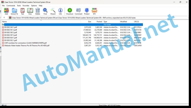
File List:
00 0302 343 1.pdf
00 0302 501 2.pdf
00 0302 565 2.pdf
00 0302 597 2.pdf
00 0303 924 1.pdf
00 0303 932 1.pdf
CHP-numbers for connectors CLAAS HARNESS PARTS.pdf
Webasto Water heater Thermo Pro 90 Thermo Pro 90 HDD.pdf
00 0302 343 1.pdf:
PROFI CAM 3
Table of contents
General information
Marking of warnings and hazard prevention notes
First-aid measures
CCN explanation
CCN (CLAAS Component Number)
Electric system standard
Overview
Hydraulic system standard
Overview
CCN (CLAAS Component Number)
10 Electrical / Electronic equipment
1030 Board computer / Indicators
Camera system
Description of function
1097 Testing / Measuring / Adjusting
Testing / measuring / adjusting the PROFI CAM
Checking the fuse in the video channel select box (C102)
Testing the video camera connector (C055)
1098 Fault / remedy
Fault / remedy PROFI CAM
The video monitor (C101) shows no image or cannot be switched on (indicator light fails to light up)
Video monitor (C102) displays a blue image either permanently or temporarily
The video monitor image is blurred
Replacing the fuse in the video channel select box (C102)
Connection and connecting cable with video camera (C055)
00 0302 501 2.pdf:
Liebherr LH-D934 A7/LH-D944 A7TIER 4
Table of contents
Introduction
Notes on the manual
Validity of manual
Abbreviations used in the documentation for the Liebherr diesel engine
Information about this Technical Systems Manual
Using the manual
Document structure based on subassemblies
Search and find
Directions
Identifying warnings
Hazard signs
Signal word
Safety rules
Safety signs and warnings
Requirement made on technical staff
Children in danger
Hazard areas of the machine
Instructors travelling along during fieldwork
Risk of injury due to rotating shafts
Structural alterations of the machine
Optional equipment and spare parts
Control of running machine
Technical condition
Respecting technical limit values
Danger from machine parts that continue rotating
Keeping safety devices functional
Personal protective equipment
Wearing suitable clothing
Removing dirt and loose objects
Parking the machine safely
Unsuitable operating utilities
Safe handling of service fluids and auxiliary utilities
Environmental protection and disposal
Keeping the cab free of chemicals
Avoiding fires
Potentially fatal electric shock from overhead lines and lightning strike
Electric shock from electric system
Noise may damage your health
Pre-loaded machine parts
Liquids under pressure
Compressed air
Toxic exhaust gases
Hot surfaces
Safe access and leaving
Working only on the stopped machine
Hazards during repairs
Raised machine parts and loads
Danger from welding work
Checking and charging the battery
Preparations for cases of emergency
CCN explanation
CCN (CLAAS Component Number)
Electric system standard
Overview
Hydraulic system standard
Overview
CCN (CLAAS Component Number)
01 Engine
0102 Complete component
Complete component
Engine components – view – flywheel side
Engine components – view – unit carrier – side
Type designations, serial numbers, information
Engine type designation
Engine company nameplate
Engine serial number
Engine serial number in engine company nameplate
Engine serial number in crankcase
Firing order, cylinder designation
Direction of rotation, cylinder and valve arrangement
TDC mark
Crankcase number
Connecting rod number (cracked connecting rod)
Turbocharger company nameplate
Injector identifier
High-pressure pump identifier
Engine control unit company nameplate
Piston number
General Information
0110 Engine housing
Basic engine
Cylinder designation and direction of rotation
0120 Cylinder head / Valves / Idler gear
Cylinder head – valves – gear train
Cylinder head – components
Cylinder head – components
Valve drive roller plunger
Gear train view
0125 Injection / Fuel system
Injection system/fuel system
Fuel diagram
Fuel system/supply
Fuel pre-filter (Separ)
Fuel level indicator (B25-LBH)
Diagram of the fuel system on the diesel engine
High-pressure fuel pump
Injection system graphic
Inlet connector
Injector
Diagram of cylinder head with injector
Venting the fuel system
Manual feed pump
Cleanliness of fuel system components
Cleanliness of the engine
Working environment
Tools that have to be used to achieve cleanliness when working on the fuel injection system: Warranty condition.
New Components
Refuelling
Diesel fuel
Diesel fuel specifications
Additional fuel requirements
Safety measures and information regarding the use of diesel fuel
0130 Lubricating oil system
Lubricating oil system
Lubricating oil diagram
Limit control valve (oil pressure control valve)
Checking the engine oil pressure
Inspecting excessive bearing wear
Engine Oil Leaks on the Outside of the Engine
Engine Oil Leaks into the Combustion Area of the Cylinders
Investigating increased engine oil temperature
0135 Cooling system
Cooling system
Coolant diagram
Engine coolant circuit
Coolant circuit on the unit carrier side
Cylinder head coolant circuit
Assignment of the channels in the crankcase and cylinder head
Thermostat installation position
0155 Engine control
Electronic Engine Control
Power reductions:
Power reduction when the coolant temperature is too high
Power reduction depending on the charge air temperature
Function of the exhaust brake
0165 Exhaust gas aftertreatment
SCR system exhaust gas aftertreatment
Complete overview of the SCR catalytic converter system
Structure of the SCR exhaust gas aftertreatment
Function of the SCR catalytic converter
Function overview of the SCR system
SCR system coolant heater
Urea injection
Exhaust throttle flap
Dosing unit
Dosing unit self-test with the ignition ON (terminal 15)
Dosing unit self-test with the diesel engine running
Blowing out the urea lines after switching off the diesel engine
Urea removal module
Exhaust gas aftertreatment sensors
NOx sensor
B783-LMB NH3 ammonia sensor
Exhaust gas aftertreatment with diesel particulate filter (optional)
Optional exhaust gas aftertreatment with diesel particulate filter
Functional diagram with diesel particulate filter
Load condition display
Load condition (load due to soot particles)
Load condition (time since the last manual regeneration)
Compressed-air system for exhaust gas aftertreatment
Complete overview of the compressed-air system
Compressed-air system: Schematic diagram
Air compressor
Air dryer
Valve for the SCR system’s compressed-air supply
0197 Test/Measurement/Setting
Checking and adjusting the valve clearance
Engine turning device
Cylinder arrangement, valves
Checking/adjusting the inlet valve clearance
Checking/adjusting the outlet valve clearance
Checking the engine oil pressure
Checking the engine oil pressure
Checking the B703-LMB sensor for charge air pressure
B703-LMB sensor for charge air pressure
Checking the B701-LMB oil pressure sensor
B701-LMB oil pressure sensor
Check fuel pressure sensor (B702-LMB)
B702-LMB sensor for fuel pressure
Checking the B707-LMB sensor for charge air temperature
B707-LMB sensor for charge air temperature
Checking the B708-LMB sensor for cooling water temperature
B708-LMB sensor for cooling water temperature
Checking the B709-LMB sensor for fuel temperature
B709-LMB sensor for fuel temperature
Checking the B704-LMB rail pressure sensor
B704-LMB rail pressure sensor
Check ambient temperature sensor (B737-LMB)
B737-LMB sensor for ambient temperature
Characteristic curve of the B737-LMB sensor for ambient temperature
Checking the B785-LMB air mass sensor
B785-LMB air mass sensor
Checking the B25-LBH fuel level indicator
Fuel level indicator (B25-LBH)
Inspection of the M715-LMB exhaust flap
Exhaust flap stop
Installation instructions for the B713-LMB and B711-LMB speed sensors
B713-LMB and B711-LMB speed sensors
Checking the urea solution
Work preparation
Special tool
Checking the urea solution (purity)
Checking the urea solution (density)
0198 Problem / Remedy
Fault – Cause – Remedy
Troubleshooting in the SCR system
SCR system fault tree
Troubleshooting according to the fault tree
10 Electrical / Electronic equipment
1000 General electrical system
Electrical components on the diesel engine
Electrical components on the right-hand side
Electrical components on the left-hand side
1012 Modules / sensors
Sensors on the diesel engine
B703-LMB sensor for charge air pressure
B701-LMB oil pressure sensor
B702-LMB sensor for fuel pressure
B707-LMB sensor for charge air temperature
B708-LMB sensor for cooling water temperature
B709-LMB sensor for fuel temperature
B704-LMB rail pressure sensor
B737-LMB sensor for ambient temperature
B785-LMB air mass sensor
1080 Electrical circuit diagram
LIEBHERR LH-934 A7/LH-944 A7 electric circuit diagrams
SCM 04 component position
SCM 05 engine side overview
SCM 08 socket X3 engine control C coding
SCM 09 socket X4 engine control D coding
SCM 10 alternator, starter, air conditioning compressor
SCM 11 heater flange, exhaust throttle flap, connector with terminating resistor
SCM 12 oil pressure sensor, fuel pressure sensor, charge air pressure sensor
SCM 13 charge air temperature sensor, cooling water temperature sensor, fuel temperature sensor
SCM 14 charge air cooler temperature sensor, PVG temperature sensor interface, wastegate control valve
SCM 15 engine oil level and temperature sensor, speed sensor, camshaft speed sensor
SCM 16 rail pressure sensor, VCV high-pressure pump, PCV high-pressure pump
SCM 17 injection nozzles
Socket X1 engine control A coding
Socket X2 engine control B coding
Heater flange relay 1
CAN bus interface 1
Cooling water level switch
A700-LMB supply
Urea heater
SCR compressed-air system
SCR dosing unit
Air mass sensor, NOx sensors
Urea tank, NH3 sensor
Diagnostics, diesel preheating option
Breakdown of wiring drawing according to circuit diagram
Example:
Breakdown of wire designation according to circuit diagram
Cable structure (cross-section)
Example wire designation
1085 Networks
Diesel engine CAN system
CAN system graphic
Key to diagram
92 Diagnosis
Diagnosis by fault codes
9220 Error codes engine (J1939)
FMI failure code (Failure Mode Indicator)
FMI fault code (Failure Mode Indicator) ISO (J1939)
FMI 00 (Signal too high)
FMI 01 (Signal too low)
FMI 02 (Erratic signal)
FMI 03 (Voltage too high)
FMI 04 (Voltage too low)
FMI 05 (Current too low)
FMI 06 (Current too high)
FMI 07 (Mechanical fault)
FMI 08 (Faulty frequency signal)
FMI 09 (Communication fault)
FMI 10 (Signal changes too quickly)
FMI 11 (Multiple fault)
FMI 12 (ECU defective)
FMI 13 (Signal outside of calibration range)
FMI 16 (Parameter not available)
FMI 17 (No reply from ECU)
FMI 18 (Power supply fault)
FMI 19 (Software conditions not met)
Fault codes
Diesel engine fault codes – Liebherr LH-D934 A7/LH-D944 A7
Description of function
Fault code
00 0302 565 2.pdf:
Sensor system
Table of contents
CCN explanation
CCN (CLAAS Component Number)
Electric system standard
Overview
Hydraulic system standard
Overview
CCN (CLAAS Component Number)
Introduction
Safety rules
Safety and hazard information
10 Electrical / Electronic equipment
1097 Testing / Measuring / Adjusting
Test report of the angle sensor (0011780.x)
Application of test report
Required tools
Test report of the angle sensor (0011780.x)
Testing / Measuring / Adjusting of angle sensor (0011780.x)
1. Reason for test
2. Mechanical test of angle sensor
3. Electric test with CDS
4. Electric test with multimeter
5. Mechanical test of connecting cable
Completing the machine
Test report of position and speed sensors
Application of test report
Required tools
Sensor variants
Part numbers of speed sensors
Part number of position sensor
Test report of position and speed sensors
Testing / measuring / adjusting of position and speed sensors
1. Reason for test
2. Mechanical test
3. Electric test with CDS
4a. Installation dimensions
Check of installation dimension
Installation dimensions of gearbox speed sensor (0011 799.x) and cam speed sensor (0011 810.x)
Installation dimension of position sensor (0011 815.x)
4b. Installation position
Centring of sensor
Metal-free zone
5. Electric test with multimeter
Voltage measurement
Direction of rotation and speed sensor (0011 605.x)
Measured values table
6. Mechanical test of connecting cable
Completing the machine
Test report of the urea sensor (00 0773 207 x)
Application of test report
Required tools
Parts number of the urea sensor
Test report of the urea sensor
Testing / measuring / adjusting urea sensor
1. Reason for test
2. Mechanical test
3. Mechanical test of connecting cable
4. Electric test with multimeter
5. Component test with the CDS
00 0302 597 2.pdf:
TORION 1812TORION 1914
Table of contents
Introduction
Notes on the manual
Validity of manual
Information about this Technical Systems Manual
Using the manual
Document structure based on subassemblies
Search and find
Directions
Identifying warnings
Hazard signs
Signal word
Safety rules
Safety signs and warnings
Requirement made on technical staff
Children in danger
Hazard areas of the machine
Instructors travelling along during fieldwork
Risk of injury from rotating shafts
Structural alterations of the machine
Optional equipment and spare parts
Control of running machine
Technical condition
Respecting technical limit values
Danger from machine parts that continue rotating
Keeping safety devices functional
Personal protective equipment
Wearing suitable clothing
Removing dirt and loose objects
Parking the machine safely
Unsuitable operating utilities
Safe handling of service fluids and auxiliary utilities
Environmental protection and disposal
Keeping the cab free of chemicals
Avoiding fires
Potentially fatal electric shock from overhead lines and lightning strike
Electric shock from electric system
Noise may damage your health
Pre-loaded machine parts
Liquids under pressure
Compressed air
Toxic exhaust gases
Hot surfaces
Safe access and leaving
Working only on the stopped machine
Hazards during repairs
Raised machine parts and loads
Danger from welding work
Checking and charging the battery
Preparations for cases of emergency
CCN explanation
CCN (CLAAS Component Number)
Electric systems standard
Overview
Hydraulic system standard
Overview
CCN (CLAAS Component Number)
01 Engine
0135 Cooling system
Variable cooling fan
Without fan reversing
With fan reversing
Measured values table
Description of function
0150 Engine attachment parts
Starting the diesel engine, accelerator pedal, fuel sensor
Measured values table
Description of function
0155 Engine control
Electronic Engine Control
0165 Exhaust gas aftertreatment
Exhaust gas treatment
0197 Test/Measurement/Setting
Engine and cooling test protocol
Important notes and preparation
Test protocol
Testing and adjusting the cooling system hydraulics
Testing the fan solenoid valve
Maximum operating pressure
Checking the pressure limitation upon failure of fan solenoid valve
03 Chassis
0335 Ground drive
Measured values table
Description of function
Overview
Power flow of gearbox
Hydraulics of gearbox and of hydrostatic module
DYNAMIC POWER
Measured values table
Description of function
0397 Testing / measuring / adjusting
Ground drive test protocol
Important notes and preparation
Test protocol
Testing and adjusting the ground drive
Adjusting the pedals
Performing the basic gearbox adjustment
Adjustment of hydrostatic unit
Basic adjustment of clutch
Performing the service adjustment of the gearbox
Adjustment of hydrostatic unit
Service adjustment of clutch
Checking the ground drive performance
04 Brake
0400 Brake
Brake system
Measured values table
Description of function
0497 Testing / measuring / adjusting
Brake system test protocol
Important notes and preparation
Test protocol
Testing and adjusting the brake system
05 Steering
0505 Steering
Steering system with emergency steering
Description of function
Joystick steering
Measured values table
Description of function
Reactive joystick steering
Dynamic steering
Measured values table
Description of function
Steering pump
Description of function
0597 Testing / measuring / adjusting
Steering system test protocol
Important notes and preparation
Test protocol
Testing and adjusting the steering system
Steering pump
LS pressure cut-off
Flow rate controller
Steering dampening
Checking the steering attenuation hydraulic accumulator
Joystick steering
Joystick steering: determine the installation position of position sensors
Adjusting the articulated joint sensor
Adjusting the joystick steering main spool
Adjusting the joystick steering emergency spool
Adjusting the start of steering system movement
06 Lift device
0630 Lift arms
Working attachment
Measured values table
Description of function
0697 Testing / measuring / adjusting
Working hydraulics test protocol
Important notes and preparation
Test protocol type K58
Test protocol type K59
Testing and adjusting the working hydraulics
Adjusting the multi-lever control unit
Adjusting the lift arms angle sensors
Testing and adjusting the working hydraulics pump
Flow rate controller
Delivery controller
Working hydraulics control block
Proportional valves
Automatic adjustment of proportional valves for lift and tipping functions
Manual adjustment of proportional valves for 3rd and 4th function
Checking the pressure reduction valve in the pilot control valve block
Secondary pressure relief valves
Primary pressure relief valve
LS pressure cut-off
Stabilisation module
Testing the shut-off function
Testing the vibration damping hydraulic accumulator
Quick-hitch plate
Testing the pressure reduction valve
09 Hydraulic system
0910 Pumps
Working hydraulics pump
Description of function
0920 Valves
Working hydraulics control block
Measured values table
Description of function
Working hydraulics pilot control solenoid valve
Description of function
Stabilisation module
Description of function
Fan reversing valve block
Orbitrol steering unit
Description of function
Dynamic steering
Description of function
Steering stabilisation valve block
Description of function
Joystick steering control block
Validity: K5800011 to K5800072, K5900011 to K5900061
Description of function
Validity: from K5800073, from K5900062
Description of function
Compact brake valve
Description of function
0980 Hydraulic circuit diagram
Cooling system hydraulic circuit diagram
Cooling system without reversing fan
Cooling system with reversing fan
Gearbox hydraulic circuit diagram
Brake hydraulic circuit diagram
Steering hydraulic circuit diagram
Dynamic steering hydraulic circuit diagram
Joystick steering hydraulic circuit diagram
Validity: K5800011 to K5800072, K5900011 to K5900061
Validity: from K5800073, from K5900062
Z linkage working hydraulics circuit diagram
Agrar linkage working hydraulics circuit diagram
Pipe break protection device hydraulic circuit diagram
0997 Testing / measuring / adjusting
Testing the hydraulic accumulator nitrogen filling
10 Electrical / Electronic equipment
1005 Power supply
Earth points
1010 Central electrics
Cab main board – A4-LBH
Key to diagram
Fuse assignment
Relay assignment
Outer main board – A4a-LBH
Key to diagram
Fuse assignment
Relay assignment
1012 Modules / sensors
Module A11-LBH – Main keyboard
Key to diagram
Key to diagram
Module A13-LBH – Display unit
Key to diagram
Key to diagram
Module A15-LBH – Master control unit master 5
Key to diagram
Key to diagram
Module A16a-LBH – Input module 1
Key to diagram
Key to diagram
Signal types of input modules
Addresses of input modules
Module A16b-LBH – Additional input module 1
Key to diagram
Key to diagram
Signal types of input modules
Addresses of input modules
Module A17a-LBH – Output module 1
Key to diagram
Key to diagram
Signal types of output modules
Addresses of output modules
Module A17b-LBH – Additional output module 1
Key to diagram
Key to diagram
Signal types of output modules
Addresses of output modules
Module A21-LBH – Heater / air conditioner
Key to diagram
Key to diagram
Module A23-LBH – Weighing unit control unit
Key to diagram
Key to diagram
Module A25-LBH – Gearbox
Key to diagram
Key to diagram
Module A26-LBH – Pilot sensor
Key to diagram
Key to diagram
Module A29-LBH – Joystick steering
Key to diagram
Key to diagram
1080 Electrical circuit diagram
Introduction into electric circuit diagrams
Electric circuit diagrams of machine (SCM)
SCM 22 – Ignition switch, batteries, alternator
Key to diagram
SCM 23 – Emergency steering pump
Key to diagram
SCM 24 – Road travel switch
Key to diagram
SCM 25 – Interior lights, compressor seat, door contact switch
Key to diagram
SCM 27 – Steering column switch, brake light, registration plate lighting
Key to diagram
SCM 28 – Hazard warning flasher function
Key to diagram
SCM 29 – Front cab roof work light
Key to diagram
SCM 30 – Rear work light
Key to diagram
SCM 31 – Front windscreen washer system, horn
Key to diagram
SCM 32 – Rear windscreen washer system
Key to diagram
SCM 33 – Warning beacon, rear window heater
Key to diagram
SCM 34 – Cigarette lighter, 12 V socket, broadcast receiver
Key to diagram
SCM 35 – Camera
Key to diagram
SCM 36 – CAN BUS 1, CAN BUS 4
Key to diagram
SCM 37 – Display unit, CAN BUS 3
Key to diagram
SCM 38 – Pilot sensor, CAN BUS 2
Key to diagram
SCM 39 – Working hydraulics pilot pressure, vibration damping, position control
Key to diagram
SCM 40 – Working hydraulics solenoid valves
Key to diagram
SCM 41 – Main keyboard, gearbox, parking brake power supply
Key to diagram
SCM 42 – Gearbox
Key to diagram
SCM 43 – Power supply of input module 1 and output module 1 logics
Key to diagram
SCM 44 – Power supply of output module 1 load
Key to diagram
SCM 45 – Fuel level sensor, hydraulic oil temperature
Key to diagram
SCM 46 – Service access, buzzer, master power supply switches
Key to diagram
SCM 47 – Engine control unit power supply
Key to diagram
SCM 48 – SCR Temperature and pressure sensors
Key to diagram
SCM 49 – SCR Hose heater and water valves
Key to diagram
SCM 50 – SCR compressed air compressor and drier
Key to diagram
SCM 51 – SCR dosing module
Key to diagram
SCM 52 – Diesel engine air mass sensor and NOx sensors
Key to diagram
SCM 53 – Diesel engine urea tank and NH3 sensor
Key to diagram
SCM 54 – Diesel engine power supply
Key to diagram
SCM 55 – Accelerator pedal and inching pedal angle sensors
Key to diagram
SCM 56 – Air conditioner – machine side
Key to diagram
SCM 57 – Air conditioner condenser fan
Key to diagram
SCM 58 – Air conditioner – system side
Key to diagram
SCM 59 – Diesel engine pre-heating and engine control diagnostic plug
Key to diagram
SCM 61 – Electric engine bonnet opening
Key to diagram
SCM 62 – Central lubrication system
Key to diagram
SCM 79 – Rear cab roof work light option
Key to diagram
SCM 80 – Front work light on light bracket option
Key to diagram
SCM 81 – Optical back-up warning system option
Key to diagram
SCM 82 – Acoustic back-up warning system and obstacle detector option
Key to diagram
SCM 83 – Horn actuation by additional pushbutton option
Key to diagram
SCM 84 – Electric mirror adjustment option
Key to diagram
SCM 85 – Refuelling pump and 24 V external socket option
Key to diagram
SCM 86 – CAN BUS 2 with additional modules option
Key to diagram
SCM 87 – Additional modules power supply option
Key to diagram
SCM 88 – Joystick steering option CAN BUS 2
Key to diagram
SCM 89 – Joystick steering option CAN BUS 3
Key to diagram
SCM 90 – Joystick steering CAN BUS option
Key to diagram
SCM 91 – Joystick steering power supply option
Key to diagram
SCM 92 – Joystick steering sensors I option
Key to diagram
SCM 93 – Joystick steering relay circuit power supply and arm rest switch option
Key to diagram
SCM 94 – Joystick steering sensors II option
Key to diagram
SCM 95 – Joystick steering safety circuit including dynamic steering option
Key to diagram
SCM 96 – Dynamic steering without joystick steering option
Key to diagram
SCM 97 – Joystick steering valves option
Key to diagram
SCM 99 – Quick-hitch plate option
Key to diagram
SCM 100 – Delayed automatic shut-off option
Key to diagram
SCM 102 – Additional heater option
Key to diagram
SCM 103 – Jump leads 24 V option
Key to diagram
SCM 104 – CB radio preparation options
Key to diagram
SCM 106 – Safety belt switch option
Key to diagram
SCM 107 – 3-point safety belt option
Key to diagram
SCM 108 – Weighing unit option
Key to diagram
SCM 109 – Weighing unit proximity switch option
Key to diagram
SCM 112 – Lighting control option
Key to diagram
SCM 113 – Articulated joint lighting control option
Key to diagram
SCM 115 – LED drive lights option
Key to diagram
SCM 116 – Country-specific version option
Key to diagram
SCM 120 – OBD connector and telemetry system
Key to diagram
SCM 122 – Variant 1 multi-lever control input module M
Key to diagram
SCM 123 – Variant 1 multi-lever control
Key to diagram
SCM 124 – Variant 1 multi-lever control
Key to diagram
SCM 126 – Variant 1 multi-lever control direction of travel
Key to diagram
SCM 128 – Variant 1 multi-lever control start switch
Key to diagram
SCM 129 – Variant 1 multi-lever control immobiliser horn
Key to diagram
1085 Networks
CAN-BUS and Ethernet
Description of function
12 Cab / Operator’s platform
1240 Air condition
Heating, ventilation, air conditioner
Measured values table
Description of function
75 Central lubrication system
7505 Reservoir / Pump
Central lubrication system
Description of function
7515 Lubrication system / Lines
Grease distribution
Z linkage grease distribution
Agrar linkage grease distribution
92 Diagnosis
9210 Error codes machine
Machine fault codes (DTC)
9298 Fault and remedy
Fault description of reversing obstacle warning device
Position of components
Hydraulic system
1001-1999 Oil tank / filter / cooler
2001-2999 Pump / motor
3001-3999 Hydraulic cylinders
5001-5999 Accumulator
6001-6999 Valves – mechanically actuated (hydraulic system)
7001-7999 Valves – hydraulically actuated
8001-8999 Couplings / connections
9001-9999 Measuring points / gauges
Electric system
A Terminal / modules
B Sensors / loudspeakers
E Lighting
G Voltage sources
H Signal device / light
K Relays
S Switch / pushbutton – Cab operation
T Voltage transformer
W Antenna
X Connectors
Y Solenoid coils
00 0303 924 1.pdf:
Technical systems
Table of contents
Introduction
Notes on the manual
Validity of manual
Information about this Technical Systems Manual
Using the manual
Document structure based on subassemblies
Search and find
Directions
Identifying warnings
Hazard signs
Signal word
Safety rules
Safety signs and warnings
Requirement made on technical staff
Children in danger
Hazard areas of the machine
Instructors travelling along during fieldwork
Risk of injury from rotating shafts
Structural alterations of the machine
Optional equipment and spare parts
Control of running machine
Technical condition
Respecting technical limit values
Danger from machine parts that continue rotating
Keeping safety devices functional
Personal protective equipment
Wearing suitable clothing
Removing dirt and loose objects
Parking the machine safely
Unsuitable operating utilities
Safe handling of service fluids and auxiliary utilities
Environmental protection and disposal
Keeping the cab free of chemicals
Avoiding fires
Potentially fatal electric shock from overhead lines and lightning strike
John Deere Repair Technical Manual PDF
John Deere DF Series 150 and 250 Transmissions (ANALOG) Component Technical Manual CTM147 05JUN98
John Deere Repair Technical Manual PDF
John Deere Repair Technical Manual PDF
John Deere 18-Speed PST Repair Manual Component Technical Manual CTM168 10DEC07
John Deere Repair Technical Manual PDF
John Deere Repair Technical Manual PDF
John Deere PowerTech M 10.5 L and 12.5 L Diesel Engines COMPONENT TECHNICAL MANUAL CTM100 10MAY11
John Deere Parts Catalog PDF
John Deere Harvesters 8500 and 8700 Parts Catalog CPCQ24910 Spanish
John Deere Repair Technical Manual PDF
John Deere Repair Technical Manual PDF
John Deere Repair Technical Manual PDF
John Deere 16, 18, 20 and 24HP Onan Engines Component Technical Manual CTM2 (19APR90)
John Deere Repair Technical Manual PDF

