Claas Quadrant 5200 (J31) Baler Technical System ES
$300.00
- Model: Quadrant 5200 (J31) Baler
- Type Of Manual: Technical System
- Language: ES
- Format: PDF(s)
- Size: 172 MB
File List:
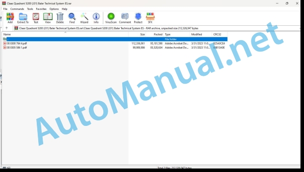
00 0300 764 4.pdf
00 0305 586 1.pdf
00 0300 764 4.pdf:
QUADRANT 5200
Introduction
Safety instructions
Safety and hazard instructions
Signage of warning and danger indications
Manual validity
Manual validity
CCN Explanation
CCN (CLAAS Component Number)
General indications
Electrical regulations
Hydraulic regulations
CCN (CLAAS Component Number)
04 Brake
0410 Trailed machine service brake
Hydraulic service brake
single axis
tandem axle
Pneumatic service brake
single axis
tandem axle
Trailer brake valve, two-pipe brake
Function Description
Check and adjustment
08 Drives
0808 Main drive
Main drive
Table of measured values
Function Description
09 Hydraulics
0900 General instructions for the hydraulic installation
External oil supply with cut-off device (RC/FC)
Constant current hydraulic installation connection
Function Description
Constant pressure hydraulic system connection
Function Description
Load Sensing connection with Power Beyond
Function Description
External oil supply without cutting device (RF)
Constant current hydraulic installation connection
Function Description
Constant pressure hydraulic system connection
Function Description
Load Sensing connection with Power Beyond
Function Description
0910 Bombs
Pumps, baling pressure and working hydraulic system
Table of measured values
0920 Valves
Valve block regulating baling pressure and carrier control
Table of measured values
Valve block of the external working hydraulic system with cutting device (RC/FC)
Valve block for external working hydraulic installation without cutting device (RF)
Pickup raise/lower valve block
Function Description
Pickup drive valve block
Actuated pusher valve block
Table of measured values
0980 Hydraulic connection diagram
QUADRANT 5200 RC/FC hydraulic connection diagrams
QUADRANT 5200 RC/FC without hydraulic pickup
QUADRANT 5200 RC/FC with hydraulic pickup up to J3100400
QUADRANT 5200 RC/FC with hydraulic pickup from J3100401
QUADRANT 5200 RF hydraulic connection diagrams
QUADRANT 5200 RF without hydraulic pickup and without bale ejector
QUADRANT 5200 RF without hydraulic pickup
QUADRANT 5200 RF with hydraulic pickup up to J3100400
QUADRANT 5200 RF with hydraulic pickup from J3100401
10 Install. electrical/electronic
1005 Power supply
Main voltage supply
Table of measured values
Function Description
1012 Modules / sensors
Module occupancy
A020 CLAAS CONTROL UNIT Module
Module occupancy
A195 Baling pressure adjustment module
Module occupancy
A204 System module for weighing bales
1040 Performance Measurement
Stem humidity sensor
Table of measured values
Function Description
Bale weighing system
Function Description
1080 Electrical connection diagram
Introduction of connection diagrams
Summary of denominations
Name of CLAAS cables
Power supply
Actuator system
sensory system
Communication
Standards
Electrical installation connection diagrams
SCM00a: Retrofit kit on the tractor for power supply via ISOBUS socket
SCM00b: Cable Y tractor – baler
SCM01: Main voltage supply, CAN-Bus and diagnostics
SCM02: CCU module and pickup drive
SCM03: Electromagnetic coils of the external working hydraulic installation
SCM04: Electromagnetic coils for baling pressure control and carrier control, tying trigger, air guide plate adjustment, service socket box
SCM05: Sensors for drive and conveyor revolutions, filling chamber, thread breakage, oil level
SCM06: Baling piston load indicator, flywheel brake sensor, cutting floor sensor, rotor, central lubrication system
SCM07: Knife drawer sensors
SCM08: Bale ramp sensors, bale ejector management and bale ramp
SCM09: Blade drawer management
SCM10: Baling pressure sensors, tying control, bale length and bale humidity, carrier control
SCM11 to J3100315: Baling pressure adjustment / working lighting module
SCM11 from J3100316: Bale pressure adjustment module / work lighting and bale weighing system
SCM12: Sensors for baling pressure adjustment and knotter control
SCM13: Work lighting
SCM14: Front and side lighting
SCM15a: Rear lighting
1081 Plug summary
Socket database (chp CLAAS)
Example of key number representation (CHP)
Key number (CHP)
Plug Representation (CHP)
1085 Networks
Table of measured values
Function Description
1097 Check/measure/adjust
sensory system
20 Reception of the harvest
2020 Pickup
Table of measured values
Function Description
Adjustment
21 Power set
2125 Rotor
Feeding automation and cutting device
Table of measured values
Function Description
Adjustment
Cutting bottom process diagram, rotor overload
Process diagram for activating ROTOCUT, including blade cleaning and rotor overload
Process diagram for deactivating ROTOCUT, including blade cleaning
Automatic process diagram for changing blades
2130 Carrier
Carrier control
Table of measured values
Function Description
Graphic: modulation of the filling chamber lid (Y245)
Carrier control table
The carrier control cylinder engages
Function Description
The conveyor control cylinder comes out, feeding the filling chamber
Function Description
Carrier control cylinder blocked, filling path in bale chamber
Function Description
45 Pressing device
4500 Crimping device
Baling pressure adjustment
Table of measured values
Function Description
Automatic baling pressure control
Graphic: Schematic representation of automatic baling pressure control
Adjustment
Baling piston load indicator (up to CCU software version 1.2.0)
Table of measured values
Function Description
Adjustment
Baling piston load indicator (as of CCU software version 1.3.0)
Table of measured values
Function Description
46 Tying system
4610 Thread tying
Tying system
Table of measured values
Function Description
Adjustment
Diagram of tied process and fault control
60 Deposit the material / deposit the straw
6040 Bale unloading
RC/FC bale unloading
Table of measured values
Function Description
Bale ramp sensor adjustment
RF bale unloading
Table of measured values
Function Description
Bale ramp sensor adjustment
75 Central lubrication
7505 Container, pump
Electric central lubrication system
Table of measured values
Function Description
7515 Lubrication/piping equipment
Central lubrication system, grease distribution (up to J3100456)
Central lubrication system, grease distribution (from J3100457)
Chain lubrication
Function Description
Verification
92 Diagnosis
9210 Machine Error Codes
List of machine fault codes (DTC)
DTC (Diagnostic Trouble Code) Summary
FMI error codes
General indications
FMI 00 (signal too large)
FMI 01 (signal too small)
IMF 02 (implausible signal)
FMI 03 (voltage too high)
FMI 04 (voltage too low)
FMI 05 (current too low)
FMI 06 (current too high)
FMI 07 (mechanical failure)
FMI 08 (frequency signal defective)
IMF 09 (communication failure)
FMI 10 (signal change too fast)
IMF 11 (multiple failure)
FMI 12 (defective ECU)
FMI 13 (signal outside calibration range)
IMF 16 (non-existent parameter)
FMI 17 (ECU not responding)
FMI 18 (power supply failure)
FMI 19 (software requirements not met)
IMF 95 (no signal change)
FMI 96 (CAN-Bus system defective)
IMF 97 (implausible state)
IMF 98 (warning)
IMF 99 (Info)
Location of components
Electrical installation
To Terminal/modules
B Sensors
and lighting
K Relays
M Motor (electric)
R Potentiometers/resistors
U Switch – external operation
V Electronic part
X Pluggable connections
and electromagnetic coil
Z Effective value switch
Hydraulic installation
1001-1999 Oil tank/filter/oil radiator
2001-2999 Pump/motor
3001-3999 Hydraulic Cylinder
4001-4999 Choke / Calibrated Orifice
5001-5999 Pressure accumulator
6001-6999 Mechanically Actuated Valve
7001-7999 Hydraulic Actuated Valve
9001- 9999 Measuring points / indicating instruments
00 0305 586 1.pdf:
QUADRANT 5200
Introduction
Information regarding the instruction manual
Manual validity
Information regarding this technical systems manual
Using the manual
Structuring with construction group structure
Search and find
Direction signs
Security
Recognize warning signs
Danger symbols
Safety instructions
Graphic danger symbols and warning indications
Requirements for technical personnel
Children in danger
Machine danger zones
Accompanying instructor during work
Risk of injury due to rotating shafts
Construction modifications to the machine
Optional equipment and spare parts
Control of the machine running
Technical status
Comply with technical limit values
Danger from machine parts during coasting
Keep protective devices operational
Personal protective equipment
Wear appropriate clothing
Remove dirt and loose objects
Park the machine safely
Unsuitable consumables
Safe handling of consumables and auxiliary materials
Environmental protection and waste disposal
Keep the cabin free of chemicals
Fire prevention
Lethal electrical shock due to overhead power lines and lightning strikes
Current discharge through the electrical installation
Noise can cause health damage
Prestressed machine parts
Liquids under pressure
Air under presure
Toxic exhaust gases
Hot surfaces
Safe ascent and descent
Only work on the stopped machine
Dangers in repair work
Machine parts and lifted loads
Danger from welding work
Check and charge the battery
Emergency Preparations
CCN Explanation
CCN (CLAAS Component Number)
General indications
Electrical regulations
Hydraulic regulations
CCN (CLAAS Component Number)
04 Brake
0410 Trailed machine service brake
Hydraulic service brake
single axis
tandem axle
Pneumatic service brake
single axis
tandem axle
Trailer brake valve, two-pipe brake
Function Description
Check and adjustment
08 Drives
0808 Main drive
Main drive
Table of measured values
Function Description
09 Hydraulics
0900 General instructions for the hydraulic installation
External oil supply with cutting device
Constant current hydraulic installation connection
Function Description
Constant pressure hydraulic system connection
Function Description
Load Sensing connection with Power Beyond
Function Description
0910 Bombs
Pumps, baling pressure and working hydraulic system
Table of measured values
0920 Valves
Valve block regulating baling pressure and carrier control
Table of measured values
Valve block for external working hydraulic installation without hydraulic pickup
Valve block external working hydraulic installation with hydraulic pickup
Pickup raise/lower valve block
Function Description
0980 Hydraulic connection diagram
QUADRANT 5200 hydraulic connection diagrams
QUADRANT 5200 without hydraulic pickup
QUADRANT 5200 with hydraulic pickup
OPTION Hydraulically foldable feeler wheels
10 Install. electrical/electronic
1005 Power supply
Main voltage supply
Table of measured values
Function Description
1012 Modules / sensors
Module occupancy
A020 CLAAS CONTROL UNIT Module
Module occupancy
A195 Baling pressure adjustment module
Module occupancy
A204 System module for weighing bales
1040 Performance Measurement
Stem humidity sensor
Table of measured values
Function Description
Bale weighing system
Function Description
1080 Electrical connection diagram
Introduction of connection diagrams
Summary of denominations
Name of CLAAS cables
Power supply
Actuator system
sensory system
Communication
Standards
Electrical installation connection diagrams
SCM00a: Retrofit kit on the tractor for power supply via ISOBUS socket
SCM00b: Cable Y tractor – baler
SCM01: Main voltage supply, CAN-Bus and diagnostics
SCM05: Filling chamber sensors, thread breakage
SCM06: Flywheel brake sensor, cutting depth sensor, rotor, central lubrication system
SCM07: Knife drawer sensors
SCM09: Blade drawer management
SCM 10: CCU module, pickup drive, drive and hauler revolutions, oil level, electromagnetic coils, external working hydraulic system
SCM 11: Baling pressure adjustment module / work lighting and bale weighing system
SCM12: Sensors for baling pressure adjustment and knotter control
SCM13: Work lighting
SCM14: Front and side lighting
SCM15a: Standard rear lighting
SCM 20: Bale pressure control and carrier control, tying trigger, bale length, air guide plate adjustment, service socket box
SCM 30: Bale ramp and bale humidity sensors, bale ejector handling and bale ramp
SCM 50: Chain lubrication oil level actual value switch option
1081 Plug summary
Socket database (chp CLAAS)
Example of key number representation (CHP)
Key number (CHP)
Plug Representation (CHP)
1085 Networks
Table of measured values
Function Description
1097 Check/measure/adjust
sensory system
20 Reception of the harvest
2020 Pickup
Table of measured values
Function Description
Pickup with hydraulically foldable feeler wheels
Table of measured values
Function Description
2097 Check/measure/adjust
Check and adjust material pickup
Pickup drive
Pickup rpm calibration
21 Power set
2125 Rotor
Feeding automation and cutting device
Table of measured values
Function Description
Adjustment
Cutting bottom process diagram, rotor overload
Process diagram for activating ROTOCUT, including blade cleaning and rotor overload
Process diagram for deactivating ROTOCUT, including blade cleaning
Automatic process diagram for changing blades
2130 Carrier
Carrier control
Table of measured values
Function Description
Graphic: modulation of the filling chamber lid (Y245)
Carrier control table
The carrier control cylinder engages
Function Description
The conveyor control cylinder comes out, feeding the filling chamber
Function Description
Carrier control cylinder blocked, filling path in bale chamber
Function Description
45 Pressing device
4500 Crimping device
Baling pressure adjustment
Table of measured values
Function Description
Automatic baling pressure control
Graphic: Schematic representation of automatic baling pressure control
Adjustment
Baling piston load indicator (as of CCU software version 1.3.0)
Table of measured values
Function Description
46 Tying system
4610 Thread tying
Tying system
Table of measured values
Function Description
Adjustment
Diagram of tied process and fault control
60 Deposit the material / deposit the straw
6040 Bale unloading
Bale unloading
Table of measured values
Function Description
Bale ramp sensor adjustment
75 Central lubrication
7505 Container, pump
Electric central lubrication system
Table of measured values
Function Description
7515 Lubrication/piping equipment
Central lubrication system, grease distribution (from J3100457)
Chain lubrication without hydraulic pickup
Function Description
Verification
Chain lubrication with hydraulic pickup
Function Description
Adjust the amount of oil
Verification
92 Diagnosis
9210 Machine Error Codes
List of Machine Error Codes (DTC)
DTC (Diagnostic Trouble Code) Summary
FMI error codes
General indications
FMI 00 (signal too large)
FMI 01 (signal too small)
IMF 02 (implausible signal)
FMI 03 (voltage too high)
FMI 04 (voltage too low)
FMI 05 (current too low)
FMI 06 (current too high)
FMI 07 (mechanical failure)
FMI 08 (frequency signal defective)
IMF 09 (communication failure)
FMI 10 (signal change too fast)
IMF 11 (multiple failure)
FMI 12 (defective ECU)
FMI 13 (signal outside calibration range)
IMF 16 (non-existent parameter)
FMI 17 (ECU not responding)
FMI 18 (power supply failure)
FMI 19 (software requirements not met)
IMF 95 (no signal change)
FMI 96 (CAN-Bus system defective)
IMF 97 (implausible state)
IMF 98 (warning)
IMF 99 (Info)
Location of components
Electrical installation
To Terminal/modules
B Sensors
and lighting
K Relays
M Motor (electric)
R Potentiometers/resistors
U Switch – external operation
V Electronic part
X Pluggable connections
and electromagnetic coil
Z Actual value switch
Hydraulic installation
1001-1999 Oil tank/filter/oil radiator
2001-2999 Pump/motor
3001-3999 Hydraulic Cylinder
5001-5999 Pressure accumulator
6001-6999 Mechanically Actuated Valve
7001-7999 Hydraulic Actuated Valve
9001- 9999 Measuring points / indicating instruments
John Deere Repair Technical Manual PDF
New Holland Service Manual PDF
John Deere Repair Technical Manual PDF
John Deere Repair Technical Manual PDF
John Deere Repair Technical Manual PDF
John Deere 16, 18, 20 and 24HP Onan Engines Component Technical Manual CTM2 (19APR90)
John Deere Repair Technical Manual PDF
John Deere Repair Technical Manual PDF
John Deere Parts Catalog PDF
John Deere Tractors 7500 Parts Catalog CPCQ26568 30 Jan 02 Portuguese
John Deere Repair Technical Manual PDF


