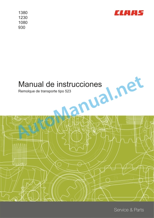
Claas Cutterbar Trailer 12,3M-9,3M (523) Combines Operator Manual ES
$50.00
- Model: Cutterbar Trailer 12,3M-9,3M (523) Combines
- Type Of Manual: Operator Manual
- Language: ES
- Format: PDF(s)
- Size: 11.8 MB
File List:
Document_1546_006_es.pdf
Document_1546_006_es.pdf:
138012301080930
1. Introduction
1.1 Information on the instruction manual
1.1.1 Validity of the manual
1.1.2 Information relating to this instruction manual
1.1.3 Symbols and indications
1.1.4 Qualified specialized workshop
1.1.5 Maintenance instructions
1.1.6 Information regarding warranty
1.1.7 Spare parts and technical questions
1.2 Proper application of the machine
1.2.1 Proper machine application
1.2.2 Logically foreseeable misuse
2 Security
2.1 Recognize warning signs
2.1.1 Danger symbols
2.1.2 Keyword
2.2 Safety instructions
2.2.1 Meaning of the instruction manual
2.2.2 Requirements for all persons working with the machine
2.2.3 Children in danger
2.2.4 Danger zones
2.2.5 Accompanying persons
2.2.6 Attach the machine to a header or transport trailer
2.2.7 Construction changes
2.2.8 Optional equipment and spare parts
2.2.9 Use only after correct commissioning
2.2.10 Technical status
2.2.11 Danger due to machine breakdowns
2.2.12 Comply with technical limit values
2.2.13 Keep protective devices operational
2.2.14 Personal protective equipment
2.2.15 Wear appropriate clothing
2.2.16 Remove dirt and loose objects
2.2.17 Prepare the machine for road traffic
2.2.18 Dangers when driving on the road and in the countryside
2.2.19 Park the transport trailer safely
2.2.20 Unsuitable consumables
2.2.21 Safe handling of consumables and auxiliary materials
2.2.22 Environmental protection and waste disposal
2.2.23 Hot surfaces
2.2.24 Work only on the stopped machine
2.2.25 Maintenance work and repair work
2.2.26 Machine parts and lifted loads
2.2.27 Danger from welding work
2.3 Safety instructions on the machine
2.3.1 Registration
3 Machine Description
3.1 Summary and operation
3.1.1 Transport Trailer Summary
3.1.2 Transport trailer operating mode
3.2 Optional machine equipment
3.2.1 Short drawbar with brake equipment
3.2.2 Long drawbar with brake equipment
3.2.3 Long drawbar without braking equipment
3.3 Identification plates and identification numbers
3.3.1 Transport trailer identification plate
3.3.2 Shooting triangle identification plate
3.3.3 Lance identification plates
3.4 Machine information
3.4.1 Stickers on the transport trailer
4 Technical data
4.1 Transport trailer
4.1.1 Dimensions
4.1.2 Weights
Total permitted weight
4.1.3 Permitted axle loads
4.1.4 Tires
4.1.5 Address
4.1.6 Lubricants
5 Preparation of the machine
5.1 Uncouple the transport trailer and secure it
5.1.1 Uncouple the transport trailer and secure it
5.1.2 Securing the transport trailer with a chock
5.1.3 Placing the chock on the transport trailer
5.2 Assemble the transport trailer
5.2.1 Perform before first start-up
5.2.2 Assemble the lance
5.2.3 Assemble the brake system
5.2.4 Adjust the brake
Release the tensioner
Check the ease of movement of the brake lever
Adjust the brake
Adjust the rear brake cables
Adjust the front brake cables
Adjust the tensioner
5.2.5 Install the side marker lights
5.2.6 Mount the fender
5.2.7 Install the spare wheel
5.3 Adapt the transport trailer
5.3.1 Identify the supports for the headstock
5.3.2 Mount type A supports for VARIO / CERIO
Prepare the support profile
Adjust support
Assemble the swivel brackets
Assemble the swivel brackets
Assemble the swivel brackets
Mount the support profile
5.3.3 Mount type A supports for VARIO
Prepare the support profile
Adjust support
Assemble the swivel brackets
Mount the support profile
5.3.4 Assemble type A supports for MAXFLEX
Prepare the support profile
Adjust support
Assemble the swivel brackets
Assemble the swivel brackets
Assemble the swivel brackets
Mount the support profile
5.3.5 Assemble type B supports
Prepare the transport trailer
Assemble the swivel brackets
Mount the support profile
5.3.6 Assemble the type C supports
Prepare the transport trailer
Assemble the swivel brackets
Assemble the swivel brackets
Mount the support profile
5.3.7 Assemble the D-type supports
Prepare the transport trailer
Assemble the swivel brackets
Mount the support profile
5.3.8 Assemble the type E supports
Prepare the support profile
Prepare the transport trailer
Adjust support
Assemble the supports
Assemble the swivel brackets
Assemble the swivel brackets
Assemble the swivel brackets
Assemble the swivel brackets
Mount the support profile
5.3.9 Assemble the type F supports
Prepare the support profile
Adjust support
Assemble the supports
Install the front support
Install the rear support
Assemble the swivel brackets
Assemble the swivel brackets
Mount the support profile
5.3.10 Assemble the type G supports
Prepare the support profile
Prepare the support profile
Adjust support
Assemble the swivel brackets
Assemble the swivel brackets
Mount the support profile
5.3.11 Assembling the swivel bracket extensions
Install the swivel bracket extensions
Adjust the swivel bracket extension
5.3.12 Mount visibility enhancement for CONVIO FLEX / CONVIO
Mount indicator on head
Mount the console to the transport trailer
5.4 Loading the transport trailer
5.4.1 Load and tie down the transport trailer
6 Management
6.1 Transport the head
6.1.1 Driving with the transport trailer
6.1.2 Start transport
6.1.3 End transport
6.1.4 Adjust the support angle
Adjust the rotating block
6.1.5 Placing the header on the transport trailer
6.1.6 Placing the header on the transport trailer
6.1.7 Raise the head of the transport trailer
6.2 Brake
6.2.1 Apply the parking brake
6.2.2 Release the parking brake
6.3 Towing device
6.3.1 Hitching the transport trailer to the towing vehicle
6.3.2 Uncoupling the transport trailer from the towing vehicle
6.4 Electrical installation
6.4.1 Deploy the lighting arm
6.4.2 Folding the lighting arm
6.4.3 Adjust the width of the lighting arm
6.4.4 Turn on the rotating flashing light
7 Incident and solution
7.1 Causes and solution
7.1.1 Summary of transport trailer breakdowns
7.1.2 Adjust the drawbar support
7.1.3 Adjust the brake shoes
8 Maintenance
8.1 Summary of maintenance intervals
8.1.1 After the first 10 hours of service
8.1.2 Every 50 hours of service
8.1.3 Every 100 hours of service
8.1.4 Every 250 hours of service or annually
8.1.5 Every 500 hours of service
8.1.6 Maintain the transport trailer
8.2 Greasing scheme
8.2.1 Grease the lubrication points every 50 hours of service
8.2.2 Grease the lubrication points every 100 hours of service
8.2.3 Grease the lubrication points every 250 hours of service
8.3 Chassis
8.3.1 Check the wheel hub bearing play
8.3.2 Adjust the wheel hub bearing play
8.3.3 Check the tightening torque of the wheel nuts
8.4 Brake
8.4.1 Check the brake
8.4.2 Check the parking brake
8.4.3 Perform a visual brake check
8.5 Address
8.5.1 Set the address
Check the roll of the front steering axle
Check the steering rods
Check the rolling of the rear steering axle
Adjust the gear in a straight line
Adjust the steering bar
9 Decommissioning and waste disposal
9.1 Decommissioning and waste disposal
9.1.1 Decommissioning and waste disposal
John Deere Repair Technical Manual PDF
John Deere Transmission Control Unit Component Technical Manual CTM157 15JUL05
John Deere Repair Technical Manual PDF
John Deere 16, 18, 20 and 24HP Onan Engines Component Technical Manual CTM2 (19APR90)
John Deere Repair Technical Manual PDF
John Deere Repair Technical Manual PDF
John Deere Repair Technical Manual PDF
John Deere Repair Technical Manual PDF
John Deere Repair Technical Manual PDF
John Deere POWERTECH E 4.5 and 6.8 L Diesel Engines TECHNICAL MANUAL 25JAN08
John Deere Repair Technical Manual PDF
John Deere Diesel Engines PowerTech 4.5L and 6.8L – Motor Base Technical Manual 07MAY08 Portuguese
John Deere Repair Technical Manual PDF
John Deere Application List Component Technical Manual CTM106819 24AUG20


