Claas Gps Pilot S3 Terminal (B82) Digital Solutions Operator Manual ES
$50.00
- Model: Gps Pilot S3 Terminal (B82) Digital Solutions
- Type Of Manual: Operator Manual
- Language: ES
- Format: PDF(s)
- Size: 41.9 MB
File List:
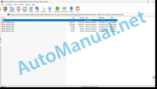
00 1400 639 3.pdf
00 1401 055 2.pdf
00 1402 656 2.pdf
00 1402 657 1.pdf
00 1402 803 1.pdf
00 1400 639 3.pdf:
COPILOT S7 GPS
1. Introduction
1.1 General information
1.1.1 Validity of the manual
1.1.2 Information about this instruction manual
1.1.3 Symbols and indications
1.1.4 Optional equipment
1.1.5 Qualified specialized workshop
1.1.6 Maintenance instructions
1.1.7 Information regarding warranty
1.1.8 Spare parts and technical questions
1.2 Proper application of the machine
1.2.1 Suitable GPS COPILOT application
1.2.2 Logically foreseeable erroneous application GPS COPILOT
2 Security
2.1 Recognize warning signs
2.1.1 Danger symbols
2.1.2 Keyword
2.2 Safety instructions
2.2.1 Importance of the instruction manual
2.2.2 Terminal software update
2.2.3 Observe graphic danger symbols and warning instructions
2.2.4 Requirements for all people who work with the product
2.2.5 Construction modifications
2.2.6 Optional equipment and spare parts
2.2.7 Using USB devices
2.2.8 Operation only in accordance with statutory commissioning
2.2.9 Technical status
2.2.10 Dangers when driving on the road and on terrain
Road traffic
Field trip
2.2.11 Electrical shock from electrical equipment
2.2.12 Maintenance work and repair work
3 Product Description
3.1 Summary and operation
3.1.1 COPILOT GPS Summary
3.1.2 S7 terminal overview
3.1.3 Summary corrective signals
EGNOS / WAAS / MSAS
3.1.4 Antenna summary
GNSS antenna
3.2 Optional equipment
3.2.1 GLONASS*
3.3 Identification plates and identification numbers
3.3.1 COPILOT S7 GPS identification plate
3.3.2 Terminal identification plate
4 Control and display instruments
4.1 S7 terminal overview
4.1.1 Button and prompt representation conventions
4.2 GPS COPILOT menu structure
4.2.1 Initial menu
4.2.2 Main menu, summary
4.2.3 Summary of DGPS visualizations
4.2.4 Menu
4.2.5 Menu
4.2.6 Menu
4.2.7 Menu
4.2.8 Menu
4.2.9 Menu
4.2.10 Menu
4.2.11 Menu
4.2.12 Menu
4.2.13
4.2.14 Menu
4.2.15 Menu
4.2.16 Menu
4.2.17 Menu
4.2.18 Menu
4.2.19 Menu
Menu
Menu
5 Technical data
5.1 GPS COPILOT
5.1.1 Corrective signal accuracy
5.1.2 COPILOT GPS Specification
5.2 S7 Terminal
5.2.1 Specification
6 Prepare the product
6.1 Turn off the machine and secure it
6.1.1 Turn off the machine and secure it
6.2 Perform before commissioning
6.2.1 Perform before the first commissioning of GPS COPILOT
6.2.2 Perform GPS COPILOT before each start-up
6.3 First start-up of the machine
6.3.1 Create vehicle profile
6.4 First start-up of the working device
6.4.1 Create device profile checklist
6.4.2 Create device profile
6.4.3 Select the type of coupling
6.4.4 Enter the measurements of the devices
Adjust the width of the device
Particularity in LEXION and TUCANO in MONTANA version
Adjust the overlap or gap
Working width
Adjust the movement of the device in the longitudinal direction
Adjust the movement of the device in the transverse direction
6.5 First start-up of the correction signal
6.5.1 First commissioning of the GNSS signal
6.5.2 Select the E-DIF correction type
6.5.3 Select the type of SBAS correction
6.6 Adjust subscriptions
6.6.1 Enter codes
7 Management
7.1 Checklists
7.1.1 Prepare field work
7.1.2 Carry out field work
7.2 GPS COPILOT
7.2.1 Turn on the terminal
Starting screen
7.2.2 Turn off the terminal
7.2.3 Manage control elements
Manage the keyboard
Operate the numeric keypad
Handle buttons with attached list
7.2.4 Direction direction indicator
7.2.5 GPS status
7.2.6 Connect USB data memory
7.3 GPS settings
7.3.1 Adjust BEIDOU
7.3.2 Adjust GNSS
7.3.3 Adjust NMEA broadcast
Limit NMEA broadcast to GPS signal
Record entries
Continue using the GNSS signal
7.3.4 Adjust E-DIF
Set reference point
Update reference point
7.3.5 Adjust SBAS
7.4 System settings
7.4.1 Adjust vision
Zoom in and out
Adjust the display mode
Adjust perspective
Hide buttons
View the buttons
7.4.2 Setting the language
7.4.3 Set units
7.4.4 Set the time
GMT Offset
7.4.5 Exchange control elements
7.4.6 Connect or disconnect the worked surface signal
7.4.7 Adjust day and night mode
7.4.8 Adjust screen brightness
7.4.9 Adjust the direction indicator
Sensitivity
7.4.10 Adjust the matrix
7.5 Vehicle settings
7.5.1 Load vehicle profile
7.5.2 Process vehicle profile
7.5.3 Export vehicle profiles
7.5.4 Import vehicle profiles
7.5.5 Delete vehicle profiles
7.6 Device settings
7.6.1 Load vehicle profile
7.6.2 Process device profile
7.6.3 Export device profiles
7.6.4 Import the device profile
7.6.5 Delete device profiles
7.7 Order processing
7.7.1 Create job
Create a new job from the initial menu
Create a new job from job management
7.7.2 Process notes
7.7.3 Load job
7.7.4 End the job
7.7.5 Continue the last used job
7.7.6 Export job
7.7.7 Import job
7.7.8 Delete job
7.7.9 Create template
7.7.10 Use model
7.7.11 Delete templates
7.8 Field trip with COPILOT GPS
7.8.1 Summary of types of field trips
7.9 Boundaries and markers
7.9.1 Use a surface counter
Record the parcel boundary
Interrupt recording
Plot boundary as a reference footprint
7.9.2 Set marker
User-defined bookmarks
Set user-defined bookmarks
7.9.3 Drive to markers
Select bookmark
Drive to bookmarks
7.10 Straight line guide
7.10.1 Straight line guide
7.10.2 Create reference fingerprint
7.10.3 Fix point B again
7.10.4 Straight line guide with angle (angle A=B)
7.10.5 Work the plot
Commutation
7.10.6 Load lines A=B
7.10.7 Process the naming of a line A=B
7.10.8 Move line A=B
7.11 Guide by circular lines
7.11.1 Guide service through circular lines
7.11.2 Create reference footprint
7.11.3 Work the plot
7.11.4 Load the circular footprint
7.11.5 Move the circular footprint
7.12 Guidance by contour lines
7.12.1 Using contour line guidance
7.12.2 Record reference fingerprint
Record new reference fingerprint
7.12.3 Work the plot
Commutation
Padlock function
7.13 Display of partial widths
7.13.1 Activate and deactivate the display of partial widths
7.13.2 Adjust the display of partial widths
Enter the number of partial widths of the attached device
Adjust the width of the individual sections of the attached device
Adjust the allowed overlap
Set the connection time
Set the shutdown time
7.13.3 Using the display of partial widths
8 Incident and solution
8.1 Errors and measures to take
8.1.1 Starting the COPILOT GPS system
8.1.2 Defective GNSS signal
8.1.3 EGNOS/WAAS/MSAS corrective signal
8.1.4 Error in footprint guidance
8.2 S7 Terminal
8.2.1 Take screenshots
8.3 Diagnosis
8.3.1 GPS-Setup
8.3.2 GPS Status
8.3.3 E-DIF Status
9 Maintenance
9.1 Summary of maintenance intervals
9.1.1 Every 100 hours of service or monthly
10 Decommissioning and waste disposal
10.1 General information
10.1.1 Decommissioning and waste disposal
11 EC declaration of conformity
11.1 GPS COPILOT
11.1.1 EC declaration of conformity
12 Technical dictionary and abbreviations
12.1 GPS COPILOT
12.1.1 Abbreviations
12.1.2 Units
00 1401 055 2.pdf:
GPS PILOT
1 Regarding this instruction manual
1.1 General data
1.1.1 Manual handling
1.1.2 Validity of instructions
1.1.3 Technical data
1.1.4 Road traffic permit
2 Security
2.1 General data
2.1.1 Read and observe the safety measures
2.1.2 To take special account
2.1.3 Proper machine application
2.2 Safety measures in this manual
2.2.1 Identification of warning and danger statements
3 Machine Description
3.1 Summary of correction signals
3.1.1 GPS PILOT EGNOS
3.1.2 GPS PILOT e-Dif
3.1.3 GPS PILOT OMNISTAR HP / XP
3.1.4 GPS PILOT BASELINE HD
3.1.5 GPS PILOT RTK
3.1.6 GPS PILOT RTK NET
3.2 Antenna summary
3.2.1 Antenna (EGNOS, e-Dif, BASELINE)
3.2.2 Antenna (BASELINE HD)
3.2.3 GPS antenna (OMNISTAR HP / XP, RTK ready, RTK, RTK NET)
3.2.4 Antenna (RTK)
3.2.5 Antenna (RTK NET)
CLAAS communication module (CCM) – connections
CLAAS Communication Module (CCM) – LED description
3.3 Terminal S3
3.3.1 Rear connections on terminal S3
3.3.2 Connections to the left of the S3 terminal
3.4 Navigation calculator (ECU)
3.4.1 Front side navigation calculator
3.4.2 Rear side navigation calculator
3.5 Valve unit
3.5.1 Valve control unit
3.5.2 Valve block
3.5.3 Locking block
3.5.4 Priority valve
3.5.5 Interchangeable shut-off valve
3.5.6 Wheel angle sensor
3.6 Steering wheel
3.6.1 Electric steering wheel
3.6.2 Control unit, steering wheel
3.7 Safety devices
3.7.1 Seat contact switch
3.7.2 Manual overexcitation
Hydraulic steering
electric steering wheel
3.7.3 Automatic shutdown / speed
3.8 Run switch
3.8.1 Standard main switch
3.8.2 Main switch in Challenger Auto-Guide
3.8.3 Main switch in FENDT Auto-Guide
3.8.4 Flywheel main switch
3.9 BASELINE HD base station
3.9.1 Base station
3.9.2 Charging device
3.9.3 Cable for external power supply
3.9.4 Cable for connection to PC
3.10 RTK fixed station
3.10.1 RTK Base Station
3.10.2 RTK broadcast antenna
4 Control and display instruments
4.1 General data
4.1.1 General warnings
4.1.2 Validity
4.2 S3 terminal summary
4.2.1 Button and prompt representation conventions
4.2.2 Connect the terminal
4.2.3 Turn off the terminal
4.2.4 Initial image
4.2.5 Summary menu
4.3 Main menu summary
4.3.1 Basic settings
4.3.2 GPS / settings
4.3.3 NMEA
4.3.4 GPS/radio-transmission
4.3.5 e-Diff
4.3.6 GPS / GPS details
4.3.7 Steering / Auto Settings
4.3.8 Address settings / details
4.3.9 Steering settings / settings
4.3.10 Steering settings / calibrate
Electric steering wheel variant
4.3.11 Address/status settings
4.3.12 Machine settings
4.3.13 Display of partial widths
4.3.14 Order processing
4.3.15 Field view
4.4 Address menu overview
4.4.1 Function buttons in the steering menu
5 Technical data
5.1 GPS PILOT
5.1.1 Correction signal accuracy
5.1.2 Power supply
5.1.3 Terminal S3
5.1.4 BASELINE
6 Preparation of the machine
6.1 General data
6.1.1 General warnings
6.2 Turn off the machine and secure it
6.2.1 Turn off the machine and secure it
6.3 Perform before commissioning
6.3.1 Perform before first start-up
6.3.2 Perform before each start-up
6.4 First start-up of the machine
6.4.1 General warnings
6.4.2 Open the calibration menu
6.4.3 Vehicle type and valve type calibration
Vehicle type
Valve type
Calibration set
6.4.4 Calibration of measurements
Longitudinal displacement of the antenna
Antenna height
Left/Right Antenna Shift
Distance between axis
6.4.5 ECU position calibration
6.4.6 Wheel angle sensor calibration
Left wheelbase
Right wheelbase
center wheelbase
6.4.7 Turn radius calibration
Left turning radius
Right turning radius
Maximum cornering speed
6.4.8 Valve current calibration
6.4.9 Calibration of the fine adjustment of the wheel angle sensor
Create line A=B
Follow the line A=B
6.4.10 Calibration of the electric steering wheel
Transmission of address
6.4.11 Lateral tilt calibration
Create line A=B
6.5 First start-up of the correction signal
6.5.1 EGNOS
6.5.2 OMNISTAR HP/XP
6.5.3 BASELINE HD
Settings in the terminal
Checklist for the first start-up of the base station
Prepare the charger
Charge the base station battery
Connect the base station
Power the base station with an external battery
Modify base station frequency
6.5.4 RTK
6.5.5 RTKNET
6.6 GPS PILOT
6.6.1 GPS PILOT
Start switch in field trip position
6.6.2 GPS status = “operational”
7 Management
7.1 General data
7.1.1 General warnings
7.2 BASELINE HD base station
7.2.1 Assemble the base ion
7.2.2 Connect the base station
7.3 Field trip with GPS PILOT
7.3.1 Order management
Create new job
7.3.2 Settings
Adjust the width of the device
Adjust overlap/gap
Adjust left/right scrolling
Adjust forward/backward shifting
7.3.3 Display of partial widths
Partial width display / CONEC preview
Display of partial widths / preview DESC
Display of partial widths / overlap
Display of partial widths / number of partial widths
Display of partial widths / width
Field path with partial width display
7.3.4 Summary of types of field trips
7.3.5 Use straight line guide
Create an A-B footprint
Set points A and B
Set points A and B and then learn point B again
Performing the following passes
Commutation
Pass numbering
Fix point A and learn the angle (angle AB)
Realization with several machines
Move lines A+B
Open the return points and go to them
7.3.6 Using contour line guidance
Performing the start step
Making a new start pass
Commutation
Padlock function
Surface counter
7.3.7 Using the A-B contour line guide
Performing the start step
Performing the following passes
7.3.8 Using circle line guidance
Performing the start step
7.3.9 Use e-Dif
Use for e-Dif work
7.3.10 Auto Spin
General instructions
Automatic spin calibration
Left turning radius
Right turning radius
Confirm turning radii
Duration menu activation
Driving speed adjustment
Next footprint setting
Representation of turning processes
Automatic turn input indication
Execution of a turning process
7.3.11 GPS PILOT / disconnection options
Activation button
Other disconnection conditions
8 Incident and solution
8.1 General data
8.1.1 General warnings
8.2 Errors and measures to take
8.2.1 Faulty first start-up (after installation)
8.2.2 Faulty system startup
8.2.3 Defective GPS
8.2.4 Defective EGNOS correction signal
8.2.5 Defective BASELINE HD correction signal
8.2.6 Defective OMNISTAR HP/XP correction signal
8.2.7 Defective RTK correction signal
8.2.8 Erroneous RTK NET correction signal
8.2.9 Error activating the automatic steering system
8.2.10 Error disabling auto steering
8.2.11 Error in footprint guidance
8.2.12 Distribution valve unit intermittent code error
9 Maintenance
9.1 General data
9.1.1 General warnings
9.2 Electrical/electronic installation
9.2.1 Battery
9.2.2 Removing/installing the base station battery
9.3 Maintenance instructions
9.3.1 Maintenance intervals
10 Service
10.1 General data
10.1.1 Spare parts and technical queries
11 Decommissioning and waste disposal
11.1 General data
11.1.1 Decommissioning and waste disposal
12 EU declaration of conformity
12.1 GPS PILOT – B82
12.1.1 EC declaration of conformity
13 Homologation
13.1 GPS PILOT – B82
13.1.1 Homologation
14 Technical dictionary and abbreviations
14.1 GPS PILOT
14.1.1 Abbreviations
00 1402 657 1.pdf:
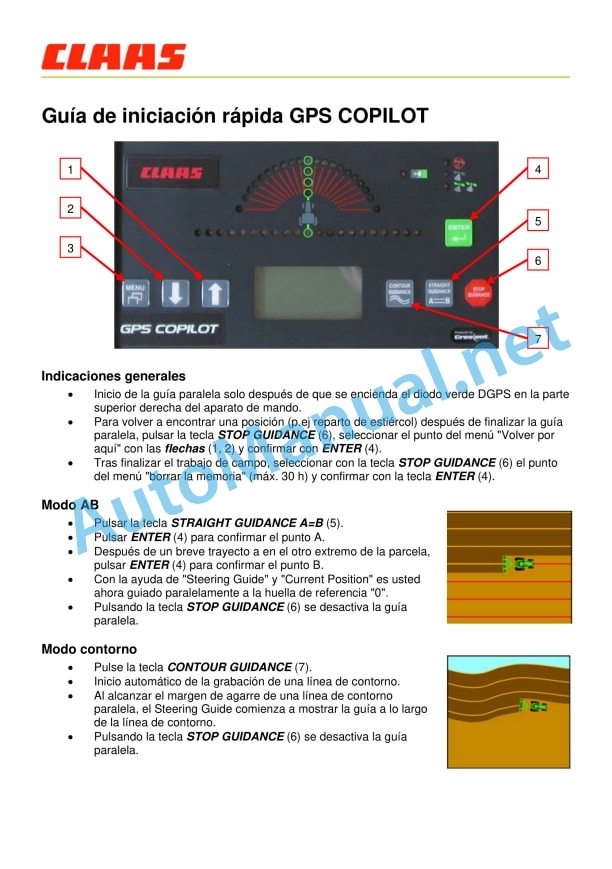
COPILOT GPS Quick Start Guide
General indications
Contour mode
Changing the working width
Change of signal type
Surface measurement
Automatic movement of lines A-B
John Deere Repair Technical Manual PDF
John Deere Repair Technical Manual PDF
John Deere Repair Technical Manual PDF
John Deere Repair Technical Manual PDF
John Deere Application List Component Technical Manual CTM106819 24AUG20
John Deere Parts Catalog PDF
John Deere Tractors 7500 Parts Catalog CPCQ26568 30 Jan 02 Portuguese
John Deere Repair Technical Manual PDF
John Deere Repair Technical Manual PDF
John Deere Repair Technical Manual PDF
John Deere DF Series 150 and 250 Transmissions (ANALOG) Component Technical Manual CTM147 05JUN98

