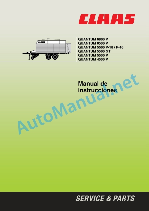
Claas Quantum 4500 P (696) Loader Wagons Operator Manual ES
$50.00
- Model: Quantum 4500 P (696) Loader Wagons
- Type Of Manual: Operator Manual
- Language: ES
- Format: PDF(s)
- Size: 14.3 MB
File List:
00 0188 848 7.pdf
00 0188 848 7.pdf:
1 Machine overview
2 Introduction
Introduction
Validity
4 Prologue
To observe in particular
Identification plate
Circulation on public roads
Circulation permit
Driving on public roads
License plate
Regular checks under art. 29 StVZO
5 Security measures
Use in accordance with the intended standards
Warning and danger signs
General safety and accident prevention rules
PTO shaft operation
Hydraulic system
Wheels/tyres, bolted joints
Maintenance
Noise level
Safety decals with warning symbols
6 Technical data
QUANTUM 6800P
QUANTUM 5500 P-18
QUANTUM 6500P
QUANTUM 5500 GT / 5500 P-16
QUANTUM 5500P
QUANTUM 4500P
7 Assembly
Mounting
QUANTUM 6800 P / 5500 P-18 up to machine number 615 0 2366
QUANTUM 6500 P (only for Spain)
QUANTUM 5500 P-16 / 5500 GT / 5500 P up to machine number 615 0 2366
QUANTUM 4500 P up to machine number 615 0 2366
QUANTUM 6800 P / 5500 P-18 from machine number 615 0 2367
QUANTUM 5500 P-16 / 5500 P from machine number 615 0 2367
Docking the machine for the first time
8 Before start-up
Check and observe before commissioning!
Hydraulic articulated lance
Shooting eyelets
Hydraulic articulated drawbar – Hitch coupling
Hitch coupling only – Spain
Lance height adjustment
Engage forced steering (additional equipment)
Adjust forced steering
Check/adjust hydraulic pressure
articulated axle
Articulated axle adaptation
Articulated shaft with CC clamping cone lock
Disengage
Electric system
Control panel
Driving lighting
ABS pneumatic brake system
ABS operation check
Hydraulic system
Open hydraulic system (standard system)
Closed hydraulic system
Take Power – beyond
Standard steering axle hydraulic connection (additional equipment)
Adjust the flow rate in the hydraulic system control block
Support leg
After coupling the self-loading trailer
Stopping the self-loading trailer
Pneumatic brake system
Double pipe system
Maneuvering tractor vehicles without a pneumatic brake system
Hydraulic brake
Parking break
Apply the brake
Release the brake
Access door
Disengage
Self-loading trailer with pneumatic brake system
Self-loading trailer with hydraulic brake
Self-loading trailer with ABS pneumatic brake system
Before transportation
Hydraulic drawbar suspension (additional equipment, only available ex factory)
Activate the drawbar damping
Road walking
9 Handling
Brief instructions
Discharge
articulated lance
Control witnesses
Two-phase motor (additional equipment)
Lower/raise the Pick-up
Preset the working height of the Pick-up
Roller tamper (QUANTUM 6800 P / 5500 P-18)
Retainer (QUANTUM 6500 P / 5500 P-16 / 5500 GT / 5500 P / 4500 P)
Open the knife box hydraulically
Connect the friction bottom – Fill the cargo space
Discharge
Open the tailgate
Empty the cargo compartment
Two-phase friction bottom motor
Close the tailgate
Cargo space lighting
Putting the self-loading trailer into service
General charging process
After use
Standard steering axle (Additional equipment, only available ex factory)
Standard steering axle lock
Standard steering axle release
Emergency management
Additional equipment
Tractor electrical system power supply
Control panel extension cable
Load-Sensing Hydraulic System Control Pipe
Lance extension for Hitch coupling (M01/0010)
Hydraulic connection for tractor (R03/0070)
Insert Fork Kit
10 Maintenance
Important maintenance instructions
Wheels/tyres
Brakes and axles
Air brakes
Hydraulic system
Lubrication
Protection devices
Brakes and axles
Pneumatic brake system
ABS pneumatic brake system
Bleed the pressurized air tank of water
Pipes air filter
Clean the filter element
Disassembled pipe air filter
Brake adjustment – Check brake cylinder piston stroke
Brake force regulator
brake linings
Forced direction
Fill/bleed forced direction
Bleed the steering cylinder
Bleed control cylinder
Adjust control cylinder stroke
Extend control cylinder
Pick up the control cylinder
Adjust the operating pressure of the forced steering
Cutting mechanism
Blade change
Disassembly of the blades
Blade assembly
Adjust the scraper box
main gear
Friction bottom gear
Friction bottom gear with two-phase motor
rotor gear
Retensioning of drive chains
Tension the Pick-up drive chain
Friction bottom chains
Air suspension
Lifting and lowering device for air suspension axles
Electric system
Adjusting Reed Switches
Hydraulic system
Change the pressure filter
pressure accumulator
Flexible hydraulic system pipes
Pressure gas spring
articulated axle
Pawl Clutch
Maintenance and lubrication openings
Protection devices
Screwed joints
Union elements
Conservation during winter
Lubricants table
11 Greasing scheme
Security measures
Lubricants
Lubrication
John Deere Repair Technical Manual PDF
John Deere Transmission Control Unit Component Technical Manual CTM157 15JUL05
John Deere Repair Technical Manual PDF
John Deere Repair Technical Manual PDF
John Deere Diesel Engines POWERTECH 2.9 L Component Technical Manual CTM126 Spanish
John Deere Parts Catalog PDF
John Deere Tractors 6300, 6500, and 6600 Parts Catalog CQ26564 (29SET05) Portuguese
John Deere Repair Technical Manual PDF
John Deere Repair Technical Manual PDF
John Deere 16, 18, 20 and 24HP Onan Engines Component Technical Manual CTM2 (19APR90)
John Deere Repair Technical Manual PDF
John Deere Repair Technical Manual PDF
John Deere Repair Technical Manual PDF


