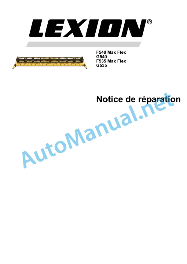
Claas F540-535 Maxflex G540-535 Cat (441) Combines Repair Manual FR
$300.00
- Model: F540-535 Maxflex G540-535 Cat (441) Combines
- Type Of Manual: Repair Manual
- Language: FR
- Format: PDF(s)
- Size: 15.3 MB
File List:
00 0295 576 0.pdf
00 0295 576 0.pdf:
Contents
1 CCN declarations
1.1 CCN (CLAAS Component Number)
1.1.1 General
1.1.2 Electrical standard
1.1.3 Hydraulic standard
1 Introduction
1.1 General advice
1.1.1 Use of the instructions
Texts and illustrations
Classification in module/group structure
Seek and find
Directions
1.1.2 Validity of the notice
1.2 General repair advice
1.2.1 Technical information
1.2.2 Origin of the failure
1.2.3 Spare parts
1.2.4 Diesel engine
1.2.5 Gearboxes
1.2.6 Alternator
1.2.7 Welds
1.2.8 Tensioning steel roller chains
1.2.9 Tapered annular fittings
1.2.10 Self-locking screws with micro-encapsulated glue
1.2.11 Liquid screw brake
1.2.12 Bearing with clamping ring
1.2.13 Clamping sleeve bearing
1.2.14 Screwed connections with cutting ring on hydraulic lines
1.2.15 Progressive ring fittings on hydraulic lines
1.2.16 Screwed connections with bicone ring on hydraulic lines
1.2.17 Hydraulic flexible lines
1.2.18 Tips for economical repair
1.3 Tightening torques
1.3.1 Tightening torque for metric adjustment thread
1.3.2 Tightening torques for fine metric threads
1.3.3 Tightening torques for hydraulic connections with cutting ring DIN 3861
1.3.4 Tightening torques for hydraulic connections and air conditioning connections with bicone ring and O-ring DIN 3865
1.3.5 Tightening torques for hydraulic threaded couplings DIN 3901
1.3.6 Tightening torques for hydraulic threaded sleeve, direction adjustable ISO 6149-2 / ISO 11926-2 (3)
1.3.7 Tightening torques for hydraulic swivel screw connections
1.3.8 Tightening torques for hollow screws DIN 7643
1.3.9 Tightening torques for brake line screw connections
1.3.10 Tightening torques for tangent screw clamps
1.3.11 Tightening torques for tires
1.4 Technical characteristics
1.4.1 Lubricants
2 Safety Tips
2.1 General advice
2.1.1 Important
2.1.2 Marking of warnings and dangers
2.1.3 General safety and accident prevention regulations
2.1.4 Front tools and trailer
2.1.5 Adjustment and maintenance work
2.1.6 Hydraulic fluid poses a risk of injury
2.1.7 First aid measures
3 Workouts
3.1 Drive belts / drive chains
3.1.1 General safety advice
3.1.2 Fixing material
3.1.3 Training scheme
3.1.4 Remove the belt (R1)
3.1.5 Remove the belt (R1)
3.1.6 Belt adjustment (R1)
3.1.7 Remove the chain (K6)
3.1.8 Install the chain (K6)
3.1.9 Adjust the chain (K6)
3.1.10 Remove the chain (K9)
3.1.11 Install the chain (K9)
3.1.12 Adjust the chain (K9)
3.2 Cardan shaft driving the front tool
3.2.1 Remove/disassemble the cardan shaft
3.2.2 Overview of the cardan shaft
3.2.3 Assemble/install the cardan shaft
3.2.4 Remove/disassemble the disengageable cam limiter
3.2.5 Overview of the disengageable cam limiter
3.2.6 Assemble/install the disengageable cam limiter
3.3 Intermediate shaft driving the front tool
3.3.1 Remove/disassemble the intermediate shaft
3.3.2 Overview of the intermediate shaft
3.3.3 Assemble/install the intermediate shaft
3.4 Knife drive
3.4.1 Overview of the driving pulley, belt (R1)
3.4.2 Remove the driving pulley, belt (R1)
3.4.3 Install the driving pulley, belt (R1)
3.4.4 Overview of the belt reversing pulley (R1)
3.4.5 Remove the reversing pulley, belt (R1)
3.4.6 Install the reversing pulley, belt (R1)
3.4.7 Overview of the belt tensioner pulley (R1)
3.4.8 Remove the tensioner roller, belt (R1)
3.4.9 Install the tensioner roller, belt (R1)
3.4.10 Overview of belt driven pulley (R1)
3.4.11 Remove the driven pulley, belt (R1)
3.4.12 Install the driven pulley, belt (R1)
3.4.13 Overview of planetary gears
3.4.14 Remove the planetary gear
3.4.15 Disassemble the planetary gear
3.4.16 Assemble the planetary gear
3.4.17 Install the planetary gear
3.5 Special blade drive tool
3.5.1 Remove the drive pulley, belt (R1)
3.5.2 Disassemble the planetary gear
3.5.3 Assemble the planetary gear
3.6 Feed screw drive
3.6.1 Remove the drive sprocket, chain (K6)
3.6.2 Install the drive sprocket, chain (K6)
3.6.3 Remove the output sprocket, chain (K6)
3.6.4 Install the output sprocket, chain (K6)
3.6.5 Remove the drive shaft
3.6.6 Install the drive shaft
3.6.7 Remove the outer feed screw bearing
3.6.8 Install the outer feed screw bearing
3.6.9 Remove/disassemble the inner feed screw bearing
3.6.10 Assemble/install the inner feed screw bearing
3.7 Special feed screw drive tool
3.7.1 Remove the drive sprocket, chain (K6)
3.7.2 Remove the outer feed screw bearing
3.8 Reel drive
3.8.1 Remove the drive sprocket, chain (K9)
3.8.2 Install the drive sprocket, chain (K9)
3.8.3 Remove the output sprocket, chain (K9)
3.8.4 Install the output sprocket, chain (K9)
3.8.5 Remove the false shaft on the left side of the left reel
3.8.6 Install the false shaft on the left side of the left reel
3.8.7 Remove the right side flange from the left reel
3.8.8 Install the flange on the right side of the left reel
3.8.9 Remove the false shaft on the right side of the right reel
3.8.10 Install the false shaft on the right side of the right reel
3.8.11 Remove the false shaft between the left side reel and the right side reel
3.8.12 Place the false shaft between the left side reel and the right side reel
4 Hydraulics
4.1 Valves / valves
4.1.1 Overview of solenoid valves
4.1.2 Remove the solenoid valves
4.1.3 Install the solenoid valves
4.1.4 Overview of check valves
4.1.5 Remove the check valves
4.1.6 Installation of non-return valves
4.2 Special tool, valves
4.2.1 Remove the solenoid valves
4.2.2 Installation of solenoid valves
4.3 Motors
4.3.1 Remove the hydraulic reel drive motor (2012)
4.3.2 Install the hydraulic reel drive motor (2012)
4.4 Cylinder
4.4.1 Remove the left side reel height adjustment hydraulic cylinder (3015)
4.4.2 Overview of the left-hand reel height adjustment hydraulic cylinder (3015)
4.4.3 Install the left side reel height adjustment hydraulic cylinder (3015)
4.4.4 Remove the central reel height adjustment hydraulic cylinder (3136)
4.4.5 Overview of the central reel height adjustment hydraulic cylinder (3136)
4.4.6 Installation of the central reel height adjustment hydraulic cylinder (3136)
4.4.7 Remove the right side reel height adjustment hydraulic cylinder (3014)
4.4.8 Overview of the right-hand reel height adjustment hydraulic cylinder (3014)
4.4.9 Installation of the hydraulic cylinder for adjusting the height of the reel on the right side (3014)
4.4.10 Remove the hydraulic cylinder for horizontal adjustment of the reel (3016)
4.4.11 Overview of the reel horizontal adjustment hydraulic cylinder (3016)
4.4.12 Installation of the hydraulic cylinder for horizontal adjustment of the reel (3016)
4.4.13 Overview of the cutting deck table locking hydraulic cylinder (3137)
5 Electrical/electronic system
5.1 Wiring harnesses/sensors
5.1.1 Sensor (B003) AUTO-CONTOUR left side feeler caliper, overview
5.1.2 Sensor (B004) AUTO-CONTOUR right side feeler bracket, overview
5.1.3 Reel height position sensor (B039), overview
6 Harvest feeding
6.1 Reel
6.1.1 Remove the left side reel
6.1.2 Install the left side reel
6.1.3 Remove the right side reel
6.1.4 Install the reel on the right side
6.1.5 Replacing the control rollers
6.1.6 Remove the control roller control
6.1.7 Install the control roller control
6.1.8 Remove the control star
6.1.9 Install the control star
6.1.10 Remove the reel star
6.1.11 Install the reel star
6.1.12 Remove the reel tine tube bearing
6.1.13 Install the reel tooth tube bearing
6.1.14 Remove the reel tine support tubes
6.1.15 Install the reel tine support tubes
6.1.16 Replace the reel fingers
6.1.17 Install the rivet nuts on the reel fingers
6.1.18 Remove the left side reel shaft bearing
6.1.19 Install the left side reel shaft bearing
6.1.20 Disassemble/remove the central reel shaft bearing
6.1.21 Assemble / install the reel shaft bearing in the center
6.1.22 Remove the right side reel shaft bearing
6.1.23 Install the right side reel shaft bearing
6.1.24 Remove the outer reel support arm
6.1.25 Install the outer reel support arm
6.1.26 Remove the reel support arm in the center
6.1.27 Place the reel support arm in the center
6.1.28 Replace the reel horizontal adjustment slide plates
7 Power group
7.1 Feed auger
7.1.1 Removing the feed auger
7.1.2 Install the feed screw
7.1.3 Remove the fingers from the feed screw
7.1.4 Install the feed screw finger
7.1.5 Remove the adjustment shaft
7.1.6 Install the adjustment shaft
7.1.7 Remove the control shaft
7.1.8 Install the control shaft
8 Cutting device
8.1 Cutting bar
8.1.1 Remove the knives
8.1.2 Place the knives
8.1.3 Adjust the blade clamps
Alphabetical index
John Deere Parts Catalog PDF
John Deere Harvesters 8500 and 8700 Parts Catalog CPCQ24910 Spanish
John Deere Repair Technical Manual PDF
John Deere Repair Technical Manual PDF
John Deere Diesel Engines PowerTech 4.5L and 6.8L – Motor Base Technical Manual 07MAY08 Portuguese
John Deere Repair Technical Manual PDF
John Deere Repair Technical Manual PDF
John Deere 16, 18, 20 and 24HP Onan Engines Component Technical Manual CTM2 (19APR90)
John Deere Repair Technical Manual PDF
John Deere Repair Technical Manual PDF
John Deere Diesel Engines POWERTECH 2.9 L Component Technical Manual CTM126 Spanish
John Deere Repair Technical Manual PDF
John Deere Application List Component Technical Manual CTM106819 24AUG20
John Deere Repair Technical Manual PDF


