Claas Jaguar 980-930 (494) Forage Harvesters Technical System FR
$300.00
- Model: Jaguar 980-930 (494) Forage Harvesters
- Type Of Manual: Technical System
- Language: FR
- Format: PDF(s)
- Size: 257 MB
File List:
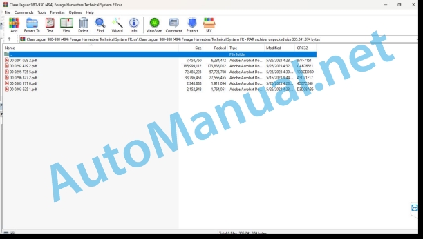
00 0291 028 2.pdf
00 0292 419 2.pdf
00 0295 735 5.pdf
00 0296 327 2.pdf
00 0303 171 0.pdf
00 0303 625 1.pdf
00 0291 028 2.pdf:
MB OM460LAMB OM502LAMB OM906LAMB OM926LA
Contents
CCN explanation
CCN (CLAAS Component Number – CLAAS part number)
Electrical standard
Overview
Hydraulic standard
Overview
CCN (CLAAS Component Number – CLAAS part number)
Introduction
Safety tips
Safety instructions and risk information
Validity of the notice
Validity of the notice
01 Motor
0125 Injection system, fuel supply
PLD Injection/Fuel System
PLD injection system
Function description
Plug-in pump power phases
Function description
Plug-in pump control
Function description
Classification of plug-in pumps
Example of plug-in pump nameplate
Coding, example of plug-in pump nameplate
Low fuel pressure measurement
Special tool
Preparing for low fuel pressure measurement
Function description
Measured values, low fuel pressure (after fuel filter)
0155 Engine controls
Diesel engine monitoring, diesel engine (MB TIER 3) TUCANO, JAGUAR
Measurement value table
Function description
Diesel engine monitoring, diesel engine (MB TIER 3) LEXION
Measurement value table
Function description
Diesel engine monitoring, diesel engine (MB TIER 4i) TUCANO, JAGUAR
Measurement value table
Function description
Torque limitation in case of urea shortage
Function description
Torque limitation in case of lack of urea quality
Function description
Torque limitation in case of time exceeded with system errors
Function description
Diesel engine monitoring, diesel engine (MB TIER 4i) LEXION
Measurement value table
Function description
Torque limitation in case of urea shortage
Function description
Torque limitation in case of lack of urea quality
Function description
Torque limitation in case of time exceeded with system errors
Function description
0165 Exhaust gas aftertreatment
MB TIER 4i compressed air system (LEXION, TUCANO)
Function description
Air dryer with integrated pressure regulator
Function description
Compressed air system MB TIER 4i (JAGUAR)
Function description
Air dryer with integrated pressure regulator
Function description
SCR system – Urea heating and injection
Function description
Combined filling level / urea temperature sensor
Function description
Urea pump unit
Function description
Reduction Catalyst Temperature Sensors
Function description
Dosing unit
Function description
NOx sensor
Function description
Combined sensor for intake air humidity and temperature
Function description
10 Electrical/electronic system
1012 Modules – Sensors
Module overview – MB (OM460LA, 502LA, 906LA, 926LA)
Designations
Module A015 – electronic engine management (ECM) – MB TIER 4i
Connector X1
Designations
Module allocation, connector X1
Connector X2, plug 1 of 2, inline 6 and V8 engine
Module allocation, connector X2 plug 1 of 2
Connector X2, plug 2 of 2, motor in line 6
Module allocation, connector X2 plug 2 of 2, motor in line 6
Connector X2, plug 2 of 2, V8 engine
Module allocation, connector X2, plug 2 of 2, V8 engine
Module A017 – Engine adaptation (ADM) – MB TIER 3
Designations
Designations
Module A017 – Engine adaptation (ADM) – MB TIER 4i
Designations
Designations
Module A032 – Reduction catalyst (SCR) – MB TIER4i
Designations
Designations
MB OM460LA sensors
Illustration of sensors
MB 502LA sensors
Illustration of sensors
MB sensors OM 906LA, OM 926LA
Illustration of sensors
1085 Network functions
BUS (CAN) system – Motor and machine
Function description
92 Diagnosis
Diagnosis according to error codes
9220 Diesel Engine Error Codes (J1939)
FMI (Failure Mode Indicator) error code
FMI (Failure Mode Indicator) error code
FMI 00 (Signal too large)
FMI 01 (signal too small)
IMF 02 (Implausible signal)
FMI 03 (voltage too high)
FMI 04 (voltage too low)
FMI 05 (current too low)
FMI 06 (current too high)
FMI 07 (mechanical error)
FMI 08 (frequency signal defective)
FMI 09 (communication error)
FMI 10 (signal modification too fast)
FMI 11 (multiple error)
FMI 12 (ECU faulty)
FMI 13 (signal outside calibration range)
FMI 16 (non-existent parameter)
FMI 17 (ECU not responding)
FMI 18 (voltage supply error)
FMI 19 (software conditions not met)
FMI 95 (no signal modification)
FMI 96 (CAN-bus system defective)
IMF 97 (implausible state)
IMF 98 (alarm)
IMF 99 (News)
Error Codes
J1939 Diesel Engine Error Code List (MB)
Function description
00 0295 735 5.pdf:
JAGUAR 980 – 930
Contents
CCN explanation
CCN (CLAAS Component Number)
Electrical standard
Summary table
Hydraulic standard
Overview
CCN (CLAAS Component Number)
Introduction
Validity of the notice
Summary table
01 Motor
0150 Engine assembly parts
Starting the diesel engine, adjusting the speed of the diesel engine (DAIMLER)
Measurement value table
Description of the function
Start diesel engine 1 and 2, diesel engine speed adjustment (DAIMLER)
Measurement value table
Description of the function
0155 Engine controls
Diesel engine monitoring, diesel engine (DAIMLER)
Measurement value table
Description of the function
Diesel engine monitoring, diesel engine 1 and 2 (DAIMLER)
Measurement value table
Description of the function
J1939 error code list / Engine diagnostics / Component position
03 Chassis
0315 Drive axle
Electro-hydraulic switching (EHS)
Measurement value table
Description of the function
0335 Advance command
Transmission
Measurement value table
Description of the function
High pressure sensor reference table (B097, B098)
0330 Rear wheel steering axle
4-Trac POWER TRAC system
Measurement value table
Description of the function
0365 Tire pressure adjustment system
Tire pressure regulation system
Measurement value table
Description of the function
Connection diagram
Designations
04 Brake
0405 Service brake
Service brake
Description of the function
Brake cylinder – service brake / parking brake
Designations
Description of the function
0415 Parking brake
Parking brake
Description of the function
Brake cylinder – service brake / parking brake
Designations
Description of the function
0420 Air trailer brake
Compressed air hitch brake system
Measurement value table
Description of the function
05 Management
0505 Steering
Steering system
Measurement value table
Description of the function
0510 Automatic steering
Autopilot / Sensor system
Measurement value table
Description of the function
Autopilot / Cam – Pilot
Measurement value table
Description of the function
Cam Settings – Pilot
Swath recognition Cam – Pilot
Conditions for optimal swath recognition
Maintenance Cam – Pilot
09 Hydraulic system
0905 Tank
Hydraulic oil tank
Designations
0910 Pumps
Variable displacement transmission pump
Designations
Hydraulic power drive
Designations
0915 Hydraulic circuit
Pressure filter
Designations
0920 Valves
Working hydraulic system distribution block module
Designations
Low pressure hydraulic system distribution block
Designations
Distribution block module raise – lower the front tool / electro-hydraulic control (EHS)
Designations
Pressure limiting distribution unit – AUTOCONTOUR corn spout
Designations
0925 Hydraulic motors
Variable displacement engine transmission
Designations
4-Trac module
Designations
0980 Hydraulic connection plan
Vehicle hydraulic system connection diagrams
0141 000 Hydraulic drive system, drive hydraulics, 4-Trac
Designations
0141 000.1 Hydraulic feed system, hydraulic feed system, 4-Trac (from machine No. …….)
Designations
0141 000.1 Hydraulic feed system, hydraulic feed system, 4-Trac (from machine no. …….) with diesel engine 1 and 2
Designations
0141 001 Working hydraulic system, steering hydraulic system, low pressure hydraulic system
Designations
0141 002 Raise/lower front implement, electro-hydraulic switching, hydraulic brake system
Designations
0143 830.0 Retrofit kit oil supply for molasses system
Designations
Hydraulic system connection diagrams of the front tool
ORBIS 750
ORBIS 900
Designations
Description of the function
Designations
10 Electrical/electronic system
1010 Central electrical system
Basic central electrical system
Fuse allocation
List of internal connections of the basic central electrical system (address identifier)
Central roof electrical system
Designations
Fuse allocation
Connection bay (slots)
Designations
1012 Modules – Sensors
Overview of modules
Part position modules
Designations
Module A006 – Automatic air conditioning (ACM)
Designations
Module A007 – cabin fan (CFC)
Designations
Module A009 – Autopilot (ATP)
Designations
Module A015 – electronic engine control (ECM) – Daimler
Designations
Module A017 – engine adaptation (ADM) – Daimler
Designations
Module A049 – Transmission (GDM) / Module A080 – Advance lever (GSL)
Designations
Module A069 – vehicle basic module (VBM- 1/3) – actoriel system
Designations
Module A069 – Vehicle Basic Module (VBM- 2/3) – Sensory system part 1
Designations
Module A069 – Vehicle Basic Module (VBM- 3/3) – Sensory system part 2
Designations
Module A075 – control panel (OPM)
Designations
Module A084 – bedknife adjustment (SBM)
Designations
Module A085 – tire pressure regulation (TPC)
Module A086 – throttle aperture adjustment (AGA)
Module A097 – corn front tool (MCU)
Module A105 – electronic engine control 2 (ECM-II) – Daimler
Designations
Module A106 – engine adaptation 2 (ADM-II) – Daimler
Designations
Module A125 – Dry matter measurement module (MMM)
1035 Multifunction use/control
Traveling on the road – switching travel in the field
T-signal
Measurement value table
Description of the function
1040 Performance measurement
Performance measurement
Measurement value table
Control and measure: conductance measurement / temperature measurement
1080 Electronic connections plan
Introduction connection diagrams
Overview of designations
CLAAS cable marking
Cable colors
Voltage supply
Actorial system
Sensory system
Actual value switch (edit = 0 or 1)
Internal connections
Overview of the CAN bus system
Communication
Standard
Electrical connection diagrams (SCM) to the machine No. 49402019
SCM 02 – Electrical voltage supply – start the diesel engine
Pluggable connectors
SCM 03 – Traveling on the road
Pluggable connectors
SCM 04 – Voltage supply of modules A003 – A049
Pluggable connectors
SCM 05 – Voltage supply of modules A069 – A076
Pluggable connectors
SCM 06 – Voltage supply of modules A080 – A125
Pluggable connectors
SCM 07 – Sensor voltage supply
Pluggable connectors
SCM 08 – Diesel engine speed adjustment, diesel engine monitoring
Pluggable connectors
SCM 09 – Vehicle CAN (CAN 0)
Pluggable connectors
SCM 10 – J1939-CAN (CAN 1) and CAN front tool (CAN 2)
Pluggable connectors
SCM 11 – Main Training
Pluggable connectors
SCM 12 – Diesel engine 2
Pluggable connectors
SCM 13 – Machine monitoring
Pluggable connectors
SCM 14 – Central lubrication
Pluggable connectors
SCM 15 – Transmission
Pluggable connectors
SCM 16 – Air conditioning
Pluggable connectors
SCM 17 – Raise – lower the front tool, transverse regulation
Pluggable connectors
SCM 18 – Additional distributor 1 – Fold the front tool
Pluggable connectors
SCM 19 – Front tool drive – Metal detector – Stone detector
Pluggable connectors
SCM 20 – Feed Drive Speed Change
Pluggable connectors
SCM 21 – Ejr elbow control
Pluggable connectors
SCM 22 – Corn Cracker
Pluggable connectors
SCM 23 – Direct Disc
Pluggable connectors
SCM 24 – Sharpening – counter-blade
Pluggable connectors
SCM 25 – Additional tow hook distributor – accelerator-opening adjustment
Pluggable connectors
SCM 26 – 4-Trac POWER TRAC system (all-wheel drive)
Pluggable connectors
SCM 27 – Brake circuit
Pluggable connectors
SCM 28 – Autopilot
Pluggable connectors
SCM 29 – Windshield wiper / washer
Pluggable connectors
SCM 30 – Flashing
Pluggable connectors
SCM 31 – Main lighting circuit – position lights
Pluggable connectors
SCM 32 – Low beam lights
Pluggable connectors
SCM 33ashboard lighting
Pluggable connectors
SCM 34 – Maintenance lighting
Pluggable connectors
SCM 35 – Sidefinder
Pluggable connectors
SCM 36 – Main work lighting circuit 1
Pluggable connectors
SCM 37 – Main work lighting circuit 2
Pluggable connectors
SCM 38 – Cabin equipment
Pluggable connectors
SCM 39 – Adjusting the mirrors
Pluggable connectors
SCM 40 – Service sockets
Pluggable connectors
SCM 41 – Tire pressure regulation
Pluggable connectors
SCM 42 – Silage additive device
Pluggable connectors
SCM 43 – Dry matter measurement
SCM 44 – Reserve (options)
Pluggable connectors
SCM 45 – Signal T (clocked signal)
Pluggable connectors
SCM 46 – Ground power supply
Pluggable connectors
SCM 47 – Overview of modules A003-A080
SCM 48 – Overview of modules A084-A125
Electrical system connection diagrams (SCM) from machine No. 49402020 / MTU – TIER 3 (R01- 2010)
SCM 02 – Electrical voltage supply – start the diesel engine
Pluggable connectors
SCM 06 – Voltage supply of modules A003 – A049
Pluggable connectors
SCM 07 – Voltage supply of modules A069 – A076
Pluggable connectors
SCM 08 – Voltage supply of modules A080 – A125
Pluggable connectors
SCM 09 – Sensor voltage supply
Pluggable connectors
SCM 10- Road travel
Pluggable connectors
SCM 11- Diesel engine speed adjustment, diesel engine monitoring
Pluggable connectors
SCM 12- Vehicle CAN (CAN 0)
Pluggable connectors
SCM 13 – J1939-CAN (CAN 1) and CAN front tool (CAN 2)
Pluggable connectors
SCM 14 – Main training
Pluggable connectors
SCM 15 – Diesel engine 2
Pluggable connectors
SCM 16 – Machine monitoring
Pluggable connectors
SCM 17 – Central lubrication
Pluggable connectors
SCM 18 – Transmission
Pluggable connectors
SCM 19 – Air conditioning
Pluggable connectors
SCM 20- Raise – lower the front tool, transverse regulation
Pluggable connectors
SCM 21- Additional distributor 1 – Fold the front tool
Pluggable connectors
SCM 22- Front tool drive – Metal detector – Stone detector
Pluggable connectors
SCM 23 – Feed Drive Speed Change
Pluggable connectors
SCM 24 – Ejector elbow control
Pluggable connectors
SCM 25 – Corn Cracker
Pluggable connectors
SCM 26 – Direct Disc
Pluggable connectors
SCM 27 – Sharpening – counter-blade
Pluggable connectors
SCM 28 – Additional towing hook distributor – accelerator-opening adjustment
Pluggable connectors
SCM 29 – 4-Trac POWER TRAC system (all-wheel drive)
Pluggable connectors
SCM 30- Brake circuit
Pluggable connectors
SCM 31- Autopilot
Pluggable connectors
SCM 32 – Windshiwiper/washer
Pluggable connectors
SCM 33 – Flashing
Pluggable connectors
SCM 34 – Main lighting circuit – position lights
Pluggable connectors
SCM 35 – Road lighting
Pluggable connectors
SCM 36 – Dashboard lighting
Pluggable connectors
SCM 37 – Maintenance lighting
Pluggable connectors
SCM 38 – Sidefinder
Pluggable connectors
SCM 39 – Main work lighting circuit 1
Pluggable connectors
SCM 40- Main work lighting circuit 2
Pluggable connectors
SCM 41- Cabin equipment
Pluggable connectors
SCM 42- Adjusting the mirrors
Pluggable connectors
SCM 43 – Service sockets
Pluggable connectors
SCM 44 – Tire pressure regulation
Pluggable connectors
SCM 45 – Silage additive device
Pluggable connectors
SCM 46 – Dry matter measurement / AUTO FILL
Pluggable connectors
SCM 47 – Reserve (options)
Pluggable connectors
SCM 48 – Signal T (clocked signal)
Pluggable connectors
SCM 49- Low beam lights France
Pluggable connectors
SCM 51- Ground power supply
Pluggable connectors
SCM 52- Overview of modules I. A003-A064
SCM 53- Overview of modules II. A049-A125
Connector database (chp CLAAS)
Example: representation of key numbers (CHP)
Key number (CHP)
1085 Network functions
Description of the function
12 Cabin – Driving position
1230 Headquarters
Seat contact
Measurement value table
1240 Air conditioning
Air conditioning automation
Measurement value table
Description of the function
Test menu:
Use test menu
20 Harvest feeding
2002 Front tool
Raise/lower the front tool
Measurement value table
Description of the function
Distribution block module raising – lowering of the front tool / electro-hydraulic control (EHS)
Connection diagram
Load maintaining valves
Pressure ranges
Piloted distributor
Measuring points
Fold/unfold the front tool (ORBIS)
Measurement value table
Description of the function
Pick-up / roller equalizer, support wheels
Measurement value table
Description of the function
Traveling on the road with a supporting wheel trailer
Measurement value table
Description of the function
Traveling on the road without a support wheel trailer (active oscillation damping)
Measurement value table
Description of the function
Restricted forward speed with too high axle load
21 Power group
2105 Feed cover
Hydraulic power
Measurement value table
Description of the function
Distribution block rapid power stop, blade drum brake
Designations
Metal detector
Stone detector
Stone detector error – CEBIS symbol
Feed drive speed change
Mounting the box (gear change feed drive)
Description of the function
Check and measure – hydraulic power supply
Check and measure: main drive brake valve function (brake the blade drum)
Control and measure: quick power off function
Check and measure: cutting length adjustment
a) Jaguar 980-950 / blade drum V12 (12/24) / feed gearbox 1st gear / large unit
b) Jaguar 980-950 / blade drum V12 (12/24) / feed gearbox 2nd gear / large unit
c) Jaguar 980-950 / blade drum V18 (18/36) / 1st gear power gearbox / large unit
d) Jaguar 980-950 / blade drum V18 (18/36) / 2nd gear power gearbox / large unit
e) Jaguar 940-930 / V12 blade drum (12/24) / 1st gear feed gearbox / small unit (Jaguar 930 – 940 up to No. 1278)
f) Jaguar 940-930 / V12 blade drum (12/24) / 2nd gear feed gearbox / small unit (Jaguar 930 – 940 up to No. 1278)
g) Jaguar 940-930 / blade drum V18 (18/36) / 1st gear feed gearbox / small unit (Jaguar 930 – 940 up to No. 1278)
h) Jaguar 940-930 / blade drum V18 (18/36) / 2nd gear feed gearbox / small unit (Jaguar 930 – 940 up to No. 1278)
Check and measure: metal detector function
Check and measure: stone detector function
Stone detector error – CEBIS symbol
Operating conditions of the supply hydraulics
a) Braked blade drum
Description of the function
b) ON main drive, blade drum not braked
Description of the function
c) Reverse
Description of the function
d) STOP of the hydraulic feed drive (transfer situation)
Description of the function
e) STOP of the hydraulic feed drive
Description of the function
Description of the function
g) Quick stop (transition situation)
Description of the function
h) Quick shutdown (power off)
Description of the function
26 Ground guidance
2605 Self-Contour
Measurement value table
Description of the function
AUTOCONTOUR (CAC) / manual transverse regulation
Measurement value table
Description of the function
4415 Counterblade
Counterblade (adjustment)
Measurement value table
Description of the function
Notes on adjusting the bedknife
4420 Blade holder drum
Chopper group (main drive)
Measurement value table
Description of the function
Designations
Control and measure – Main training
a) Main drive ON function
b) Function to brake the blade holder drum
Test evaluation – braking the blade drum:
4425 Knife sharpening device
Sharpen the blade drum
Measurement value table
Sharpening process
Designations
Description of the function
62 Discharge
6205 Corn cracker
Corn Cracker
Measurement value table
Hydraulic system of the Corn-Cracker
Air adjustment and bleeding
6215 Discharge chute
Adjusting the opening of the ejection accelerator – Validity: version without calibration key (S270)
Measurement value table
Description of the function
Adjusting the opening of the ejection accelerator – Validity: version with calibration button (S270)
Measurement value table
Description of the function
Rating (X) ejection accelerator
Clamping sleeve (1), lock nut (2)
S270 Calibration key throttle opening adjustment
6230 Ejector elbow
Ejector elbow
Measurement value table
Threshold values for the ejector elbow pilot calibration process – Validity: standard ejector elbow
Threshold values for the ejector elbow pilot calibration process – Validity: HD ejector elbow (reinforced version)
Description of the function
Ejector elbow start delay
Raising / Lowering the ejector elbow
Ejector elbow pilot
Monitoring of the ejector elbow position
6235 Preservative
Silage additive dosing device
Measurement value table
Description of the function
Silage additive – molasses system
Designations
Measurement value table
Description of the function
75 Central lubrication sys15 Pipes
Lubrication system
Measurement value table
Description of the function
Central lubrication system connection diagram
80 Assembly/body parts
8090 Accessories / Assembly set
D according to error codes
FMI (Failure Mode Indicator) error code
FMI (Failure Mode Indicator) error code
FMI 00 (signal too high)
FMI 01 (signal too small)
IMF 02 (implausible signal)
FMI 03 (voltage too high)
FMI 04 (voltage too low)
FMI 05 (current too low)
FMI 06 (current too high)
FMI 07 (mechanical error)
FMI 08 (incorrect frequency signal)
FMI 09 (communication error)
FMI 10 (signal modification too fast)
FMI 11 (multiple errors)
FMI 12 (ECU faulty)
FMI 13 (signal outside calibration range)
FMI 16 (non-existent parameter)
FMI 17 (ECU not responding)
FMI 18 (voltage supply error)
FMI 19 (software conditions not met)
FMI 95 (no signal modification)
FMI 96 (Faulty CAN bus system)
IMF 97 (implausible state)
IMF 98 (warning)
IMF 99 (News)
Error codes
JAGUAR error codes (type 494)
DTC (Diagnostic Trouble Code), overview
Location of parts
Electrical system
A Terminal / Modules
Sensors B
C electrical/electronic devices
D Light diode
Lighting E
G Voltage sources
H Signal device / indicator lights
K Relays
M Motor (electric)
R Potentiometer / resistor
S Switch / button – cabin control
Switch T – terminal control
Switch U – external control
V Electronic components
X Connectors
Y Electromagnetic coil
Z Actual value switch
Power Points 30
Grounding points 31_1 – 31_10
Hydraulic system
1001-1999 Oil tank/filter/oil cooler
2001-2999 Pump / Motor
3001-3999 Hydraulic cylinder
5001- 5999 Pressure accumulator
6001- 6999 Mechanically operated valve
7001- 7999 Hydraulically operated valve
9001- 9999 Measuring points / display instruments
00 0296 327 2.pdf:
MAN D2868MAN D2862
Contents
CCN explanation
CCN (CLAAS Component Number – CLAAS part number)
CCN (CLAAS Component Number – CLAAS part number)
Introduction
Safety tips
Safety instructions and dangers
Validity of the notice
Validity of the notice
01 Motor
0125 Injection system, fuel supply
System Description
Schematic structure of the Common Rail system
High pressure pump
High pressure pump CP3.4 / CP3.4+
ZME Measuring Unit (MProp Fuel Proportional Valve) (Y332-MAN, Y356-MAN)
Connector allocation
High pressure accumulator (Rail)
Pressure limiter
Rail Pressure Sensor (B487-MAN, B514-MAN)
Sensor characteristic curve
Connector allocation
Injector (Y341-MAN, Y350-MAN)
Fuel Temperature Sensor (B197-MAN)
Connector allocation
Connection diagram
0140 Exhaust device
Exhaust Gas Temperature Sensor (B633-MAN)
Connector allocation
0155 Engine controls
EDC7 control unit (A435-MAN, A570-MAN)
EDC7 C32 Master CE Level IIIB/Tier 4i V8 Control Unit (A435-MAN) Motor Connector Pin Allocation A
EDC7 C32 Master CE Level IIIB/Tier 4i V8 Control Unit (A435-MAN) Vehicle Connector Pin Allocation B
EDC7 C32 Master CE Level IIIB/Tier 4i V8 Control Unit (A435-MAN) Injector Connector Pin Allocation C
EDC7 C32 Slave CE Level IIIB/Tier 4i V8 Control Unit (A570-MAN) Motor A Connector Pin Allocation
EDC7 C32 Slave CE Level IIIB/Tier 4i V8 Control Unit (A570-MAN) Vehicle B Connector Pin Allocation
EDC7 C32 Slave CE Level IIIB/Tier 4i V8 Control Unit (A570-MAN) Injector Connector Pin Allocation C
Crankshaft RPM Sensor (Incremental RPM Sensor) (B488-MAN)
Connector allocation
Connection diagram
Camshaft RPM Sensor (Rpm Segmentation Sensor) (B489-MAN)
Connector allocation
Connection diagram
Oil Pressure Sensor (B104-MAN)
Sensor characteristic curve
Connector allocation
Fuel Pressure Sensor (B377-MAN)
Sensor characteristic curve
Connector allocation
Bosch LDF 6T Intake Pressure Sensor (B623-MAN)
Connector allocation
Coolant Temperature Sensor (B124-MAN)
Connector allocation
Connection diagram
10 Electrical/electronic system
1080 Electrical connection plan
Quick view EDC7 (D2862-V12)
Quick view EDC7 (V8)
Quick view EDC7 (R6)
Quick overview of the DCU15 power module (V-motors)
Quick overview of the DCU15 power module (in-line motor)
90 Others
9090 Diagnosis
System structure of K cables, diagnostic sockets
Diagnostic socket (X200-MAN)
HD-OBD diagnostic socket (X200-MAN)
Error logging
CDS error display
FMI (Failure Mode Identification)
EDC 7 SPN List (C32)
List of EDC7 C32 check steps (6-cylinder engine)
Check step list EDC7 C32 CE level IIIB/Tier 4i (6-cylinder engine)
1. Measurements on the EDC7 C32 engine management device
Check Step List EDC7 C32 Master-Slave CE Level IIIB/Tier 4i (8-Cylinder V-Engine)
1. Measurements on the EDC7 C32 engine management device
Hydraulic Checklist
Fundamentals of Error Detection
Catalog of questions in case of problems
Common errors and tips for solving them
General notes on troubleshooting in the fuel industry
Troubleshooting the low pressure system
Troubleshooting the high pressure system
Check leak volume
Measurement of overall leak volume
Preparations
Principle representation of the measurement structure
Checking the various injectors for leaks
High pressure pump flow measurement
Troubleshooting with CDS
Compression test
Acceleration test
Cylinder Disconnect Test
Acceleration test
General fuel diagram of CP3.4 D2868 oil lubricated high pressure pump
CP3.4 D2862 Oil Lubricated High Pressure Pump Fuel Schematic
D2868 Euro 4/5 engine fuel diagram
D2862 Euro 4/5 engine fuel diagram
Troubleshooting plan
Diagnostic program
SPN 94 FUEL SUPPLY PRESSURE
SPN 100 physical OIL PRESSURE
SPN 102 INTAKE PRESSURE AFTER RADIATOR (charge air pipe) physical
SPN 105 CHARGE AIR TEMPERATURE BEFORE CYLINDER INTAKE (after EGR) physical
SPN 108 physical ATMOSPHERIC PRESSURE
SPN 110 Physical COOLANT TEMPERATURE
SPN 168 BATTERY VOLTAGE
SPN 171 ROOM TEMPERATURE physical
SPN 173 EXHAUST GAS TEMPERATURE BEFORE PHYSICAL EXHAUST GAS AFTERTREATMENT
SPN 174 physical FUEL TEMPERATURE
SPN 190 ENGINE SPEED
Oscilloscope curves
SPN 609 CAN 1 MODULE
SPN 651 BANK 1 INJECTOR 1 (6-cylinder engine: cylinder 1; 8-cylinder engine master: Cylinder 1, slave: cylinder 5; 12-cylinder engine master: cylinder 1, slave: cylinder 12)
SPN 652 BANK 2 INJECTOR 1 (6-cylinder engine: cylinder 5; 8-cylinder engine master: Cylinder 2, slave: cylinder 7; 12-cylinder engine master: cylinder 2, slave: cylinder 11)
SPN 653 BANK 1 INJECTOR 2 (6-cylinder engine: cylinder 3; 8-cylinder engine master: Cylinder 3, slave: cylinder 6; 12-cylinder engine master: cylinder 3, slave: cylinder 10)
SPN 654 BANK 2 INJECTOR 2 (6-cylinder engine: cylinder 6; 8-cylinder engine master: Cylinder 4, slave: cylinder 8; 12-cylinder engine master: cylinder 6, slave: cylinder 7)
SPN 655 BANK 1 INJECTOR 3 (6-cylinder engine: cylinder 2; 12-cylinder engine master: Cylinder 5, slave: cylinder 8)
SPN 656 BANK 2 INJECTOR 3 (6-cylinder engine: cylinder 4; 12-cylinder engine master: Cylinder 4, slave: cylinder 9)
SPN 1079 RAIL PRESSURE SENSOR POWER SUPPLY
SPN 1080 POWER SUPPLY TO LOW FUEL PRESSURE SENSOR, INTAKE PRESSURE SENSOR, OIL PRESSURE SENSOR, EXHAUST GAS RELATIVE PRESSURE SENSOR
SPN 1131 CHARGE AIR TEMPERATURE AFTE
John Deere Parts Catalog PDF
John Deere Tractors 6300, 6500, and 6600 Parts Catalog CQ26564 (29SET05) Portuguese
John Deere Repair Technical Manual PDF
John Deere Repair Technical Manual PDF
John Deere Repair Technical Manual PDF
John Deere Diesel Engines PowerTech 4.5L and 6.8L – Motor Base Technical Manual 07MAY08 Portuguese
John Deere Repair Technical Manual PDF
John Deere Repair Technical Manual PDF
John Deere Repair Technical Manual PDF
John Deere POWERTECH E 4.5 and 6.8 L Diesel Engines TECHNICAL MANUAL 25JAN08
John Deere Repair Technical Manual PDF
John Deere Repair Technical Manual PDF
John Deere Repair Technical Manual PDF
John Deere DF Series 150 and 250 Transmissions (ANALOG) Component Technical Manual CTM147 05JUN98

