Claas Scorpion 732 (K31) Telehandlers Technical System FR
$300.00
- Model: Scorpion 732 (K31) Telehandlers
- Type Of Manual: Technical System
- Language: FR
- Format: PDF(s)
- Size: 244 MB
File List:
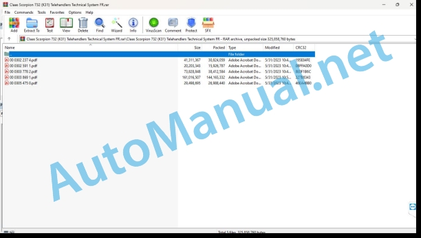
00 0302 237 4.pdf
00 0302 591 1.pdf
00 0303 778 2.pdf
00 0303 869 1.pdf
00 0305 475 0.pdf
00 0302 237 4.pdf:
SCORPION 1033 VARIPOWER (K34)SCORPION 741 VARIPOWER (K33)SCORPION 736 VARIPOWER (K32)SCORPION 732 VARIPOWER (K31)SCORPION 635 VARIPOWER (K30)
Contents
Introduction
Validity of the technical system instructions
Notes on the technical system instructions
Symbols and notes
Other remarks
Security
General informations
Marking of warnings and dangers
Safety Routines
First aid measures
Place the machine on jack stands
Place the machine on jack stands to carry out the transmission control report
Place the machine on jack stands for calibration of the DMS evaluation unit without crane installation
CCN explanation
CCN (CLAAS Component Number)
CLAAS electrical standard
Overview
CN standard for LIEBHERR Werke Telfs factories
Electronic designations of components (CN standard) from LIEBHERR Werke Telfs factories
Designation of hydraulic and mechanical components
CCN (CLAAS Component Number)
01 Motor
0135 Cooling system
Cooling system
Overview of the hydraulic system
Description of operation
Structure of the combined cooling system
Reversible fan
Overview of the hydraulic system
Description of operation
0150 Engine assembly parts
Start the diesel engine
0155 Engine controls
Diesel engine monitoring
0197 Test – Measurement – Adjustment
Checking and measuring the fan drive
Important notes on the inspection report
Required tools and screw connections
Preparations for drawing up the test report
Inspection and adjustment report
Preparation for hydraulic control
Execution
Fan drive pressure limitation
Measurement example, fan drive
03 Chassis
0305 Axle suspension
Level compensation – type K34
Neutral function of working hydraulics
Description of how level compensation, machine tilts to the right works
Description of how level compensation, machine tilts to the left works
0335 Advance command
Advancement training
Transmission function description
Regulation of the variable displacement pump with axial pistons
Variable displacement motor regulation
0397 Test – Measurement – Adjustment
Control and measure transmission
Important notes on the inspection report
Use of the test report
Required tools and screw connections
Preparations for drawing up the test report
Inspection and adjustment report
Preparation for hydraulic control
Tire check
Control with standard measuring devices
Operating temperature
Execution – charge pressure of the variable displacement pump
Check the charge pressure of the variable displacement pump
Measurement value table
Charge pressure
Example of measurement, charge pressure
Execution – Hydraulic zero position
Check the hydraulic zero position of the variable displacement pump
Hydraulic control
Hydraulic zero position
Example of measurement, hydraulic zero position
Running pressure limitation – check high pressure
Check high pressure
Prior check with CDS
High pressure pressure limitation
Example of measurement, forward high pressure test
Example of measurement, reverse high pressure test
Control with blind connection of the high pressure circuit
04 Brake
0405 Service brake
Service brake
Overview of the hydraulic brake system
Description of operation
0415 Parking brake
Parking brake
Designations
Overview of the hydraulic brake system
Description of operation
0420 Air trailer brake
Trailer air brake system (machine number range A)
Machine number range
Description of operation
Trailer air brake system (machine number range B)
Machine number range
Description of operation
Description of operation
0425 Hydraulic trailer brake
Hydraulic trailer brake, 1 line
Description of operation
Hydraulic trailer brake, 2 lines
Description of operation
0497 Test – Measurement – Adjustment
Check and measure the braking system
Important notes on the inspection report
Required tools and screw connections
Preparations for drawing up the test report
Inspection and adjustment report
Preparation for hydraulic control
Execution – Parking brake braking pressure
Check the brake hydraulics pilot pressure
Check the braking pressure of the parking brake
Measurement value table
Parking brake brake pressure – actuated
Execution – Brake pressure of service brake
Check the brake pressure of the service brake
Measurement value table
Service brake brake pressure
05 Management
0505 Steering
Steering system
Description of the operation of the steering system
Neutral function of steering hydraulics
Steering cylinder
Operation of management
Management body
0597 Check – Measure – Adjust
Check and measure the steering system
Important notes on the inspection report
Required tools and screw connections
Preparations for drawing up the test report
Inspection and adjustment report
Preparation for hydraulic control
Execution – Check the steering cylinder regulation pressure
Prior check with CDS
Measurement value table
Steering cylinder regulating pressure
06 Lifting device
0620 Telescopic arm
Raise/lower the telescopic boom
Function description “Raise/lower the telescopic boom”
Hydraulic system pilot control
Variable flow pump to proportional control block
Proportional control block
Hydraulic cylinder and compensation cylinder
Mount the telescopic boom
Lower the telescopiom
Retract/extract the telescopic boom
Neutral function of working hydraulics
Destion of the “Extract telescopic boom” function
Function description “Retract the telescopic boom”
Retract / extend the telescopic boom – Type K34
Neutral function of working hydraulics
Description of the “Extract telescopic boom” function
Function description “Retract the telescopic boom”
Cave/dump quick release plate
Neutral function of working hydraulics
Description of the “Quick cave/dump attachment plate” function
Caver quick release plate
Quick release plate
Bucket return
Description of operation
Dumping cylinder lock
Description of operation
Oscillation damping
Overview of the hydraulic oscillation damping system
Description of operation
Suspension of lifting device active
Automatic suspension of the lifting device
Suspension of lifting device disabled
0697 Test – Measuremenalibrate DMS evaluation electronics
0698 Fault / Remedy
Error detection by illuminated LEDs on lectronics
07 Hitch device
0720 Towing hook
Hitch hitch clevis
Overview of the hydraulic system
Description of operation Unlock Hitch hitch
Description of operation Lowering the Hitch hitch
Description of operation Mounting and locking the Hitch hitch
09 Hydraulic system
0900 Hydraulic system General
Neutral function of working hydraulics
Hydraulic system pilot control
Variable flow pump to proportional control block
Proportional control block
Hydraulic cylinder and compensation cylinder
Dumping cylinder
Telescopic cylinder
Control circuit
Constant service function of some parts
Primary protection pressure limiter (proportional control block)
Pilot order
Secondary protective pressure limiter
0905 Hydraulic oil tank
Hydraulic oil tank
Fittings
0910 Pumps
Variable displacement pump with axial pistons (advancement hydraulics)
Variable flow pump (working hydraulics)
Gear pump (charge pump)
0915 Hydraulic circuit
Hydraulic filter
Line filter
Fittings
Filter-sieve
0920 Valves
Proportional control block
Control lever
Parking brake valve block
Slow approach pedal
Rear axle adjustment valve
Steering mode control distributor
Management body
Blocking block
Fan proportional valve
Load Maintaining Valve (121-LWT)
Braked Down Valve (126-LWT)
Braked Down Valve (112-LWT)
Braked Down Valve (131-LWT)
Stop block (846-LWT) – type K34
Level compensation block (847-LWT) – type K34
0940 Power hydraulic system
3rd control circuit
Description of function of connection A on the 3rd control circuit
Description of function of connection B on the 3rd control circuit
Electrical switching of the 3rd control circuit
Hydraulic overview
Description of operation
External pressure relief of the 3rd control circuit
Overview of the hydraulic system for pressure relief of the 3rd control circuit
Description of operation
4th control circuit with tipper connection
Overview of the hydraulic system
Function description “Raise the tipper”
Description of the “Lower the tipper” function
4th control circuit with tipper hydraulics and rear hydraulics
Overview of the hydraulic system
Description of function “control of the 4th control circuit towards connection A with rear hydraulics”
Function description “control of the 4th control circuit towards connection B with rear hydraulics”
Function description “Raise the tipper”
Description of the function Lower the tipper
SCORPION quick fixing device
Overview of the hydraulic system
Description of operation
Couple and lock the work tool
Manitou quick release device
Overview of the hydraulic system
Description of operation
Coupltool
0980 Hydraulic connection plan
Connection diagrams – Types K30 and K31, (machine number range A)
MachineComplete hydraulic system
Advancement hydraulics
Steering hydraulics
Hydraulic braking
Cooling system
Working hydraulics
Dumping cylinder lock
3rd control circuit – pressure relief
Autohitch – automatic hitch
Suspension of the lifting device
Reversible fan
3rd control circuit – electrically switchable / pressure relief
SCORPION quick fixing device
MANITOU quick fixing device
4th control circuit – dumpster connection
4th control circuit – body and rear hydraulic system
4th control circuit – rear hydraulic system
Connection diagrams – Types K30 and K31, (machine number range B)
Machine number range
Complete hydraulic system I
Complete hydraulic system II
Advancement hydraulics
Steering hydraulics
Hydraulic braking
Working hydraulics
Cooling system
Cooling system, reversible fan
SCORPION quick fixing device
MANITOU quick fixing device
Hydraulic trailer brake
Hydraulic trailer brake, 1-line system
Lifting device suspension
Dumping cylinder lock
Autohitch, tipper and rear hydraulic system
Bucket return
3rd control circuit – pressure relief
3rd control circuit – electrically switchable / pressure relief
3rd control circuit, High Flow
4th control circuit – dumpster connection
4th control circuit – body and rear hydraulic system
4th control circuit – rear hydraulic system
5th control circuit
Connection diagrams – Types K32 and K33, (machine number range A)
Machine number range
Complete hydraulic system
Advancement hydraulics
Steering hydraulics
Hydraulic braking
Cooling system
Working hydraulics
Dumping cylinder lock
3rd control circuit – pressure relief
Hitch Hitch
Suspension of the lifting device
Reversible fan
3rd control circuit – electrically switchable / pressure relief
SCORPION quick fixing device
MANITOU quick fixing device
4th control circuit – dumpster connection
4th control circuit – body and rear hydraulic system
Connection diagrams – Types K32 and K33, (machine number range B)
Machine number range
Complete hydraulic system I
Complete hydraulic system II
Advancement hydraulics
Steering hydraulics
Hydraulic braking
Working hydraulics
Cooling system
Cooling system, reversible fan
SCORPION quick fixing device
MANITOU quick fixing device
Hydraulic trailer brake
Hydraulic trailer brake, 1-line system
Lifting device suspension
Dumping cylinder lock
Autohitch, tipper and rear hydraulic system
Bucket return
3rd control circuit – pressure relief
3rd control circuit – electrically switchable / pressure relief
3rd control circuit, High Flow
4th control circuit – dumpster connection
4th control circuit – body and rear hydraulic system
4th control circuit – rear hydraulic system
5th control circuit
Connection diagrams – Type K34, (machine number range A)
Machine number range
Complete hydraulic system
Advancement hydraulics
Steering hydraulics
Hydraulic braking
Cooling system
Working hydraulics
Dumping cylinder lock
3rd control circuit – pressure relief
Hitch Hitch
Suspension of the lifting device
Reversible fan
3rd control circuit – electrically switchable / pressure relief
SCORPION quick fixing device
MANITOU quick fixing device
4th control circuit – dumpster connection
4th control circuit – body and rear hydraulic system
Connection diagrams – Type K34, (machine number range B)
Machine number range
Complete hydraulic system I
Complete hydraulic system II
Advancement hydraulics
Steering hydraulics
Hydraulic braking
Working hydraulics
Cooling system
Cooling system, reversible fan
SCORPION quick fixing device
MANITOU quick fixing device
Hydraulic trailer brake
Hydraulic trailer brake, 1-line system
Lifting device suspension
Dumping cylinder lock
Autohitch, tipper and rear hydraulic system
Bucket return
3rd control circuit – pressure relief
3rd control circuit – electrically switchable / pressure relief
3rd control circuit, High Flow
4th control circuit – dumpster connection
4th control circuit – body and rear hydraulic system
4th control circuit – rear hydraulic system
5th control circuit
0997 Test – Measurement – Adjustment
Check and measure working hydraulics (machine number range A)
Machine number range
Important notes on the inspection report
Inspection and adjustment report
Preparation for hydraulic control
Control with standard measuring devices
Operating temperature
Differential pressure of working hydraulics
Execution – Check the reserve pressure of the working hydraulics
Measurement value table
Pressure always available from the working hydraulics
Pilot pressure of the working hydraulics
Pressure limitation of working hydraulics
Execution – Check the LS pressure relief valve control block
Measurement value table
Execution – Check the braked descent valve / safety valve with the hand pump
Check and measure working hydraulics machine number range B
Machine number range
Important notes on the inspection report
Inspection and adjustment report
Preparation for hydraulic control
Control with standard measuring devices
Operating temperature
Differential pressure of working hydraulics
Execution – Check the reserve pressure of the working hydraulics
Measurement value table
Pressure always available from the working hydraulics
Pilot pressure of the working hydraulics
Pressure limitation of working hydraulics
Execution – Check the LS pressure relief valve control block
Measurement value table
Execution – Check the braked descent valve / safety valve with the hand pump
10 Electrical/electronic system
1005 Power supply
Operation of the electrical battery cut-off switch
Description of the operation of the electronic battery cut-off switch
1010 Central electrical system
Central cabin electrical system
Central electrical system fuse allocation (cabin)
Fuse box in engine compartment
Equipment – fuse box in engine compartment
1012 Modules – Sensors
Module A1-LWT – Drive hydraulics control box
Designations
Connections without component designation
Module A4-LWT – DMS evaluation electronics
Designations
Connections without component designation
Module A30-LWT – Working hydraulics control box (1/2)
Designatns
Connections without component designation
Module A30-LWT – Working hydraulics control box (2/2)
Designations
Connectns without component designation
A33-LWT Module – Screen
Designations
Connections without component designation
A35-LWT module – LED display
Designations
Connections without component designation
Module A39-LWT – single lever
Designations
Connections without component designation
Module A36-LWT – diesel engine electronics (1/4)
Designations
Connections without component designation
Module A36-LWT – diesel engine electronics (2/4)
Designations
Connections without component designation
Module A36-LWT – diesel engine electronics (3/4)
Designations
Connections without component designation
Module A36-LWT – diesel engine electronics (4/4)
Designations
Module A36-LWT – diesel engine electronics (4/4)
Designations
Connections without component designation
A40-LWT module – control unit option pack 1
Designations
Connections without component designation
A50-LWT module – control unit option pack 2 (1/2)
Designations
Connections without component designation
A50-LWT module – control unit option pack 2 (2/2)
Designations
Connections without component designation
1080 Electronic connections plan
Electrical system connection diagrams (SCM) cable colors and linear representation
Introduction, electrical system connection diagrams (SCM) marking information
Electrical System Connection Diagrams (SCM) Base Machine
SCM 03 / Main fuse, power supply, automatic battery cut-off switch and ignition switch
Designations
Connectors
SCM 04 / Splice points and ground points
Designations
SCM 05 / Emergency stop, level 4 exhaust gas system/regeneration, EAT bypass and engine interface
Designations
Connectors
SCM 07 / torque limitation, pump control and supply of working hydraulics
Designations
Connectors
SCM 08 / Overload warning device and retarder
Designations
Connectors
SCM 09 / Control of the control block
Designations
Connectors
SCM 10 / Lift arm angle sensor, fan regulation and hydraulic oil temperature sensor
Designations
Connectors
SCM 12 / Forward hydraulics, drive pump, brake light and trailer brake
Designations
Connectors
SCM 13 / Axle proximity detector and steering mode adjustment
Designations
Connectors
SCM 14 / Steering mode valve control
Designations
Connectors
SCM 15 / Advance hydraulics, advance pedal angular sensors and manual slow approach
Designations
Connectors
SCM 16 / Parking brake, speed sensor, driver’s seat and engine start
Designations
Connectors
SCM 17 / Single lever
Designations
Connectors
SCM 18 / Display, tank sender, return filter pressure switch and brake compensator tank
Designations
Connectors
SCM 19 / Screen overview
Designations
SCM 20 / LED symbol display
Designations
Connectors
SCM 21 / Stepped switch for fan, fan motor and air conditioning
Designations
Connectors
SCM 22 / Windshield wiper, horn and steering column switch system
Designations
Connectors
SCM 23 / Lighting switching and door contactor
Designations
Connectors
SCM 24 / Exhaust gas system, power module and urea heater
Designations
Connectors
SCM 25 / Exhaust gas system, urea and ambient temperature sensor sensor system
Designations
Connectors
SCM 26 / Reversing warning system, steering column switch and lighting
Designations
Connectors
SCM 27 / Sockets and window heating
Designations
Connectors
SCM 28 / Work lights
Designations
Connectors
SCM 29 / Preparation of work light and trailer
Designations
Connectors
SCM 30 / Radio, immobilizer, camera system, license plate lighting and rotating beacon
Designations
Connectors
SCM 31 / Quick release device, fuel preheater, oil level sensor, central lubrication system, pneumatic system and TELEMATICS
Designations
Connectors
SCM 32 / Communication I
Designations
Connectors
SCM 33 / Communication II
Designations
Connectors
SCM 34 / Communication III (working hydraulics control)
Designations
Connectors
SCM 35 / Interface connector
Connectors
SCM 36 / Reserve main plate
Designations
Electrical system connection diagrams (SCM) diesel engine, TIER III
SCM 03 / Motor control device and motor sensory system
Designations
Modules, connections, ground points
SCM 04 / Engine interface – basic unit, power supply and fuel pump
Designations
Modules, connections, ground points
SCM 05 / Pressure switch and air conditioning
SCM 05 / Pressure switch and air conditioning
Designations
Modules, connections, ground points
Electrical System Connection Diagrams (SCM) Diesel Engine, Stage V
SCM 03 / Motor control device and motor sensory system
Designations
Modules, connections, ground points
SCM 04 / Exhaust gas system sensor system
Designations
Modules, connections, ground points
SCM 05 / Exhaust gas system relay
Designations
Modules, connections, ground points
SCM 06 / Engine interface – basic unit, power supply and fuel pump
Designations
Modules, connections, ground points
SCM 07 / Pressure switch and air conditioning
Designations
Modules, connections, ground points
Electrical System Connection Diagrams (SCM) Boom Wiring Harness
SCM 02 Arrow
Designations
Modules, connections, ground points
Electrical System Connection Diagrams (SCM) Option Pack 1
SCM 04 / Power supply for option pack 1 module
Designations
Connection plugs, ground points
SCM 05 / Tilting cylinder lock, level compensation
Designations
SCM 06 / Telescopic boom suspension
Designations
Connection plugs, ground points
SCM 07 / Automatic tipper feedback
Designations
Connection plugs, ground points
Electrical System Connection Diagrams (SCM) Option Pack 2
SCM 04 / Power supply for option pack 2 module
Designations
Connection plugs, ground points
SCM 05 / Reversible fan
Designations
Modules, connections, ground points
SCM 06 / Precise control of working hydraulics
Designations
SCM 07 / Automatic trailer coupling
Designations
Modules, connections, ground points
SCM 08 / Control of control circuits 4 and 5
Modules, connections, ground points
Electrical system connection diagrams (SCM) TELEMATICS
SCM 03 / TELEMATICS
Designations
Connectors
Immobilizer electrical system connection diagrams (SCM)
SCM 03 / Immobilizer
Designations
Connectors
Electrical System Connection Diagrams (SCM) Trailer Brake System
SCM 02 / Trailer braking system
Designations
Connectors
Electrical system connection diagrams (SCM) telescopic arm
SCM 03 / Telescopic arm
Designations
Connectors
Electrical System Connection Diagrams (SCM) Fuel Preheating
SCM 03 / Fuel preheating
Designations
Connectors
Electrical system connection diagrams (SCM) air pre-filtration
SCM 03 / Air pre-filtration
Designations
Connectors
SCM 04 / Air pre-filtration
Designations
Connectors
1081 Connector overview
Overview of connectors
1085 Network functions
Network CAN bus
Overview of CAN bus networks
Description of operation
12 Cabin – Driving position
1240 Air conditioning
Air conditioner
Structure
Dcription of operation
Air conditioner
Cooling system
75 Central lubrication system
7515 Pipes
Central lubrication system
Electric pump EP-1, mode of operation
Integrated electronic control S-EP 4
Explanation
Functional sequence
Process flow / timed control
Summary of signal displays
MX-F progressive distributor
Explanation
Description of operation
7597 Check – Measure – Adjust
Adjust – Central lubrication system
Setting parameters
Setting the operating pressure
92 Diagnosis
9210 Machine Error Codes
FMI Error Codes
FMI 00 (Signal too large)
FMI 01 (Signal too small)
IMF 02 (Implausible signal)
FMI 03 (voltage too high)
FMI 04 (voltage too low)
FMI 05 (current too low)
FMI 06 (current too high)
MI 07 (mechanical error)
FMI 08 (Faulty Frequency Signal)
FMI 09 (communication error)
FMI 10 (signal modification too fast)
FMI 11 (multiple errors)
FMI 12 (ECU faulty)
FMI 13 (signal outside calibrated range)
FMI 16 (non-existent parameter)
FMI 17 (ECU not responding)
FMI 18 (voltage supply error)
FMI 19 (software conditions not met)
FMI 95 (no signal modification)
FMI 96 (Faulty CAN bus system)
IMF 97 (implausible state)
IMF 98 (warning)
IMF 99 (News)
Machine error code list
Location of parts
Hydraulic system
Hydraulic components
Electrical system
A Modules, electronic components
B Sensors, signal transmitters
E Lighting
G Voltage sources
H Control lights
M Motor (electric)
R Potentiometer / Resistance
S Switch / Key
T Antennas
X Pluggable connectors
Y Electromagnetic coil
Ground points
00 0302 591 1.pdf:
SCORPION 1033 TREND (K34)SCORPION 741 TREND (K33)SCORPION 736 TREND (K32)SCORPION 732 TREND (K31)SCORPION 635 TREND (K30)
Contents
Introduction
Validity of the technical system instructions
Notes on the technical system instructions
Symbols and notes
Other remarks
Security
General instructions
Safety instructions
Technical system and other sources of information
Importance of Technical System
Staff qualification and organization
Requirements for all people who work with the machine
Changes to the machine
Constructive modifications
Additional equipment and spare parts
Requirements for spare parts
Workplace
Control when the machine is working
Technically impeccable condition
Technically impeccable condition of the machine
Dangers in case of damage to the machine
Respect the technical threshold values
Dangerous areas on the machine
Dangerous areas
Couple the machine to the work tool or trailer
Do not stand between the machine and the trailer
Risks when the drive is connected
Danger due to machine elements continuing to operate by inertia
Security devices
Maintain safety devices in operational capacity
Personal protective equipment
Personal protective equipment
Wear suitable clothing
Safety markings
Keep safety stickers clearly legible
Road safety
Risks when traveling on the road and in the fields
Tip-over risks
Prepare the machine for road travel
Park and store the machine safely
Unattended garage and storage
Remove foreign objects from the machine
Operating consumables
Unsuitable operating consumables
Safety in handling operating consumables and secondary consumables
Fuel is harmful to health
Refrigerants are harmful to health
Environmental protection and disposal
Chemical products
Never put chemicals in the cabin
Risks represented by the intervention environment
Fire hazards
Fatal electric shocks from overhead power lines
Behavior in the event of electrical discharges at overhead lines and in the event of lightning strikes
Sources of danger on the machine
Electrical discharge from the electrical system
Noise can harm your health
Vibrations can harm your health
Liquids under pressure
Pressurized air
Toxic exhaust gases
Hot surfaces
Dangers when ascending and descending
Safety when getting on and off
Risks when working on the machine
Work must only be carried out when the machine is stopped.
Inspection, adjustment, maintenance and repair work
Machine elements recorded and loads
Risks due to welding work
Risks due to painting work
Work on the electrical system
Work on the diesel engine
Fuel handling
Handling hot liquids
Marking of warnings and dangers
Safety Routines
First aid measures
Place the machine on jack stands
Place the machine on jack stands to carry out the transmission control report
Place the machine on jack stands for calibration of the DMS evaluation unit without crane installation
CCN explanation
CCN (CLAAS Component Number – CLAAS part number)
CCN (CLAAS Component Number)
LCN (LIEBHERR Component Number)
CLAAS electrical standard
Overview
CN standard for LIEBHERR Werke Telfs factories
Electronic designations of components (CN standard) from LIEBHERR Werke Telfs factories
Designation of hydraulic and mechanical components
CCN (CLAAS Component Number – CLAAS part number)
01 Motor
0135 Cooling system
Cooling system
Overview of the hydraulic system
Description of operation
Structure of the combined cooling system
Reversible fan
Overview of the hydraulic system
Description of operation
0150 Engine assembly parts
Start the diesel engine
0155 Engine controls
Diesel engine monitoring
0197 Control, measurement, adjustment
Checking and measuring the fan drive
Important notes on the inspection report
Required tools and screw connections
Preparations for drawing up the test report
Inspection and adjustment report
Preparation for hydraulic control
Execution
Fan drive control
Fan drive pressure limitation
03 Chassis
0305 Axle suspension
Level compensation – type K34
Neutral function of working hydraulics
Description of how level compensation, machine tilts to the right wor
John Deere Repair Technical Manual PDF
John Deere 16, 18, 20 and 24HP Onan Engines Component Technical Manual CTM2 (19APR90)
John Deere Repair Technical Manual PDF
John Deere Repair Technical Manual PDF
John Deere Repair Technical Manual PDF
John Deere 18-Speed PST Repair Manual Component Technical Manual CTM168 10DEC07
John Deere Repair Technical Manual PDF
John Deere Parts Catalog PDF
John Deere Harvesters 8500 and 8700 Parts Catalog CPCQ24910 Spanish
John Deere Repair Technical Manual PDF
John Deere Parts Catalog PDF
John Deere Tractors 6300, 6500, and 6600 Parts Catalog CQ26564 (29SET05) Portuguese
John Deere Repair Technical Manual PDF
John Deere Repair Technical Manual PDF
John Deere DF Series 150 and 250 Transmissions (ANALOG) Component Technical Manual CTM147 05JUN98

