- Claas
- Grove
- New Holland
- Komatsu
- Kubota
- John Deere
- Linde
- Bomag
- CASE
- Clark
- JCB
- Jungheinrich
- Linde
- Yale
- Yanmar
- Manitou
- Manitowoc
- CNH
- Doosan
- Fiatagri
- Fiatallis
- Fiatallis Other Manual PDF
- Flexi Coil
- Ford New Holland
- Ford New Holland Other Manual PDF
- Huyndai
- Hypac
- Hyster
- Hyster Service Manual PDF
- Isuzu
- Kobelco
- Kohler
- Krupp
- Lombardini
- Mahindra
- Nuvera
- Perkins
- Sperry New Holland
- Utilev
- Versatile
- ZF
New Holland T4.90 FB, T4.100 FB, T4.110 FB Trator Service Manual 51500239
$30.00
- Type Of Manual: Service Manual
- Manual ID: 51500239
- Format: PDF
- Size: 220.0MB
- Number of Pages: 1365
- Serial Number:
51500239
-
Model List:
- T4.90 FB
- T4.90 T4.100 FB
- T4.90 T4.110 FB Trator
- 1. SM T4 FB
- 1.1. INDEX
- 1.2. INTRODUCTION
- 1.2.1. Reading this manual
- 1.2.2. Safety rules
- 1.2.3. General
- 1.2.4. Technical characteristics
- 1.2.5. Tightening torques and sealants
- 1.2.6. General assembly instructions
- 1.3. ENGINE
- 1.3.1. Safety rules
- 1.3.2. General information
- 1.3.3. Maintenance
- 1.3.4. External views of engine
- 1.3.5. Engine oil
- 1.3.6. Coolant
- 1.3.7. Air filter
- 1.3.8. Injection system
- 1.3.9. Fuel filter
- 1.3.10. Alternator PolyV belt
- 1.3.11. Diesel particulate filter (DPF)
- 1.3.12. Diesel particulate filter (DPF)
- 1.3.13. Removal and installation
- 1.3.14. Tightening torques
- 1.3.15. Wiring harness connector kit
- 1.3.16. Timing side
- 1.3.17. Oil pump
- 1.3.18. Crankshaft gear
- 1.3.19. Hydraulic pump idler gear (between crankshaft and camshaft gears)
- 1.3.20. high pressure pump idler gear (between camshaft gear and injection pump gear)
- 1.3.21. Hydraulic pump gear
- 1.3.22. Idler pulley
- 1.3.23. Crankshaft hub and pulley
- 1.3.24. Water pump and pulley
- 1.3.25. Timing cover
- 1.3.26. Front oil seal
- 1.3.27. Turbocharger
- 1.3.28. EGR heat exchanger
- 1.3.29. Exhaust gas temperature and pressure sensors
- 1.3.30. Throttle valve
- 1.3.31. Exhaust manifold
- 1.3.32. Intake manifold
- 1.3.33. Crankshaft endfloat
- 1.3.34. Engine flywheel
- 1.3.35. Engine flywheel ring gear
- 1.3.36. Flywheel housing
- 1.3.37. Rear crankshaft bearing
- 1.3.38. Shim
- 1.3.39. Rear main bearing bush
- 1.3.40. Rear oil seal
- 1.3.41. Tone wheel
- 1.3.42. Head gasket Pistontohead clearance
- 1.3.43. Head single head for all cylinders
- 1.3.44. Retightening heads
- 1.3.45. Valve guides
- 1.3.46. Valve seat
- 1.3.47. Valves
- 1.3.48. Valve spring
- 1.3.49. Rockers
- 1.3.50. Hydraulic tappets
- 1.3.51. Rocker rods
- 1.3.52. Fracturesplit connecting rod
- 1.3.53. Piston
- 1.3.54. Engine oil sump and transmission pipe
- 1.3.55. Oil suction pipe
- 1.3.56. Engine oil pressure relief valve
- 1.3.57. Separator oil drain valve
- 1.3.58. Crankshaft balancer weights
- 1.3.59. Crankcase
- 1.3.60. Cylinder sleeve
- 1.3.61. Camshaft
- 1.3.62. Camshaft bushes
- 1.3.63. Front camshaft bush
- 1.3.64. Piston cooling oil jets
- 1.3.65. Crankshaft
- 1.3.66. Front crankshaft bush
- 1.3.67. Injection system
- 1.3.68. Low pressure injection system Specifications
- 1.3.69. High pressure pump
- 1.3.70. Injectors
- 1.3.71. Rail
- 1.3.72. High pressure injection system components Tightening procedure
- 1.3.73. Oil filter housing
- 1.3.74. Rocker cover
- 1.3.75. Thermostat valve
- 1.3.76. Alternator
- 1.3.77. Alternator pulley
- 1.3.78. Alternator regulator
- 1.3.79. Alternator bracket
- 1.3.80. Starter motor
- 1.3.81. Electric sensors
- 1.3.82. Special tools
- 1.4. CLUTCH HOUSING
- 1.4.1. Safety rules
- 1.4.2. General introduction
- 1.4.3. Technical characteristics
- 1.4.4. Disassembly
- 1.4.5. Main inspection, reassembly and adjustment procedures
- 1.4.6. Tightening torques
- 1.4.7. Tools necessary
- 1.5. GEARBOX
- 1.5.1. Safety rules
- 1.5.2. General introduction
- 1.5.3. Technical characteristics
- 1.5.4. Disassembly
- 1.5.5. Main inspection, reassembly and adjustment procedures
- 1.5.6. Tightening torques
- 1.5.7. Tools necessary
- 1.6. REAR DIFFERENTIAL
- 1.6.1. Safety rules
- 1.6.2. General introduction
- 1.6.3. Technical characteristics
- 1.6.4. Disassembly
- 1.6.5. Main inspection, reassembly and adjustment procedures
- 1.6.6. Tightening torques
- 1.6.7. Tools necessary
- 1.7. REAR FINAL DRIVE UNITS
- 1.7.1. Safety rules
- 1.7.2. General introduction
- 1.7.3. Disassembly
- 1.7.4. Main inspection, reassembly and adjustment procedures
- 1.7.5. Tightening torques
- 1.7.6. Tools necessary
- 1.8. FRONT AXLE
- 1.8.1. Safety rules
- 1.8.2. General introduction
- 1.8.3. Technical characteristics
- 1.8.4. Removal
- 1.8.5. Main components
- 1.8.6. Refitting
- 1.8.7. Tightening torques
- 1.8.8. Tools necessary
- 1.9. TRANSFER CASE
- 1.9.1. Safety rules
- 1.9.2. General introduction
- 1.9.3. Technical characteristics
- 1.9.4. Disassembly
- 1.9.5. Main inspection, reassembly and adjustment procedures
- 1.9.6. Tightening torques
- 1.9.7. Tools necessary
- 1.10. REAR POWER TAKE OFF
- 1.10.1. Safety rules
- 1.10.2. General introduction
- 1.10.3. Technical characteristics
- 1.10.4. Disassembly
- 1.10.5. Main inspection, reassembly and adjustment procedures
- 1.10.6. Tightening torques
- 1.10.7. Tools necessary
- 1.11. BRAKES
- 1.11.1. Safety rules
- 1.11.2. General introduction
- 1.11.3. Technical characteristics
- 1.11.4. Disassembly
- 1.11.5. Main inspection, reassembly and adjustment procedures
- 1.12. HYDRAULIC SYSTEM
- 1.12.1. Safety rules
- 1.12.2. Main hydraulic circuit
- 1.12.3. Lift hydraulic system
- 1.12.4. Lift with position and draft control
- 1.12.5. Main components
- 1.12.6. Checking operating pressure values
- 1.12.7. Tools necessary
- 1.13. PLATFORM
- 1.13.1. Safety rules
- 1.13.2. Removing and refitting the platform
- 1.13.3. Tools necessary
- 1.14.1. Safety rules
- 1.14.2. Technical characteristics
- 1.14.3. Removing and refitting
- 1.14.4. Air conditioning system
- 1.14.5. Tools necessary
- 1.15. REAR HITCH
- 1.15.1. Safety notes
- 1.15.2. Technical specifications
- 1.15.3. Disassembly
- 1.15.4. Main inspection, reassembly and adjustment operations
- 1.15.5. Tightening torques
- 1.15.6. Tools required
- 1.16. ELECTRICAL SYSTEM
- 1.16.1. Safety rules
- 1.16.2. Introduction
- 1.16.3. Wiring looms
- 1.16.4. Systems
- 1.16.5. Systems for wiring harnesses (from serial No. 0000622678 for Roll Bar versions with SG1/1GL11/1 cabs and front lift)
- 1.16.6. Fuse box
- 1.16.7. Error code list
- 1.16.8. Cable colour table
- 1.17. TROUBLESHOOTING
- 1.17.1. Engine control unit (ECU)
- 1.17.2. Vehicle control unit (VCU)
- 1.17.3. Connector List
- 1.18. SPECIAL TOOLS
- 1.18.1. Engine tools list
- 1.18.2. Vehicle tools list
New Holland Service Manual PDF
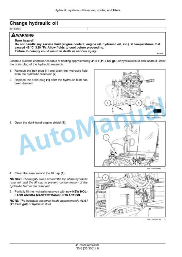
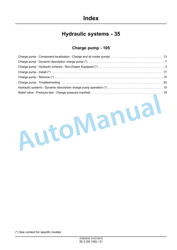
New Holland 130 Speedrower Tier 3 Self-Propelled Windrower Service Manual 47904535
New Holland Service Manual PDF
New Holland 100, 115, 135, 160 CV Tractor Repair Manual 6035432000 ITA
New Holland Service Manual PDF
New Holland 12.9L Turbo Compound Engine Repair Manual 87737594
New Holland Service Manual PDF
New Holland 130 Speedrower Self-Propelled Windrower Service Manual 47698328
New Holland Service Manual PDF
New Holland 100, 115, 135, 160 HP Tractor Repair Manual 6035432100
New Holland Service Manual PDF
New Holland 120, 125 Rustler Tractor Service Manual CLC103700628
- Claas
- Grove
- New Holland
- Komatsu
- Kubota
- John Deere
- Linde
- Bomag
- CASE
- Clark
- JCB
- Jungheinrich
- Linde
- Yale
- Yanmar
- Manitou
- Manitowoc
- CNH
- Doosan
- Fiatagri
- Fiatallis
- Fiatallis Other Manual PDF
- Flexi Coil
- Ford New Holland
- Ford New Holland Other Manual PDF
- Huyndai
- Hypac
- Hyster
- Hyster Service Manual PDF
- Isuzu
- Kobelco
- Kohler
- Krupp
- Lombardini
- Mahindra
- Nuvera
- Perkins
- Sperry New Holland
- Utilev
- Versatile
- ZF


