


New Holland Service Manual PDF
New Holland 102, 103, 105 StackCruiser Tier 4B Final Bale Wagon Service Manual 48190534
$30.00
New Holland Service Manual PDF
New Holland 130 Speedrower Self-Propelled Windrower Service Manual 47698328
$30.00
New Holland Service Manual PDF
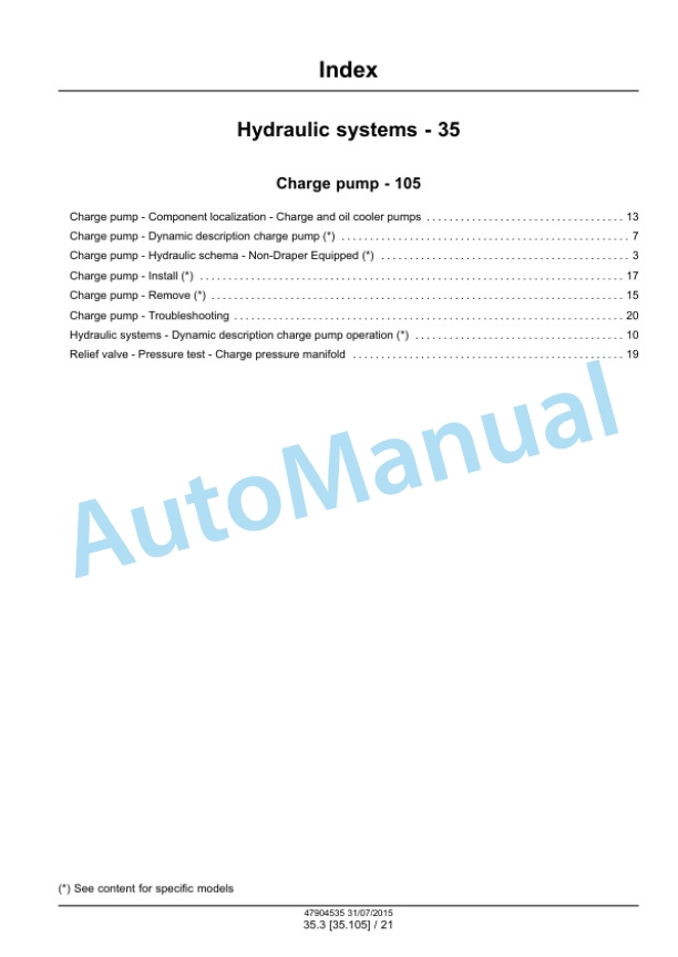
New Holland 130 Speedrower Tier 3 Self-Propelled Windrower Service Manual 47904535
$30.00
New Holland Service Manual PDF
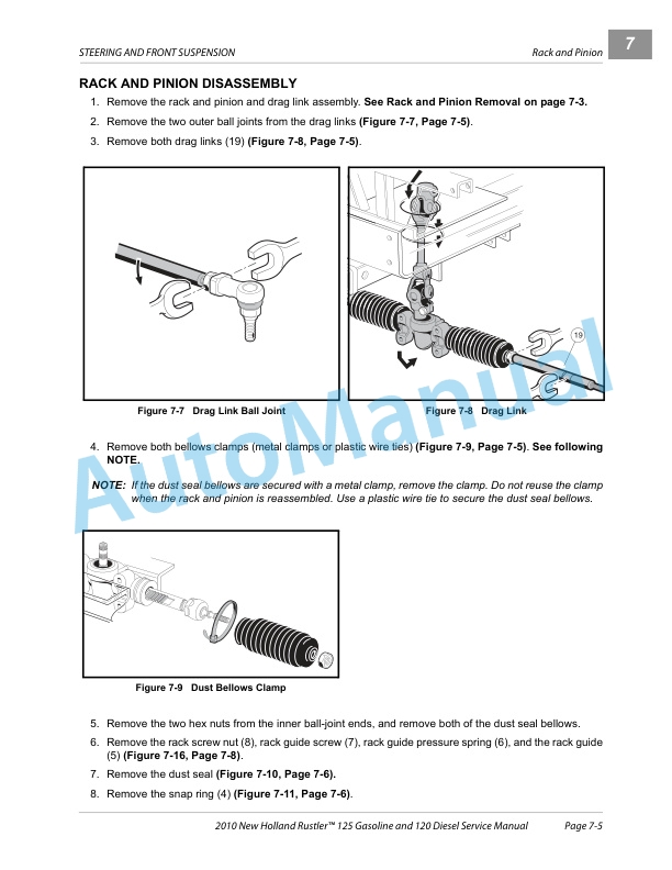
New Holland 120, 125 Rustler Tractor Service Manual CLC103700628
$30.00
New Holland Service Manual PDF
New Holland 1320, 1520, 1620, 1715, 1720 Tractor Service Manual 40132030
$30.00
New Holland Service Manual PDF
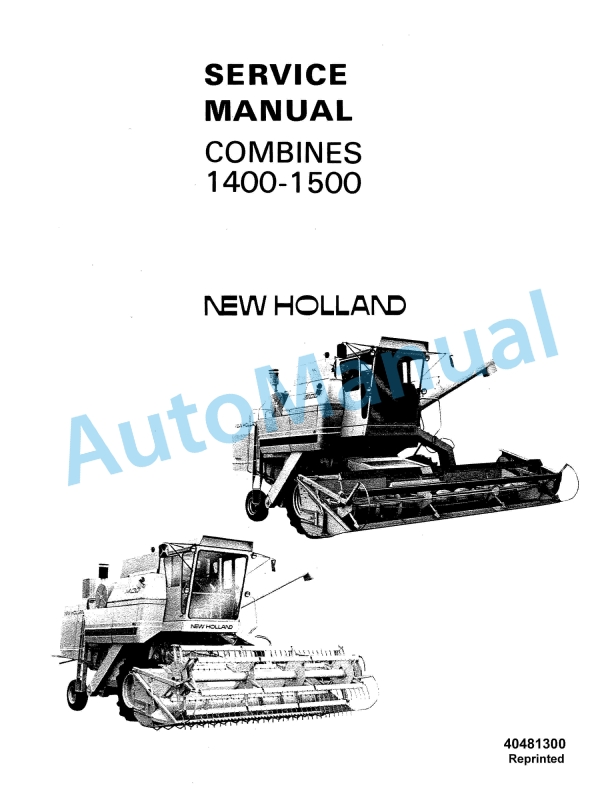
New Holland 1400, 1500 Combine Tractor Service Manual 40481300
$30.00
