No products in the cart.
Return to shop
$50.00
Komatsu Shop Manual PDF
Komatsu 108 Series Diesel Engine Shop Manual SEBE62210104
Komatsu 107E-1 Series Motor Shop Manual KPBM016106
Komatsu 107E-2 Series Engine Shop Manual SEN05623-09
Komatsu 102 Series Diesel Engine Shop Manual 6D102E-BE4
Komatsu 107E-1 Series Engine Shop Manual SEN00161-27
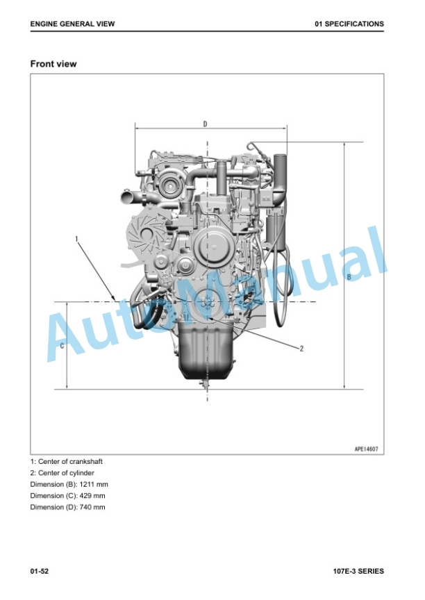
Komatsu 107E-3 Series Engine Shop Manual SEN06502-11
Komatsu 100, 125, TD-7, TD-8 Series C,E Loader Shop Manual ISS-1543
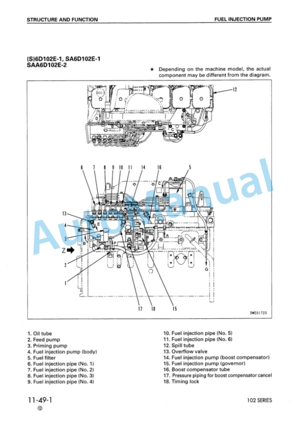
Komatsu 102 Series Diesel Engine Shop Manual SEBM010025
Komatsu 102 Series Diesel Engine Shop Manual SM140
Komatsu 108 Series Diesel Engine Shop Manual SEBE62210103


