Komatsu 82E-6, 98E-6 Series Diesel Engine Shop Manual SEN04211-03
$40.00
- Type Of Manual: Shop Manual
- Manual ID: SEN04211-03
- Format: PDF
- Size: 42.4MB
- Number of Pages: 385
Category: Komatsu Shop Manual PDF
-
Model List:
- 82E-6 Series Diesel Engine
- 98E-6 Series Diesel Engine
- 1. COVER
- 2. Index and foreword
- 2.1. Index
- 2.1.1. Composition of shop manual
- 2.1.2. Table of contents
- 2.2. Foreword and general information
- 2.2.1. Introduction
- 2.2.2. Applicable machine model and serial number
- 2.2.3. Safety Statements
- 2.2.4. Safety Precautions
- 3. Specification
- 3.1. Specification and technical data
- 3.1.1. Component identification
- 3.1.2. Function of major engine components
- 3.1.3. Main electronic control components and features
- 3.1.4. Function of cooling system components
- 3.1.5. Diesel fuel
- 3.1.6. Engine oil
- 3.1.7. Engine coolant
- 3.1.8. Specifications
- 3.1.9. Principal engine specifications
- 3.1.10. Engine service standards
- 3.1.11. Tightening torques for standard bolts and nuts
- 3.1.12. Abbreviations and symbols
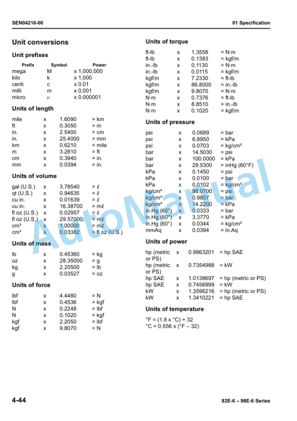
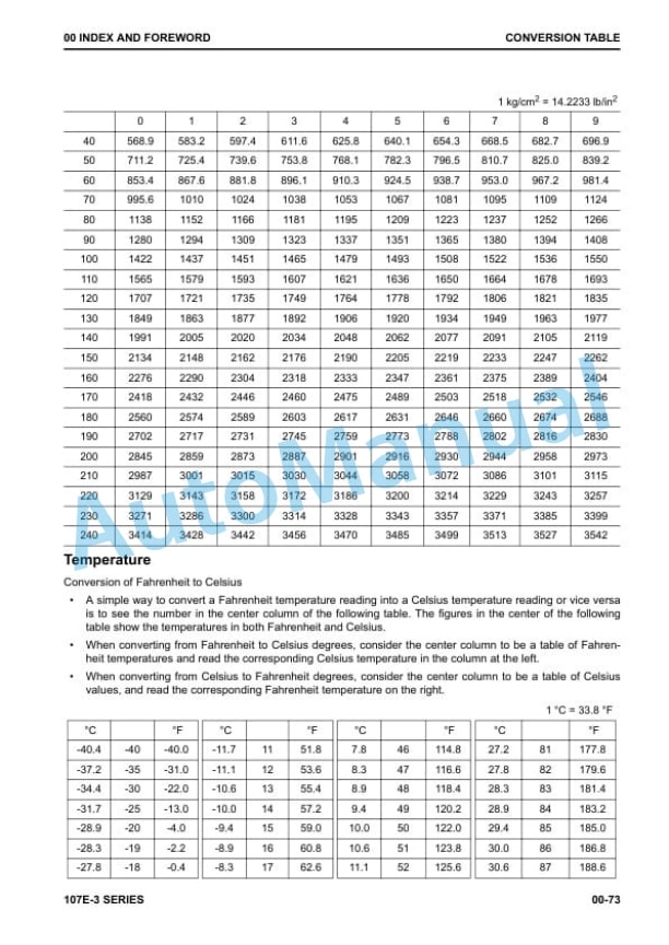
- 3.1.13. Unit conversions
- 4. Testing and adjusting
- 4.1. Testing and adjusting, Part 1
- 4.1.1. Before you begin servicing
- 4.1.2. Introduction
- 4.1.3. Periodic maintenance schedule
- 4.1.4. Periodic maintenance procedures
- 4.2. Testing and adjusting, Part 2
- 4.2.1. Before you begin servicing
- 4.2.2. Introduction
- 4.2.3. Cylinder head specifications
- 4.2.4. Camshaft and timing gear train specifications
- 4.2.5. Crankshaft and piston specifications
- 4.2.6. Cylinder block specifications
- 4.2.7. Special torque chart
- 4.2.8. Special service tools
- 4.2.9. Measuring instruments
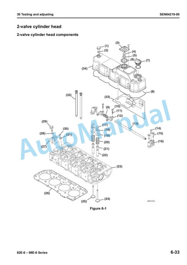
- 4.2.10. valve cylinder head
- 4.2.11. valve cylinder head
- 4.2.12. Measuring and adjusting valve clearance
- 4.2.13. Crankshaft and camshaft components
- 4.2.14. EGR system
- 4.3. Testing and adjusting, Part 3
- 4.3.1. Before you begin servicing
- 4.3.2. Introduction
- 4.3.3. Fuel system specifications
- 4.3.4. Special service tools
- 4.3.5. Measuring instruments
- 4.3.6. Fuel system diagram
- 4.3.7. Fuel system components
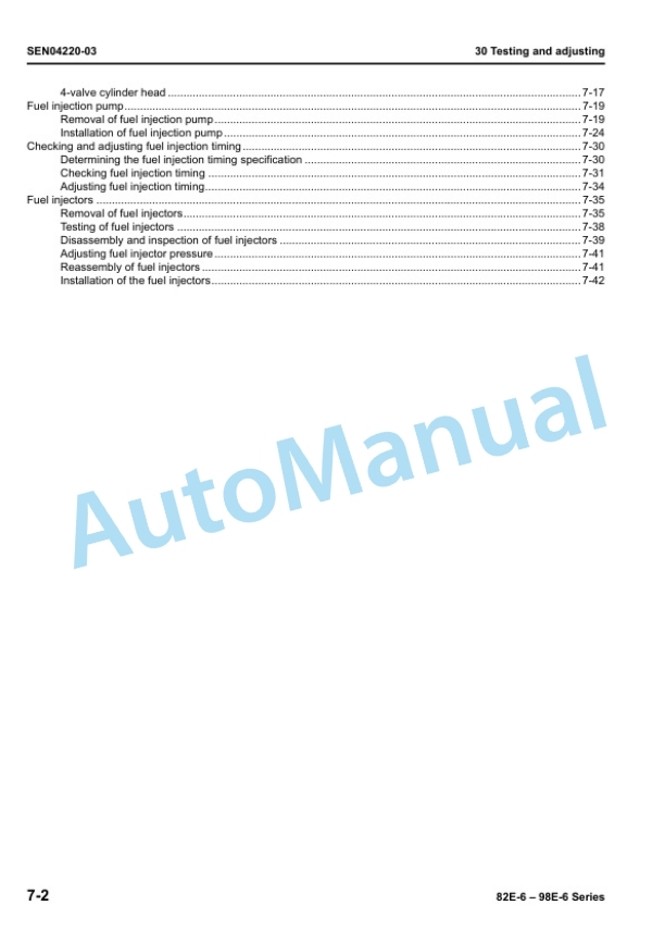
- 4.3.8. Fuel injection pump
- 4.3.9. Checking and adjusting fuel injection timing
- 4.3.10. Fuel injectors
- 4.4. Testing and adjusting, Part 4
- 4.4.1. Before you begin servicing
- 4.4.2. Introduction
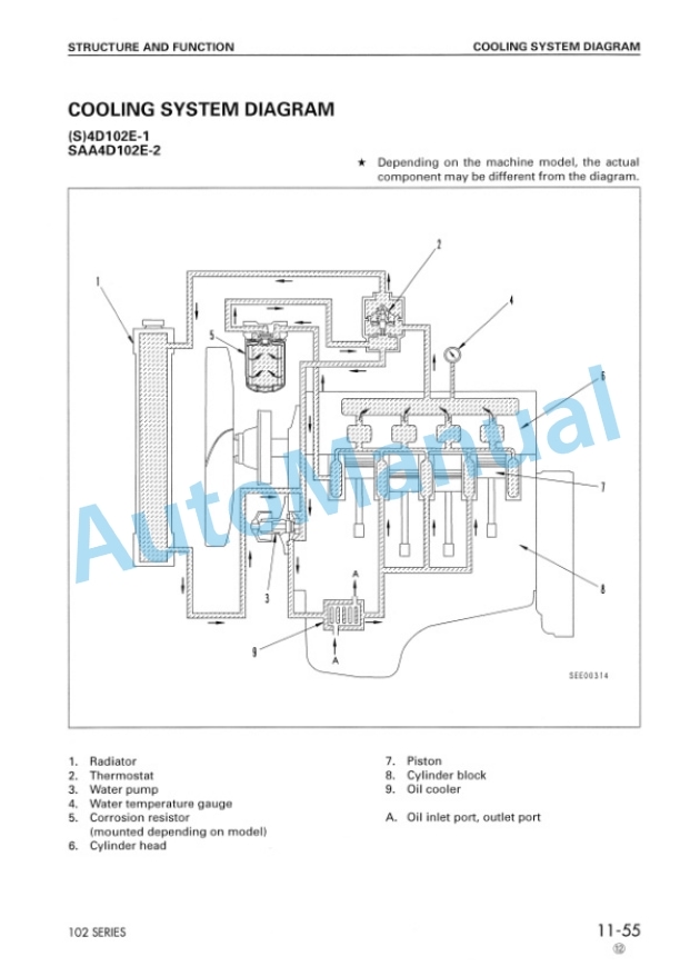
- 4.4.3. Cooling system diagram
- 4.4.4. Engine coolant pump components
- 4.4.5. Engine coolant system check
- 4.4.6. Engine coolant pump
- 4.5. Testing and adjusting, Part 5
- 4.5.1. Before you begin servicing
- 4.5.2. Introduction
- 4.5.3. Oil pump service information
- 4.5.4. Lubrication system diagram
- 4.5.5. Checking engine oil pressure
- 4.5.6. Trochoid oil pump
- 4.5.7. Trochoid oil pump
- 4.5.8. Trochoid oil pump
- 4.6. Testing and adjusting, Part 6
- 4.6.1. Before you begin servicing
- 4.6.2. Introduction
- 4.6.3. Specifications
- 4.6.4. Troubleshooting
- 4.6.5. Turbocharger components
- 4.6.6. Turbocharger component functions
- 4.6.7. Washing procedure
- 4.6.8. Periodic inspection
- 4.7. Testing and adjusting, Part 7
- 4.7.1. Before you begin servicing
- 4.7.2. Introduction
- 4.7.3. Starter motor information
- 4.7.4. Starter motor specifications
- 4.7.5. Starter motor troubleshooting
- 4.7.6. Starter motor components
- 4.7.7. Starter motor
- 4.8. Testing and adjusting, Part 8
- 4.8.1. Before you begin servicing
- 4.8.2. Introduction
- 4.8.3. Dynamo and alternator information
- 4.8.4. Alternator specifications
- 4.8.5. Dynamo specifications
- 4.8.6. Alternator troubleshooting
- 4.8.7. Alternator components
- 4.8.8. Alternator wiring diagram
- 4.8.9. Alternator standard output
- 4.8.10. Alternator
- 4.8.11. Dynamo component location
- 4.8.12. Dynamo wiring diagram
- 4.8.13. Operation of dynamo
- 4.8.14. Dynamo standard output
- 4.8.15. Testing of dynamo
- 4.8.16. Dynamo
- 5. Troubleshooting
- 5.1. Troubleshooting of mechanical system
- 5.1.1. Special service tools
- 5.1.2. Troubleshooting by measuring compression pressure
- 5.1.3. Quick reference table for troubleshooting
Rate this product
You may also like

