- Claas
- Grove
- New Holland
- Komatsu
- Kubota
- John Deere
- Linde
- Bomag
- CASE
- Clark
- JCB
- Jungheinrich
- Linde
- Yale
- Yanmar
- Manitou
- Manitowoc
- CNH
- Doosan
- Fiatagri
- Fiatallis
- Fiatallis Other Manual PDF
- Flexi Coil
- Ford New Holland
- Ford New Holland Other Manual PDF
- Huyndai
- Hypac
- Hyster
- Hyster Service Manual PDF
- Isuzu
- Kobelco
- Kohler
- Krupp
- Lombardini
- Mahindra
- Nuvera
- Perkins
- Sperry New Holland
- Utilev
- Versatile
- ZF


Komatsu D155A-5 Bull Dozer Shop Manual SEBM023302
$50.00
- Type Of Manual: Shop Manual
- Manual ID: SEBM023302
- Format: PDF
- Size: 28.8MB
- Number of Pages: 722
Category: Komatsu Shop Manual PDF
-
Model List:
- D155A-5 Bull Dozer
- 0.1. HOW TO READ THE SHOP MANUAL
- 0.2. HOISTING INSTRUCTIONS
- 0.3. METHOD OF DISASSEMBLING, CONNECTING PUSHPULL TYPE COUPLER
- 0.4. COATING MATERIALS
- 0.5. STANDARD TIGHTENING TORQUE
- 0.6. ELECTRIC WIRE CODE
- 0.7. CONVERSION TABLE
- 0.8. UNITS
- 1. General
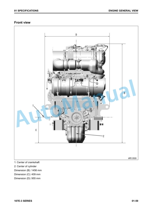
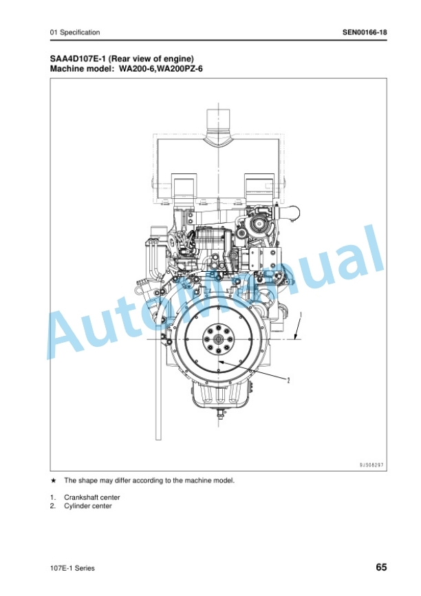
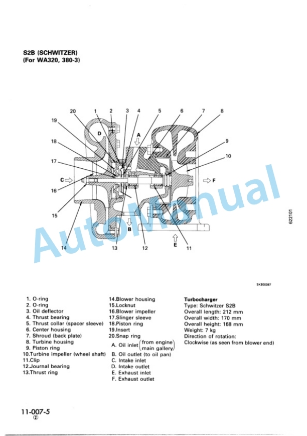
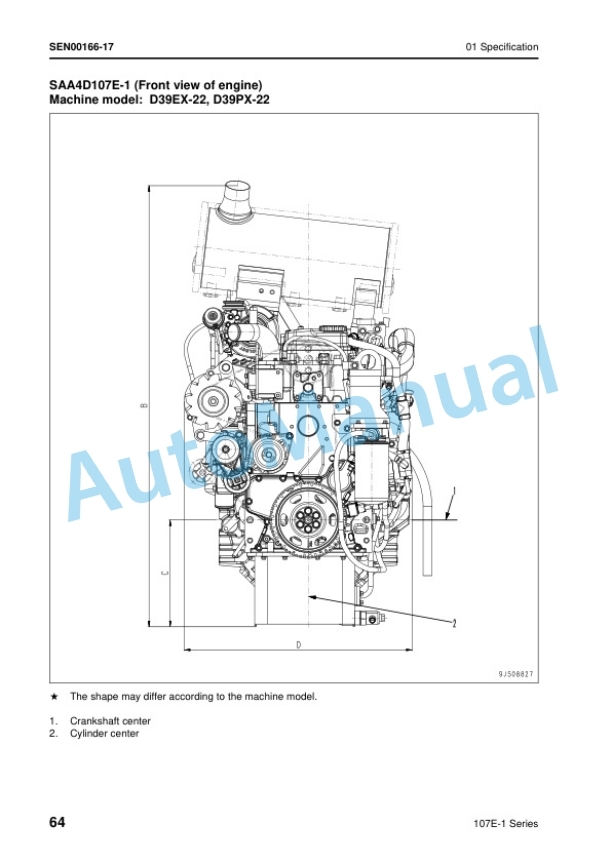
- 1.1. Specification drawing
- 1.2. Specifications
- 1.3. Weight table
- 1.4. Table of fuel, coolant and lubricants
- 2. Structure and function
- 2.1. Radiator
- 2.2. Oil cooler
- 2.3. Engine control
- 2.4. Power train
- 2.5. Power train system
- 2.6. Power train unit mount
- 2.7. Overall drawing of power train unit
- 2.8. Power train hydraulic piping diagram
- 2.9. Power train hydraulic system drawing
- 2.10. Damper, universal joint
- 2.11. Torque converter, PTO
- 2.12. Transmission control
- 2.13. Transmission
- 2.14. Transmission control valve
- 2.15. Main relief valve
- 2.16. Lubrication relief valve
- 2.17. Steering, brake control
- 2.18. Bevel gear shaft, steering clutch, steering brake
- 2.19. Steering control valve
- 2.20. Reducing valve
- 2.21. Scavenging pump strainer
- 2.22. Power train pump strainer
- 2.23. Power train oil filter
- 2.24. Final drive
- 2.25. Radiator guard
- 2.26. Main frame, underguard
- 2.27. Track frame
- 2.28. Recoil spring
- 2.29. Track roller bogie
- 2.30. Suspension
- 2.31. Work equipment hydraulic piping diagram
- 2.32. PPC control piping diagram
- 2.33. Work equipment control
- 2.34. Work equipment hydraulic system diagram
- 2.35. Hydraulic tank and filter
- 2.36. PPC charge valve
- 2.37. Accumulator
- 2.38. PPC lock valve
- 2.39. PPC valve
- 2.40. Main control valve
- 2.41. Operation of main control valve
- 2.42. Operation of work equipment control circuit
- 2.43. Piston valve
- 2.44. Quick drop valve
- 2.45. Cylinder stay
- 2.46. Work equipment
- 2.47. Pin puller switch
- 2.48. Pin puller solenoid valve
- 2.49. Tilt/pitch selector switch
- 2.50. Pitch solenoid valve
- 2.51. Cab mount
- 2.53. Air conditioner
- 2.54. Electrical wiring diagram
- 2.55. Machine monitor system
- 2.56. Sensors
- 2.57. Engine starting system
- 3. Testing and adjusting
- 3.1. Standard value tables
- 3.1.1. Standard value table for engine related parts
- 3.1.2. Standard value table for chassis related parts
- 3.1.3. Standard value table for machine monitor
- 3.2. Testing and adjusting
- 3.2.1. Tools for testing, adjusting, and troubleshooting
- 3.2.2. Measuring engine speed
- 3.2.3. Measuring exhaust color
- 3.2.4. Adjusting valve clearance
- 3.2.5. Measuring compression pressure
- 3.2.6. Measuring blowby
- 3.2.7. Measuring engine oil pressure
- 3.2.8. Testing and adjusting fuel injection timing
- 3.2.9. Testing and adjusting alternator belt tension
- 3.2.10. Measuring exhaust temperature
- 3.2.11. Measuring air supply pressure (boost pressure)
- 3.2.12. Measuring torque converter stall speed
- 3.2.13. Measuring torque converter stall hydraulic pump relief (full stall) speed
- 3.2.14. Adjusting fuel control linkage
- 3.2.15. Adjusting decelerator pedal
- 3.2.16. Adjusting joystick (steering, directional, gear shift lever), parking lever linkage
- 3.2.17. Adjusting brake pedal linkage
- 3.2.18. Adjusting work equipment control linkage
- 3.2.19. Testing and adjusting work equipment control circuit pressure
- 3.2.20. Measuring PPC valve output pressure
- 3.2.21. Adjusting PPC valve
- 3.2.22. Measuring onoff solenoid valve output pressure
- 3.2.23. Measuring power train oil pressure
- 3.2.24. Testing and adjusting work equipment main relief pressure
- 3.2.25. Bleeding air from hydraulic cylinders
- 3.2.26. Releasing remaining pressure in hydraulic circuit
- 3.2.27. Checking location of cause of hydraulic drift of blade and ripper
- 3.2.28. Measuring leakage inside cylinder
- 3.2.29. Adjusting semiUtiltdozer
- 3.2.30. Adjusting clearance of idler
- 3.2.31. Simple procedure for testing brake performance
- 3.3. Troubleshooting
- 3.3.1. Points to remember when troubleshooting
- 3.3.2. Sequence of events in troubleshooting
- 3.3.3. Points to remember when carrying out maintenance
- 3.3.4. Checks before troubleshooting
- 3.3.5. Type of connector and position of installation
- 3.3.6. Connector arrangement diagram
- 3.3.7. Connection table for connector pin numbers
- 3.3.8. Method of using troubleshooting charts
- 3.3.9. Troubleshooting of electrical system (E mode)
- 3.3.10. Troubleshooting of hydraulic and mechanical systems (H mode)
- 3.3.11. Troubleshooting of machine monitor system (M mode)
- 4. DISASSEMBLY AND ASSEMBLY
- 4.1. METHOD OF USING MANUAL
- 4.2. PRECAUTIONS WHEN CARRYING OUT OPERATION
- 4.3. SPECIAL TOOL LIST
- 4.4. SPECIAL TOOL SKETCH
- 4.5. ENGINE OIL COOLER CORE
- 4.5.1. REMOVAL
- 4.5.2. INSTALLATION
- 4.6. FUEL INJECTION PUMP
- 4.7. ENGINE FRONT SEAL
- 4.7.1. REMOVAL
- 4.7.2. INSTALLATION
- 4.8. ENGINE REAR SEAL
- 4.9. AIR CONDITIONER COMPRESSOR
- 4.9.1. REMOVAL
- 4.9.2. INSTALLATION
- 4.10. AIR CONDITIONER CONDENSER
- 4.11. RADIATOR, OIL COOLER, GUARD
- 4.12. HYDRAULIC COOLER
- 4.13. POWER TRAIN UNIT
- 4.14. TORQUE CONVERTER
- 4.14.1. DISASSEMBLY
- 4.14.2. ASSEMBLY
- 4.15. TORQFLOW TRANSMISSION
- 4.16. POWER TRAIN, LUBRICATION PUMP
- 4.16.1. REMOVAL
- 4.16.2. INSTALLATION
- 4.17. SCAVENGING PUMP
- 4.17.1. REMOVAL
- 4.17.2. INSTALLATION
- 4.18. POWER TRAIN MAIN RELIEF VALVE
- 4.18.1. REMOVAL
- 4.18.2. INSTALLATION
- 4.18.3. DISASSEMBLY
- 4.18.4. ASSEMBLY
- 4.19. TRANSMISSION CONTROL VALVE
- 4.20. STEERINGCONTROL VALVE
- 4.20.1. CHECKING BEFORE REMOVAL
- 4.20.2. REMOVAL (NORMAL)
- 4.20.3. REMOVAL (WHEN THERE IS ABNORMALITY INSIDE TRACK FRAME)
- 4.20.4. INSTALLATION
- 4.20.5. OVERALL DISASSEMBLY
- 4.20.6. OVERALL ASSEMBLY
- 4.21. PRESSFITTING JIG DIMENSION TABLE FOR LINK PRESS
- 4.22. EQUALIZER BAR SIDE BUSHING
- 4.23. HYDRAULIC, PPC PUMP
- 4.23.1. REMOVAL
- 4.23.2. INSTALLATION
- 4.24. MAIN CONTROL VALVE
- 4.24.1. REMOVAL
- 4.24.2. INSTALLATION
- 4.24.3. DISASSEMBLY
- 4.24.4. ASSEMBLY
- 4.25. PPC CHARGE VALVE
- 4.25.1. REMOVAL
- 4.25.2. INSTALLATION
- 4.25.3. DISASSEMBLY
- 4.25.4. ASSEMBLY
- 4.26. BLADE PPC VALVE
- 4.26.1. REMOVAL
- 4.26.2. INSTALLATION
- 4.27. RIPPER PPC VALVE
- 4.27.1. REMOVAL
- 4.27.2. INSTALLATION
- 4.28. BLADE PPC VALVE
- 4.28.1. DISASSEMBLY
- 4.28.2. ASSEMBLY
- 4.29. BLADE LIFT CYLINDER
- 4.29.1. REMOVAL
- 4.29.2. INSTALLATION
- 4.30. BLADE TILT CYLINDER
- 4.30.1. REMOVAL
- 4.30.2. INSTALLATION
- 4.31. RIPPER LIFT CYLINDER
- 4.31.1. REMOVAL
- 4.31.2. INSTALLATION
- 4.32. RIPPER TILT CYLINDER
- 4.32.1. REMOVAL
- 4.32.2. INSTALLATION
- 4.33. HYDRAULIC CYLINDER
- 4.34. MULTISHANK RIPPER
- 5. Maintenance standard
- 5.1. Engine mount
- 5.2. Power train unit mount
- 5.3. Damper, universal joint
- 5.4. Torque converter, PTO
- 5.5. Transmission
- 5.6. Transmission control valve
- 5.7. Main relief valve
- 5.8. Bevel gear shaft, steering clutch, steering brake
- 5.9. Steering control valve
- 5.10. Scavenging pump
- 5.11. Power train pump, lubrication pump
- 5.12. Final drive
- 5.13. Main frame
- 5.14. Track frame
- 5.15. Recoil spring
- 5.16. Track roller bogie
- 5.17. Idler
- 5.18. Track roller
- 5.19. Carrier roller
- 5.20. Recoil spring
- 5.21. Track shoe (Dry type track)
- 5.22. Track shoe (Sealed and Lubricated Track)
- 5.23. Suspension
- 5.24. Hydraulic, PPC charge pump
- 5.25. PPC charge valve
- 5.26. PPC valve
- 5.27. Main control valve
- 5.28. Work equipment cylinder
- 5.29. Quick drop valve
- 5.30. Cylinder stay
- 5.31. Work equipment
- 6. Others
- 6.1. Hydraulic circuit diagram
- 6.1.1. Power train hydraulic circuit diagram
- 6.1.2. Work equipment hydraulic circuit diagram
- 6.2. Electrical circuit diagram
- 6.2.1. ELECTRICAL CIRCUIT DIAGRAM
- 6.2.2. Cab electrical circuit diagram
Rate this product
You may also like


Komatsu Shop Manual PDF
$50.00

- Claas
- Grove
- New Holland
- Komatsu
- Kubota
- John Deere
- Linde
- Bomag
- CASE
- Clark
- JCB
- Jungheinrich
- Linde
- Yale
- Yanmar
- Manitou
- Manitowoc
- CNH
- Doosan
- Fiatagri
- Fiatallis
- Fiatallis Other Manual PDF
- Flexi Coil
- Ford New Holland
- Ford New Holland Other Manual PDF
- Huyndai
- Hypac
- Hyster
- Hyster Service Manual PDF
- Isuzu
- Kobelco
- Kohler
- Krupp
- Lombardini
- Mahindra
- Nuvera
- Perkins
- Sperry New Holland
- Utilev
- Versatile
- ZF