Komatsu D355C-3 Pipe Layer Field Assembly Instruction GEN00024-03
$20.00
- Type Of Manual: Field Assembly Instruction
- Manual ID: GEN00024-03
- Format: PDF
- Size: 4.1MB
- Number of Pages: 95
-
Model List:
- D355C-3 Pipe Layer
- 1. COVER
- 2. Preface
- 3. CONTENTS
- 3.1. SPECIFICATIONS
- 3.2. PRECAUTIONS FOR FIELD ASSEMBLY
- 3.2.1. Selection of workplace
- 3.2.2. Preparation and check of slings and tools
- 3.2.3. kCheck of actual work
- 3.2.4. Before starting the work, layout the parts to be assembled.
- 3.2.5. Before starting the work, read this manual thoroughly and keep the precautions in your mind.
- 3.2.6. The supervisor shall write down the precautions for each work process and explain them to the workers.
- 3.2.7. Hold a meeting every morning to check todays work plan and safe work. Precaution When assembling, refer to the operation manual as well as this manual.
- 3.3. ASSEMBLY PROCEDURE, NECESSARY EQUIPMENT, AND SCHEDULE
- 3.4. POSITION FOR TRANSPORTATION
- 3.4.1. Chassis
- 3.4.2. Boom assembly
- 3.4.3. Counterweight bracket assembly
- 3.4.4. Counterweight
- 3.4.5. Frame (Boom side)
- 3.4.6. Lift link (Large)
- 3.4.7. Frame (Winch side)
- 3.4.8. Removed parts
- 3.4.10. Exterior parts (for hydraulic winch specification only
- 3.5. LIST OF TOOLS FOR FIELD ASSEMBLY
- 3.6. COATING MATERIALS LIST
- 3.6.1. Remove the rain cap (used for transportation) and install exhaust pipe (1).
- 3.6.2. Install rain cap (20Y0112300).
- 3.6.3. Installation of head lamp
- 3.6.4. Installation of side lamp
- 3.6.5. Install frame (on the winch side) (2) on the right side of the chassis carefully.
- 3.6.6. Taking care of the following points, install frame (on the boom side) (3) on the left side of the chassis.
- 3.6.7. Adjusting boom kickout
- 3.6.8. Install large link (9), small link (10), front cylinder (11) 50C specification (13), and rear cylinder (12) 50C specification (14) to bracket (8) to make the subassembly.
- 3.6.9. With the engine stopped, set the counterweight control lever in the RETRACT and EXTRACT positions 2 3 times to release the residual pressure in the cylinder piping.
- 3.6.10. Sling the subassembly in 1 above and install it to the gatetype frame according to the following procedure.
- 3.6.11. Connect the cylinder piping. Remove the oil stop plugs of the cylinder and tubes and install the hydraulic hoses, taking care…
- 3.6.12. Supply grease to each part. (See A10 Greasing)
- 3.6.13. After finishing the installation work, bleed air from each cylinder according to the following procedure, and then check the hydraulic oil level.
- 3.6.14. After installing the counterweight, operate the counterweight control lever to check that the hydraulic hoses do not interfere with other parts and oil is not leaking.
- 3.6.15. Install the counterweight segment securely according to the following procedure.
- 3.6.16. Installation of head lamp (For only machine for CIS)
- 3.6.17. Installation of cab
- 3.6.18. Installation of hot water heater pipes
- 3.6.19. Installation of cab power supply
- 3.6.20. Install the floor mats (1), (2).
- 3.6.21. Installation of accessories
- 3.6.22. Installation of air conditioner piping
- 3.6.23. Installation of overwind prevention device (if equipped)
- 3.6.24. Installation of angle indicator and hook stabilizer rope
- 3.6.25. Installation of wire rope retainer lock (If equipped)
- 3.6.26. Check of hot water circuit of heater
- 3.6.27. Wiring in dashboard
- 3.6.28. Check of power supply
- 3.6.29. Charging with refrigerant
- 3.6.30. Wiring around compressor
- 3.6.31. Using a grease pump, supply grease to the grease fittings indicated by arrows.
- 3.6.32. After supplying grease, wipe off the projected grease.
- 3.6.33. Installation of handrail around battery case (rear left of machine).
- 3.6.34. Installation of step and mirror (rear right of machine).
- 3.6.35. Counterweight cylinder
- 3.6.36. Inspection of paint
- 3.6.37. Check of door lock
- 3.6.38. Check of OPEN lock (if equipped)
- 3.6.39. Inspection of boom kickout
- 3.6.40. Check of operation of moment limiter (if equipped)
- 3.6.41. Check of operation of moment limiter (if equipped)
- 3.6.42. Check of operation of overwind prevention device (if equipped)
Komatsu Operation and Maintenance Manual PDF
Komatsu 330M Dump Truck Operation and Maintenance Manual DG745
Komatsu Operation and Maintenance Manual PDF
Komatsu 450FXL-1 Crawler Feller Buncher Operation and Maintenance Manual CEAM023802
Komatsu Operation and Maintenance Manual PDF
Komatsu 101 Basics Forklift Truck Operation and Maintenance Manual
Komatsu Operation and Maintenance Manual PDF
Komatsu 210M Dump Truck Operation and Maintenance Manual DG615
Komatsu Operation and Maintenance Manual PDF
Komatsu 730E Dump Truck Operation and Maintenance Manual CEAM014901
Komatsu Operation and Maintenance Manual PDF
Komatsu 210M Dump Truck Operation and Maintenance Manual DG714
Komatsu Operation and Maintenance Manual PDF
Komatsu 530M Dump Truck Operation and Maintenance Manual DG716
Komatsu Operation and Maintenance Manual PDF
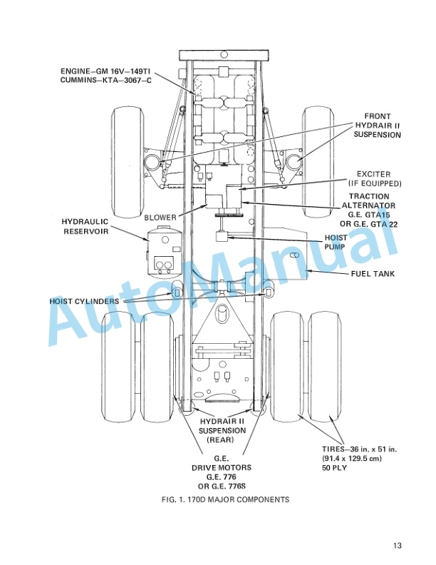
Komatsu 170D Dump Truck Operation and Maintenance Manual DG534
Komatsu Operation and Maintenance Manual PDF
Komatsu 150A, 150FA Crane Operation and Maintenance Manual CEAMC20081
Komatsu Operation and Maintenance Manual PDF
Komatsu 330M Dump Truck Operation and Maintenance Manual DG713