Komatsu FB22H-3R, FB25H-3R, FB25HG-3R, FB30H-3R Workshop Manual 40248042304EN
$40.00
- Type Of Manual: Workshop Manual
- Manual ID: 40248042304EN
- Format: PDF
- Size: 9.4MB
- Number of Pages: 286
Category: Komatsu Shop Manual PDF
-
Model List:
- FB22H-3R
- FB25H-3R
- FB25HG-3R
- FB30H-3R
- 1.1. Header
- 1.2. Table of contents
- 1.2.1. General information
- 1.2.1.1. Product information
- 1.2.1.1.1. Instruction and maintenance manual
- 1.2.1.1.2. Definition of Direction of Travel
- 1.2.1.1.3. General Forklift Description
- 1.2.1.1.4. Overall dimensions
- 1.2.1.1.5. Technical Data
- 1.2.1.1.6. Tyre characteristics
- 1.2.1.1.7. Forklift capacities Model 2200 kg Masts vertical with forks 1400 mm max.
- 1.2.1.1.8. Forklift capacities Model 2500 kg short pitch Masts vertical with forks 1400 mm max.
- 1.2.1.1.9. Forklift capacities Model 2500 kg long pitch Masts vertical with forks 1400 mm max.
- 1.2.1.1.10. Forklift capacities Model 3000 kg Masts vertical with forks 1400 mm max.
- 1.2.1.1.11. Alternative lift characteristics
- 1.2.1.1.12. Abbreviations key
- 1.2.1.1.13. Pneumatic tyre inflation pressure
- 1.2.1.1.14. Lamps
- 1.2.1.1.15. Battery dimensions and weights
- 1.2.1.1.16. Internal accessibility
- 1.2.1.1.17. Safety Devices
- 1.2.1.1.18. Transporting the Forklift
- 1.2.1.1.19. Forklift Towing
- 1.2.1.1.20. Loading and Unloading the Forklift
- 1.2.1.2. Safety precautions
- 1.2.1.2.1. Description of safety symbols
- 1.2.1.2.2. Operations Preliminary to Maintenance
- 1.2.1.2.3. To avoid accidents
- 1.2.1.2.4. General safety Regulations
- 1.2.1.2.5. Safety Regulations Relative to Operating Materials
- 1.2.2. Service
- 1.2.2.1. Maintenance
- 1.2.2.1.1. Preliminary operations before commissioning
- 1.2.2.1.2. Synoptic Table of Maintenance Operations
- 1.2.2.1.3. Supply Table
- 1.2.3. Diagnostics
- 1.2.3.1. Diagnostic software
- 1.2.3.1.1. Connection between the diagnostics PC and the forklift
- 1.2.3.1.2. Software
- 1.2.3.1.3. Description of the menus in the WINPCCONSOLE software
- 1.2.3.1.4. Description of the PARAMETER menu
- 1.2.3.1.5. Description of the TESTER menu
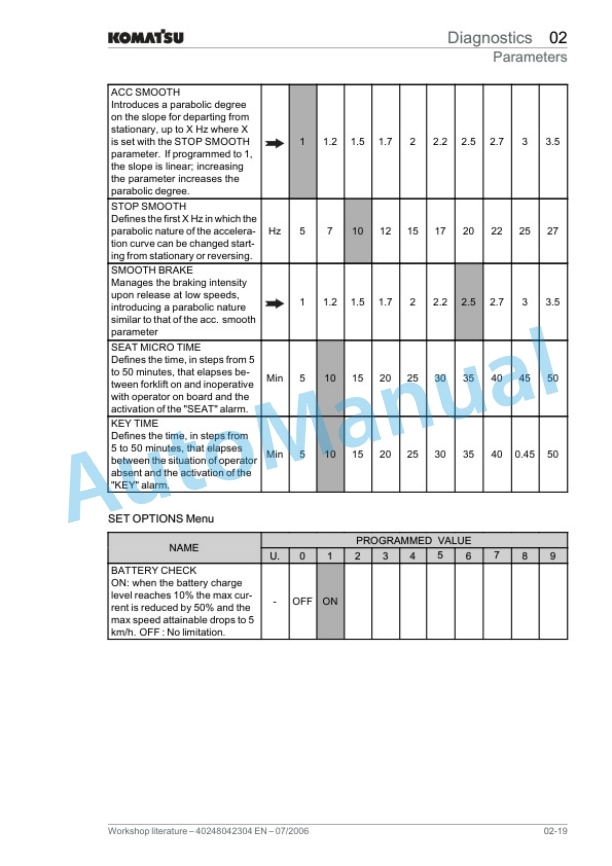
- 1.2.3.2. Parameters
- 1.2.3.2.1. Introduction
- 1.2.3.2.2. Parameters of the DUAL AC Master module
- 1.2.3.2.3. AC3 module parameters
- 1.2.3.2.4. Smart Display
- 1.2.3.2.5. TESTER Function
- 1.2.3.2.6. Speed reductions
- 1.2.3.3. Alarms
- 1.2.3.3.1. General information on the alarms
- 1.2.3.3.2. Alarms of the DUAL AC module
- 1.2.3.3.3. Alarms of the AC3 module
- 1.2.3.3.4. Alarms of the SMART DISPLAY module
- 1.2.3.4. Analogue signals
- 1.2.3.4.1. Analogue signal acquisition
- 1.2.4. Drive motor
- 1.2.4.1. Asynchronous motors
- 1.2.4.1.1. Features of the asynchronous motors
- 1.2.4.1.2. Checking the asynchronous motors
- 1.2.4.2. Front axle motors
- 1.2.4.2.1. Drive motor technical data
- 1.2.4.2.2. Drive motor checks
- 1.2.4.2.3. Motor temperature sensor
- 1.2.4.2.4. Drive motor decomposition
- 1.2.5. Gearbox
- 1.2.5.1. Front axle
- 1.2.5.1.1. Front axle technical data
- 1.2.5.1.2. Front axle layout
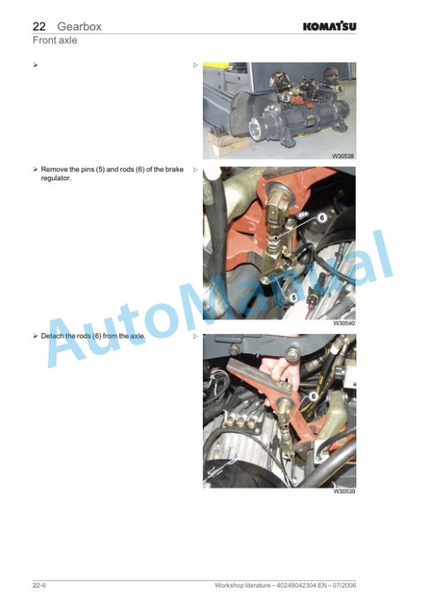
- 1.2.5.1.3. Removal of front axle with drive motors
- 1.2.5.1.4. Front axle reconnection
- 1.2.5.1.5. Front axle disassembly
- 1.2.5.1.6. Front axle reassembly
- 1.2.5.2. Reducer
- 1.2.5.2.1. Front axle reducer layout
- 1.2.5.2.2. Front axle reduction gear disassembly/reassembly
- 1.2.5.2.3. Reduction gear oil level check
- 1.2.5.2.4. Reducer oil change
- 1.2.6. Vehicle
- 1.2.6.1. Bonnets
- 1.2.6.1.1. Bonnet layout
- 1.2.6.1.2. Right side bonnet removal/reassembly
- 1.2.6.1.3. Left side bonnet removal/reassembly
- 1.2.6.1.4. Battery hood removal/reassembly
- 1.2.6.1.5. Electronic panel bonnet removal/reassembly
- 1.2.6.1.6. Distributor hood removal/reassembly
- 1.2.6.1.7. Removal/reassembly of the operator footboard
- 1.2.6.2. Counterweight
- 1.2.6.2.1. Counterweight disconnection
- 1.2.6.2.2. Counterweight reconnection
- 1.2.7. Drivers seat
- 1.2.7.1. Fairing
- 1.2.7.1.1. Fairing removal/reassembly
- 1.2.7.1.2. Steering column panels removal/reassembly
- 1.2.7.2. Protective roof
- 1.2.7.2.1. Removal of the protective roof
- 1.2.7.2.2. Protective roof refitting
- 1.2.7.2.3. Lamp changes
- 1.2.8. Steering system
- 1.2.8.1. Hydraulic steering circuit
- 1.2.8.1.1. Power steering circuit tube connection diagram
- 1.2.8.2. Steering solenoid valve
- 1.2.8.2.1. Steering distributor technical data
- 1.2.8.2.2. Steering distributor removal
- 1.2.8.2.3. Steering distributor reassembly
- 1.2.8.3. Steering column
- 1.2.8.3.1. Steering column removal/reassembly
- 1.2.8.3.2. Replacement of the steering column joint
- 1.2.8.4. Steering axle
- 1.2.8.4.1. Steering axle technical data
- 1.2.8.4.2. Steering axle disconnection
- 1.2.8.4.3. Steering axle reconnection
- 1.2.8.4.4. Steering axle lubrication
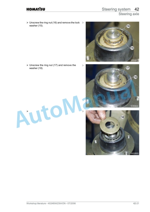
- 1.2.8.4.5. Replacement of the steering axle bearings
- 1.2.8.4.6. Steering axle potentiometer
- 1.2.8.4.7. Replacement of the steering axle potentiometer
- 1.2.8.5. Steering cylinder
- 1.2.8.5.1. Steering cylinder disconnection
- 1.2.8.5.2. Steering cylinder reconnection
- 1.2.8.5.3. Replacement of the steering cylinder gaskets
- 1.2.8.5.4. Replacement of the cylinder connecting rod ball joints
- 1.2.9. Wheel and tyres
- 1.2.9.1. Miscellaneous
- 1.2.9.1.1. Safety regulations for wheels and rims
- 1.2.9.1.2. General information for changing tyres
- 1.2.9.1.3. Tyrewear check
- 1.2.9.2. Changing wheels
- 1.2.9.2.1. Changing the front wheel
- 1.2.9.2.2. Changing the rear wheel.
- 1.2.9.3. Wheel disassembly
- 1.2.9.3.1. Disassembly/assembly of tyres on rims with movable flange
- 1.2.9.3.2. Quick tyres assembly/disassembly
- 1.2.9.4. Tightening torques
- 1.2.9.4.1. Tightening torques for single wheels
- 1.2.10. Brake system
- 1.2.10.1. Service brake
- 1.2.10.1.1. Brake pedal
- 1.2.10.1.2. Brake pedal potentiometer
- 1.2.10.1.3. Brake pedal removal/reassembly
- 1.2.10.1.4. Replacement of the brake pedal spring
- 1.2.10.1.5. Stop micro replacement
- 1.2.10.1.6. Replacement of the brake pedal potentiometer
- 1.2.10.1.7. Service brake adjustment
- 1.2.10.2. Parking brake
- 1.2.10.2.1. Microswitch features
- 1.2.10.2.2. Parking brake removal/reassembly
- 1.2.10.2.3. Parking brake wire replacement
- 1.2.10.2.4. Replacement of the parking brake microswitch
- 1.2.10.2.5. Parking brake adjustment
- 1.2.10.3. Brake group
- 1.2.10.3.1. Brake pad replacement
- 1.2.11. Controls
- 1.2.11.1. Accelerator pedal
- 1.2.11.1.1. Accelerator pedal
- 1.2.11.1.2. Accelerator pedal potentiometer
- 1.2.12. Display elements
- 1.2.12.1. Display
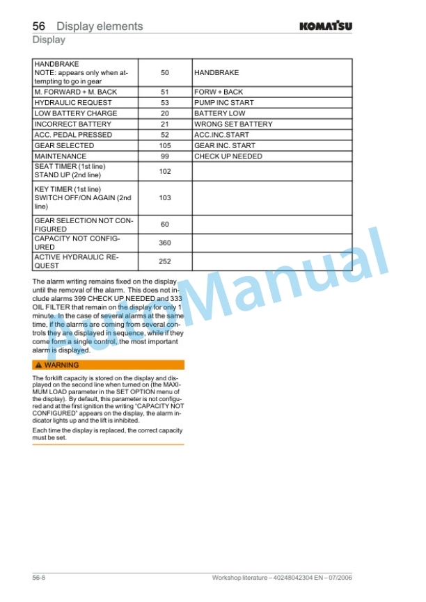
- 1.2.12.1.1. Multifunction panel
- 1.2.12.1.2. State of the display on ignition
- 1.2.12.1.3. State of the display during normal forklift operation
- 1.2.12.1.4. State of the display during an alarm situation
- 1.2.12.1.5. Plate data
- 1.2.12.1.6. Display operation
- 1.2.13. Electrical system
- 1.2.13.1. CAN BUS
- 1.2.13.1.1. CAN BUS
- 1.2.13.1.2. CAN BUS Application
- 1.2.13.1.3. Brake pedal potentiometer
- 1.2.13.2. Drive electrical system
- 1.2.13.2.1. Functions of the DUAL AC module
- 1.2.13.2.2. Plate data
- 1.2.13.2.3. DUAL AC connectors
- 1.2.13.2.4. Software program and parameterizations
- 1.2.13.3. Hydraulic functions electrical system
- 1.2.13.3.1. Functions of the AC3 module
- 1.2.13.3.2. Plate data
- 1.2.13.3.3. AC3 Connectors
- 1.2.13.3.4. Software program and parameterizations
- 1.2.13.4. Electrical system components
- 1.2.13.4.1. Contactors
- 1.2.13.4.2. Fuses
- 1.2.13.4.3. DC/DC Converter
- 1.2.13.4.4. Emergency pushbutton
- 1.2.13.4.5. Buzzer
- 1.2.13.4.6. Fans
- 1.2.13.4.7. Encoder description
- 1.2.13.4.8. Lamps
- 1.2.13.4.9. Protection of the electrical system
- 1.2.14. Hydraulic equipment
- 1.2.14.1. Solenoid valve
- 1.2.14.1.1. Lifting hall sensor
- 1.2.14.1.2. Reed contacts
- 1.3. Annex
- 1.3.1. A Diagrams
- 1.3.1.1. Circuit diagrams
- 1.3.1.1.1. Electrical circuit plan sheet 1/1
- 1.3.1.2. Hydraulic diagrams
- 1.3.1.2.1. Hydraulic system plan sheet 1/1
- 1.3.1.3. Flow diagrams
- 1.3.1.3.1. Flow chart of functions on display
Rate this product
You may also like
Komatsu Shop Manual PDF
$40.00

