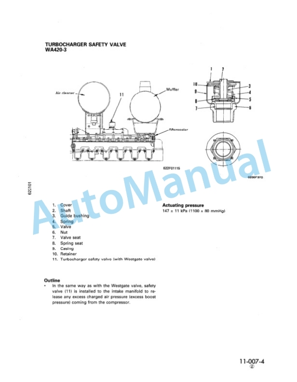
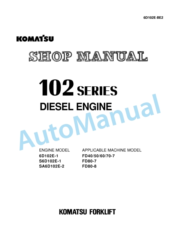
Komatsu FG10-17, FG14-17, FG15-17, FG18-17, FG15H-17, FG18H-17, FD15-17, FD18-17 Forklift Truck Shop Manual BEA17E1-01
$40.00
- Type Of Manual: Shop Manual
- Manual ID: BEA17E1-01
- Format: PDF
- Size: 15.7MB
- Number of Pages: 275
Category: Komatsu Shop Manual PDF
-
Model List:
- FG10-17 Forklift Truck
- FG14-17 Forklift Truck
- FG15-17 Forklift Truck
- FG18-17 Forklift Truck
- FG15H-17 Forklift Truck
- FG18H-17 Forklift Truck
- FD15-17 Forklift Truck
- FD18-17 Forklift Truck
- 1. Title Page BEA17E101
- 2. Section Index
- 3. General and Specifications
- 3.1. Specifications
- 3.2. Periodic Replacement of Consumable Parts
- 3.3. Safety Items for Maintenance
- 3.4. Standard Tightening Torque for Bolts
- 3.5. Standard Tightening Torque for Pipe Joints
- 4. Testing and Adjusting
- 4.1. Service Data (Gasoline Engine Lift Truck)
- 4.2. Service Data (Diesel Engine Lift Truck)
- 4.3. Gasoline Engine
- 4.4. Diesel Engine
- 4.5. Air Cleaner
- 4.6. Method of Adjusting Ignition Timing
- 4.7. Method of Adjusting Fuel Injection Timing
- 4.8. Measuring Method for Compression
- 4.9. Adjustment Method of Valve Clearance
- 4.10. Tightening Torque for Cylinder Mounting Bolts
- 4.11. Differential Case
- 4.12. TORQFLOW Transmission Case (TORQFLOW Truck Only)
- 4.13. Hydraulic Tank
- 4.14. Measuring Hydraulic Drift of Lift Cylinder, Tilt Cylinder
- 4.15. Adjusting the Clutch/Brake Pedal (Clutch Type Truck Only)
- 4.16. Adjusting Inching/Brake Pedal (TORQFLOW Type Truck)
- 4.17. Adjusting Accelerator Pedal (H15, H20II Engine)
- 4.18. Adjusting Accelerator Pedal (4D92E Engine)
- 4.19. Adjusting Parking Brake Lever
- 4.20. Bleeding Air
- 4.21. Adjusting SpringUp Angle of Steering Column
- 4.22. (FuelLubricants) Gasoline Engine Lift Truck
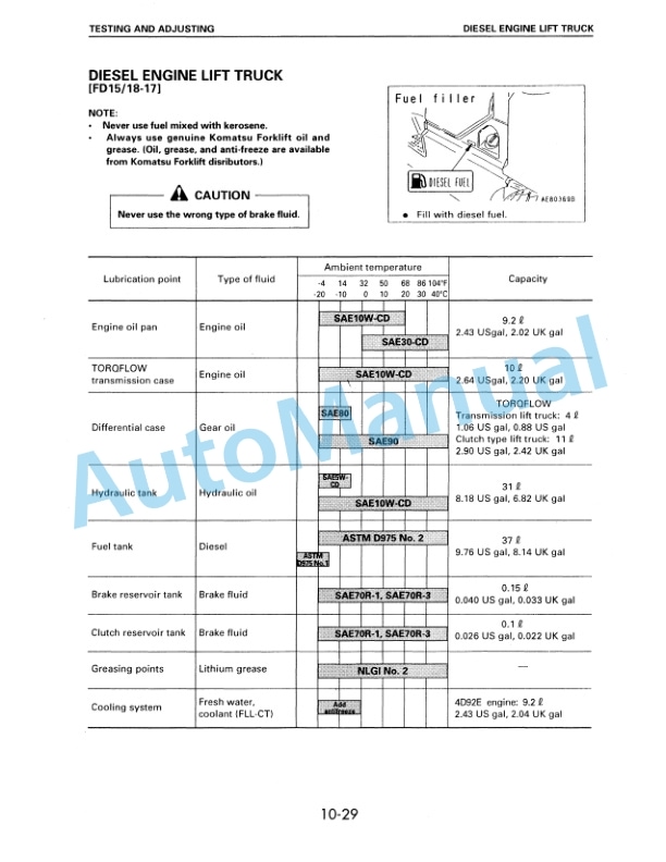
- 4.23. (FuelLubricants) Diesel Engine Lift Truck
- 4.24. Check Items for Each Equipment
- 5. Removal and Installation
- 5.1. Overall Assembly and Disassembly Drawing
- 5.2. Engine Mounting Bolt
- 5.3. Weight Table
- 5.4. Mast
- 5.5. Lift Cylinder
- 5.6. Engine
- 5.7. Clutch or Torque Converter, Transmission and Front Axle
- 5.8. Rear Axle, Power Steering
- 5.9. Wheel Brake
- 6. Disassembly and Assembly
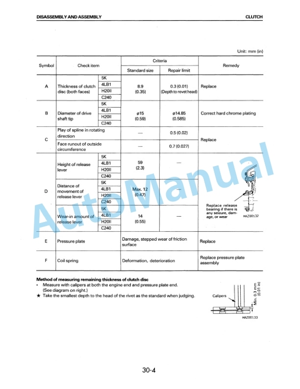
- 6.1. Clutch
- 6.2. Clutch Master Cylinder
- 6.3. Clutch Release Cylinder
- 6.4. Clutch Transmission
- 6.5. Torque Converter
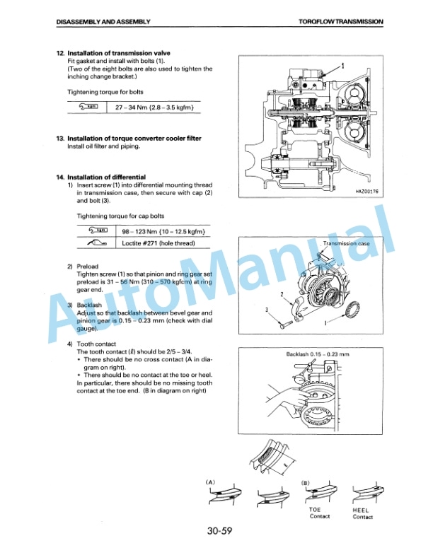
- 6.6. TORQFLOW Transmission
- 6.7. Differential
- 6.8. Front Axle
- 6.9. Wheel Brake
- 6.10. Brake Master Cylinder
- 6.11. Combination Switch
- 6.12. Steering Gear Box
- 6.13. Power Steering Cylinder
- 7. Maintenance Standard
- 7.1. Clutch Release Cylinder
- 7.2. Clutch
- 7.3. Clutch Transmission
- 7.4. Torque Converter
- 7.5. TORQFLOW Transmission
- 7.6. Differential
- 7.7. Wheel Brake
- 7.8. Brake Master Cylinder
- 7.9. Steering Axle
- 7.10. Power Steering Cylinder
- 7.11. Lift Cylinder
- 7.12. Tilt Cylinder
- 7.13. Contol Valve
- 7.14. Mast, Fork Carriage
- 8. Structure and Function
- 8.1. Hydraulic Circuit Diagram
- 8.2. Electrical Circuit Diagram
- 8.3. Mast Assembly Drawing
- 8.4. Fork Carriage Assembly Drawing
- 9. Troubleshooting
- 9.1. Diesel Engine
- 9.2. Torque Converter
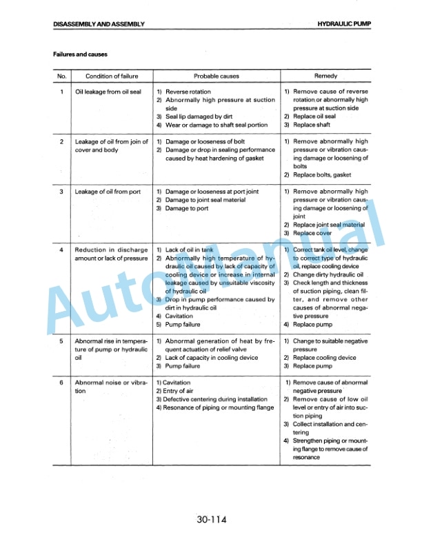
- 9.3. Hydraulic Pump
- 10. Conversion Tables
- 10.1. Millimeters to Inches
- 10.2. Inches to Millimeters
- 10.3. Cubic Meters to Cubic Yards
- 10.4. Cubic Yards to Cubic Meters
- 10.5. Liter to U.S. Gallon
- 10.6. Gallon to Liter
- 10.7. Liter to U.K. Gallon
- 10.8. Gallon to Liter
- 10.9. Kilogram to Pound
- 10.10. Pound to Kilogram
- 10.11. Kg/cm (squared) / lb.in. (squared)
- 10.12. kgm to ft.lb
- 10.13. Temperature
Rate this product
You may also like
Komatsu Shop Manual PDF
$40.00

