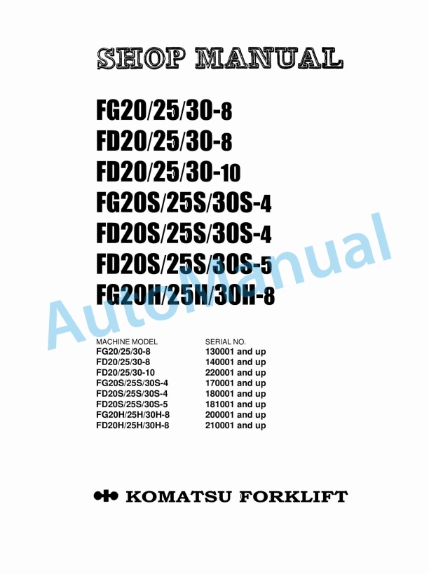
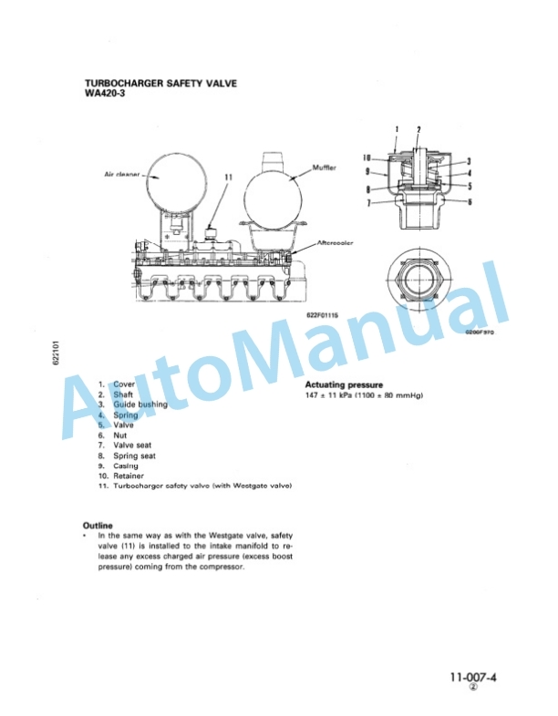
Komatsu FG20-8, FG25-8, FG30-8, FD20-8, FD25-8, FD30-8, FD20-10, FD25-10, FD30-10, FG20S-4, FG25S-4, FG30S-4, FD20S Shop Manual
$40.00
- Type Of Manual: Shop Manual
- Format: PDF
- Size: 26.5MB
- Number of Pages: 539
Category: Komatsu Shop Manual PDF
-
Model List:
- FG20-8 Forklift Truck
- FG25-8 Forklift Truck
- FG30-8 Forklift Truck
- FD20-8 Forklift Truck
- FD25-8 Forklift Truck
- FD30-8 Forklift Truck
- FD20-10 Forklift Truck
- FD25-10 Forklift Truck
- FD30-10 Forklift Truck
- FG20S-4 Forklift Truck
- FG25S-4 Forklift Truck
- FG30S-4 Forklift Truck
- FD20S-4 Forklift Truck
- FD25S-4 Forklift Truck
- FD30S-4 Forklift Truck
- FD20S-5 Forklift Truck
- FD25S-5 Forklift Truck
- FD30S-5 Forklift Truck
- FG20H-8 Forklift Truck
- FG25H-8 Forklift Truck
- FG30H-8 Forklift Truck
- 1. ASFORE
- 1.1. FOREWORD
- 1.2. DISASSEMBLY AND ASSEMBLY DIAGRAM
- 1.3. DESCRIPTION OF THE SYMBOLS
- 2. ASGEN
- 2.1. GENERAL AND SPECIFICATIONS
- 2.1.1. General locations
- 2.1.2. Machine serial number
- 2.1.3. Engine serial number
- 2.1.4. Weight of main components
- 2.1.5. Specifications
- 2.1.6. Overall dimensions
- 2.1.7. Standard tightening torque
- 2.1.8. Periodic replacement
- 2.1.9. Precautions for maintenance
- 3. AGDIS
- 3.1. DISASSEMBLY AND ASSEMBLY
- 3.1.1. SERIES
- 3.1.1.1. General disassembly
- 3.1.1.2. General assembly
- 3.1.1.3. Tighteneing torque
- 3.1.2. SERIES
- 3.1.2.1. General disassembly
- 3.1.2.2. General assembly
- 3.1.2.3. Tightenening torque
- 3.2. MAINTENANCE STANDARD
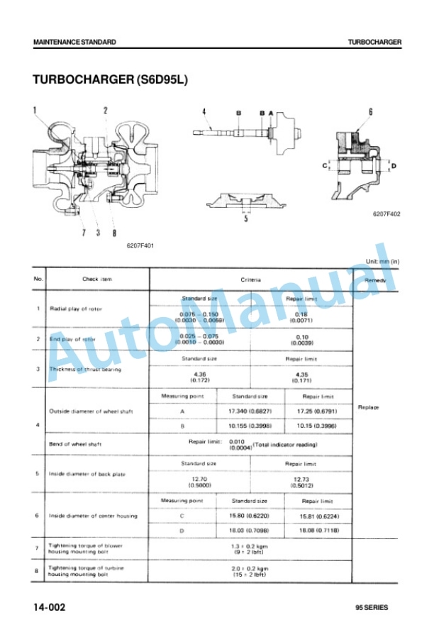
- 3.3. Turbocharger
- 3.4. Cylinder head
- 3.5. Valve and valve guide
- 3.6. Rocker arm shaft, push rod and tappet
- 3.7. Cylinder block
- 3.8. Crankshaft
- 3.9. Camshaft
- 3.10. Timing gear
- 3.11. Piston, piston ring and piston pin
- 3.12. Connecting rod
- 3.13. Flywheel and flywheel housing
- 3.14. Oil pump
- 3.15. Regulator valve
- 3.16. Water pump and thermostst
- 4. AGSERV
- 4.1. SERVICE INFORMATION
- 4.2. Procedure for selection and installation of pistons on 4D95S (L) and 6D95L engine
- 5. AGSTRUC
- 5.1. STRUCTURE AND FUNCTION
- 5.2. GENERAL STRUCTURE
- 5.3. INTAKE AND EXHAUST SYSTEM
- 5.3.1. Intake and exhaust system
- 5.3.2. Main circulation system
- 5.3.3. Timing gear
- 5.3.4. Valve system
- 5.3.5. Flywheel and flywheel housing
- 5.4. LUBRICATION SYSTEM
- 5.4.1. Lubrication system chart
- 5.4.2. Oil pump
- 5.4.3. Oil filter
- 5.5. FUEL SYSTEM
- 5.5.1. Fuel system chart
- 5.5.2. Fuel injection pump
- 5.5.3. Fuel injection nozzle
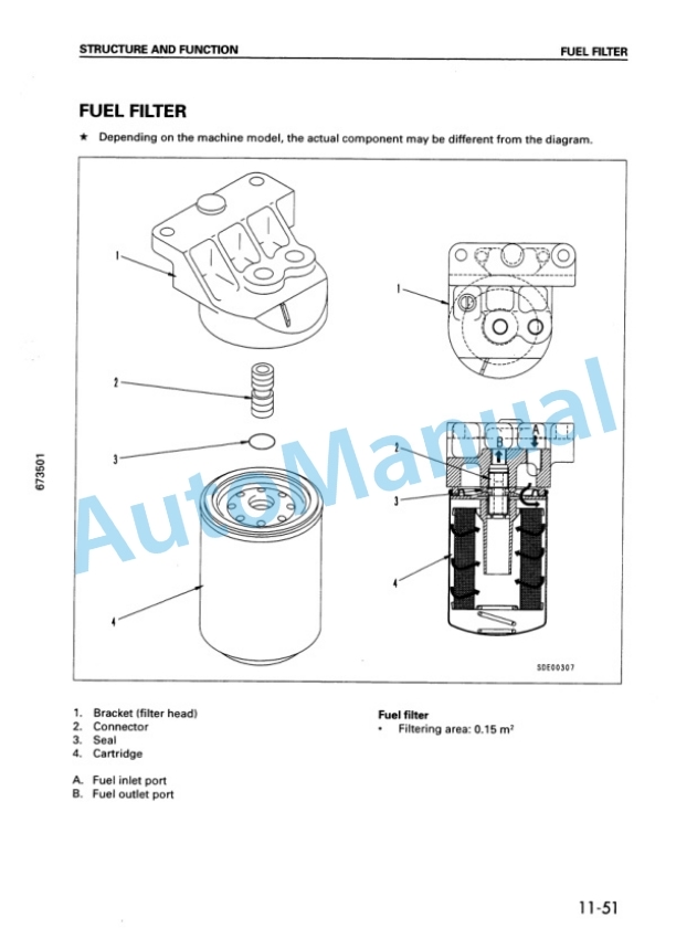
- 5.5.4. Fuel filter
- 5.6. COOLING SYSTEM
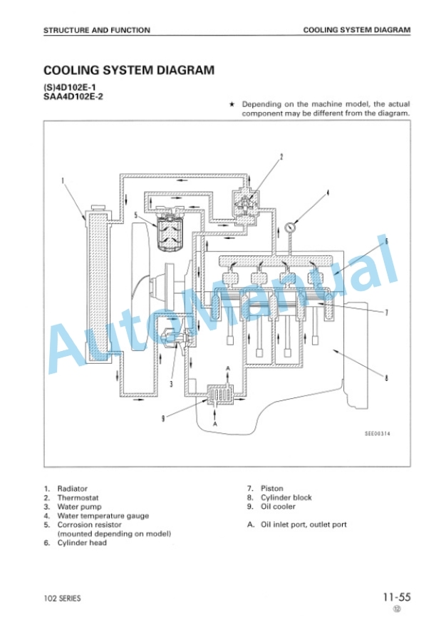
- 5.6.1. Cooling system chart
- 5.6.2. Water pump
- 5.6.3. Oil cooler (option)
- 5.6.4. Thermostat and fan drive
- 5.7. ELECTRICAL SYSTEM
- 5.7.1. Starting and charging circuit
- 5.7.2. Alternator
- 5.7.3. Starting motor
- 5.7.4. Electrical intake air heater
- 5.7.5. Fuel solenoid
- 6. AGTEST
- 6.1. TESTING AND ADJUSTING
- 6.2. INTAKE AND EXHAUST SYSTEM
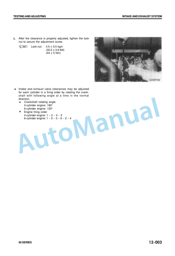
- 6.2.1. Adjusting valve clearance
- 6.2.2. Measuring exhaust gas color
- 6.3. ENGINE BODY
- 6.3.1. Measuring compression pressure
- 6.3.2. Measuring blowby pressure
- 6.4. FUEL SYSTEM
- 6.4.1. Checking and adjusting fuel injection timing
- 6.4.2. Adjustment of fuel injection pressure
- 6.4.3. Adjustment of fuel injection volume
- 6.4.4. Adjustment of governor
- 6.5. LUBRICATION SYSTEM
- 6.5.1. Measuring oil pressure
- 6.5.2. Measuring oil temperature
- 6.6. COOLING SYSTEM
- 6.6.1. Measuring water temperature
- 6.6.2. Testing and adjusting fan belt tension
- 6.7. PERFORMANCE TEST
- 6.7.1. Runin standard
- 6.7.2. Performance test criteria
- 6.7.3. Testing and adjusting tool list
- 6.7.4. Testing and adjusting data
- 6.8. TROUBLESHOOTING
- 6.8.1. Method of reading troubleshooting table
- 6.8.2. Troubleshooting table
- 7. ASAPPEN
- 7.1. APPENDIX
- 7.1.1. Change in structure of radiator mount
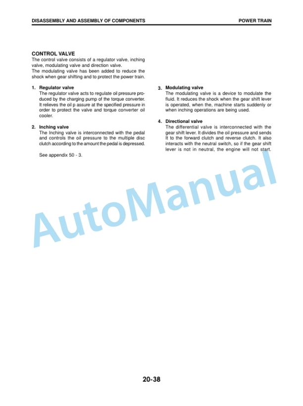
- 7.1.2. Change of TORQFLOW transmission control valve
- 7.1.3. Improved tilt valve
- 7.1.4. Quick on start system
- 7.1.5. Auto stop system
- 7.1.6. Local modification for full transisterized ignition system
- 8. ASDIS
- 8.1. DISASSEMBLY AND ASSEMBLY OF COMPONENTS
- 8.1.1. POWER TRAIN
- 8.1.1.1. General
- 8.1.1.2. Clutch
- 8.1.1.3. Transmission
- 8.1.1.4. Torque converter
- 8.1.1.5. TORQFLOW transmission
- 8.1.1.6. Front axle
- 8.1.1.7. Differential
- 8.1.1.8. Front wheel, Rear wheel
- 8.1.2. STEERING SYSTEM
- 8.1.2.1. General
- 8.1.2.2. Power steering pump
- 8.1.2.3. Steering gear box
- 8.1.2.4. Power steering cylinder
- 8.1.2.5. Rear axle
- 8.1.3. BRAKE SYSTEM
- 8.1.3.1. General
- 8.1.3.2. Master cylinder
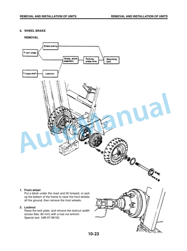
- 8.1.3.3. Wheel brake
- 8.1.4. HYDRAULIC SYSTEM
- 8.1.5. MAST AND RELATED PARTS
- 8.2. REMOVAL AND INSTALLATION OF UNIT
- 8.2.1. STRUCTURE
- 8.2.2. FLOW CHART
- 8.2.3. REMOVAL AND INSTALLATION OF UNIT
- 8.2.3.1. Mast
- 8.2.3.2. Lift cylinder
- 8.2.3.3. Torque converter (or clutch) Transmission Front axle
- 8.2.3.4. Engine
- 8.2.3.5. Muffler
- 8.2.3.6. Wheel brake
- 8.2.3.7. Rear axle
- 8.2.3.8. Power steering cylinder
- 8.2.3.9. Tightening torque
- 9. ASTEST
- 9.1. TESTING AND ADJUSTING
- 9.1.1. Engine
- 9.1.2. Drive system
- 9.1.3. Travel system
- 9.1.4. Steering system
- 9.1.5. Brake system
- 9.1.6. Work system
- 9.1.7. Hydraulic system
- 10. ASTROUB
- 10.1. TROUBLESHOOTING
- 10.1.1. Engine
- 10.1.2. Electrical system
- 10.1.3. Clutch and clutch transmission
- 10.1.4. TORQFLOW system
- 10.1.5. Steering system
- 10.1.6. Brake system
- 10.1.7. Hydraulic system
- 11. AWELEC
- 11.1. ENGINE ELECTRICAL SYSTEM
- 11.2. ENGINE LUBRICATION SYSTEM
- 11.3. OIL PUMP
- 12. AWMECH
- 12.1. ENGINE MECHANICAL
- 12.1.1. DISASSEMBLY
- 12.1.2. INSPECTION AND CORRECTION
- 12.1.3. ASSEMBLY
- 12.1.4. TIGHTENING TORQUE
Rate this product
You may also like
Komatsu Shop Manual PDF
$40.00

