


Komatsu Operation and Maintenance Manual PDF
Komatsu 330M Dump Truck Operation and Maintenance Manual DG713

Komatsu Operation and Maintenance Manual PDF
Komatsu 210M Dump Truck Operation and Maintenance Manual DG714
Komatsu Operation and Maintenance Manual PDF
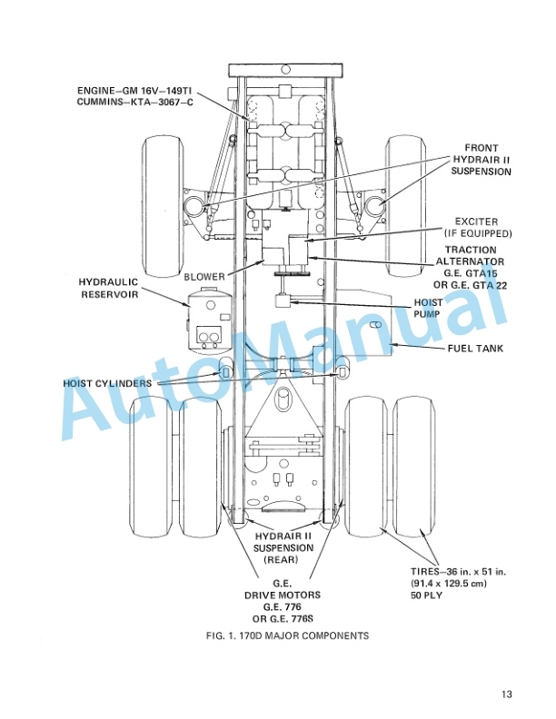
Komatsu 170D Dump Truck Operation and Maintenance Manual DG534
Komatsu Operation and Maintenance Manual PDF
Komatsu 530M Dump Truck Operation and Maintenance Manual DG716
Komatsu Operation and Maintenance Manual PDF
Komatsu 630E Dump Truck Operation and Maintenance Manual DG738
Komatsu Operation and Maintenance Manual PDF
Komatsu 210M Dump Truck Operation and Maintenance Manual DG692
Komatsu Operation and Maintenance Manual PDF
Komatsu 450FXL-1 Crawler Feller Buncher Operation and Maintenance Manual CEAM023802

Komatsu Operation and Maintenance Manual PDF
Komatsu 210M Dump Truck Operation and Maintenance Manual DG615
Komatsu Operation and Maintenance Manual PDF
Komatsu 730E Dump Truck Operation and Maintenance Manual CEAM020001
Komatsu Operation and Maintenance Manual PDF
Komatsu 730E Dump Truck Operation and Maintenance Manual CEAM011001